Chapter 12 Typical Atrial Flutter
Pathophysiology
Right Atrial Anatomy
The posterior smooth-walled RA and the anterolateral trabeculated RA are separated by the crista terminalis on the lateral wall and the eustachian ridge in the inferior aspect. The sulcus terminalis, where the sinus node is located, is a subtle groove on the epicardial surface of the heart corresponding to the crista terminalis. The crista terminalis is a C-shaped, convex, thick muscular ridge that runs from the high septum, anterior to the orifice of the SVC superiorly, and courses caudally along the posterolateral aspect of the RA. In its inferior extent, it courses anteriorly to the orifice of the IVC. As the crista reaches the region of the IVC, it is extended by the eustachian valve ridge. The eustachian valve is the remnant of the embryonic sinus venosus valve, which manifests as a flap of variable thickness and mobility along the orifice of the IVC; this valve can continue as a ridge superiorly along the floor of the RA to the ostium of the CS (CS os), to join the valve of the CS, form the tendon of Todaro, and then continue onto the interatrial septum as the inferior limbus of the fossa ovalis.1
The tricuspid annulus lies anterior to the body of the RA, and its inferior portion lies a short distance (approximately 1 to 4 cm) anterior to the eustachian ridge, although its course varies among individuals.2 The cavotricuspid isthmus (CTI) is the part of the RA between the ostium of the IVC and the eustachian ridge (posteriorly) and the tricuspid annulus (anteriorly). The CTI runs in an anterolateral-to-posteromedial direction, from the low anterior RA to the low septal RA (see Fig. 17-1). Its width and muscle thickness are variable, from a few millimeters to more than 3 cm in width and more than 1 cm in depth. The CTI becomes wider in a medial-to-lateral direction, and it is thinnest in its central portion. A thick eustachian ridge (greater than 4 mm) is seen in 24% of patients. At mid-diastole, the central isthmus is straight in 8% of patients, concave in 47% of patients, and pouch-like (more than 5 mm) in 45% of patients.3,4 The eustachian ridge (often composed of partly or largely fibrous tissue) occurs as an elevation on the CTI. The area between the tricuspid annulus and the eustachian ridge is referred to as the subeustachian isthmus, whereas the downslope of the eustachian ridge leads to the junction of the RA and IVC. The pectinates, as they fan out from the crista terminalis or other muscle bundles on the CTI, typically spare the myocardium just atrial to the tricuspid valve. This smooth portion of the cavotricuspid annulus is referred to as the vestibular portion.1 In the normal heart, CTI anatomy can be flat, “hilly” (from prominent eustachian ridge or pectinate muscles, or both), concave, or have a pouch-like recess.
Typical Atrial Flutter Circuit
Typical atrial flutter (AFL) is a type of macroreentrant atrial tachycardia (AT) that uses the CTI as an essential part of its circuit. The circuit boundaries are the tricuspid annulus, crista terminalis, IVC orifice, eustachian ridge, CS os, and probably fossa ovalis. These barriers (lines of conduction block) can be functional or anatomical and are necessary to provide adequate path length for the flutter reentry circuit. Whereas the anterior boundary of the tachycardia circuit has been well established as being the tricuspid ring, the posterior boundaries are more complex and not as well defined, and they occur at a variable distance from the anterior border; the posterior borders are narrowest in the region of the eustachian ridge and widest in the anterior part of the RA.2,5–8
The CTI provides the protected zone of slow conduction necessary for the flutter reentry circuit. The area of slowest conduction is probably localized in the lateral aspect of the CTI in younger patients and in the medial aspect in older patients.9 Conduction velocity in the CTI during pacing in sinus rhythm is slower in patients with typical AFL compared with those without any history of AFL.3,10 The mechanism of the slower conduction velocity in the CTI, relative to the interatrial septum and RA free wall, is uncertain but can be related to the anisotropic fiber orientation. With aging or atrial dilation, intercellular fibrosis can change the density of gap junctions and produce nonuniform anisotropic conduction through the trabeculations of the CTI. Additionally, the CTI and RA in patients with typical AFL are significantly larger than those in a control population.6
The crista terminalis plays an important role as a functional barrier during typical AFL. Conduction delay and rate-related transverse block across the crista terminalis has been consistently observed in sinus rhythm and during pacing in humans. A line of transverse conduction block along the crista terminalis serving as a lateral boundary can be determined by the presence of double and split potentials recorded during AFL or rapid pacing from either side of the crista terminalis during electrophysiological (EP) testing. Structural characteristics of the crista terminalis influence transverse conduction; steep slope and arborization of the crista terminalis have been implicated as geometric factors in its transverse conduction block. Typical AFL is more likely to occur in the setting of a thicker and continuous crista terminalis, and these patients are more likely to exhibit transverse crista terminalis conduction block at longer cycle lengths (CLs) as opposed to controls. Similarly, the region posterior to the crista terminalis (the posterior smooth-walled RA) also has been shown to demonstrate functional transverse conduction block during AFL or rapid pacing.11,12
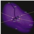
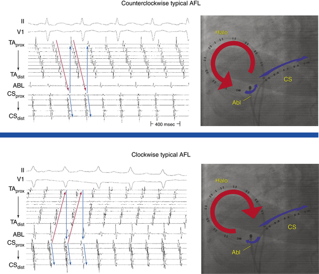
Typical AFL is of two types: counterclockwise and clockwise.5 In counterclockwise AFL, the activation wavefront propagates caudocephalically up the septal side of the tricuspid annulus toward the crista terminalis and advances cephalocaudally along the lateral wall of the RA to reach the lateral tricuspid annulus, after which it propagates through the CTI (“counterclockwise” as viewed in the left anterior oblique [LAO] view from the ventricular side of the tricuspid annulus). The width of the activation wavefront in typical AFL varies considerably, determined by the distance between the anterior and posterior boundaries at any given part of the circuit. It is very narrow inferiorly at the CTI and substantially wider moving upward. The substantial distance between anterior and posterior borders as well as the anatomical barriers superiorly, combined with variability in the completeness of the posterior border, creates conditions for substantial variability in the upper part of the circuit. Despite a relatively similar activation sequence, the active circuit (as determined by entrainment mapping) is variable. Most commonly, the reentrant wavefront courses not around the tricuspid annulus but obliquely between anterior and posterior borders away from the tricuspid annulus along any available, more rapidly conducting segments. Consequently, significant portions of the RA, including areas around the tricuspid annulus, can often be passively activated. In many subjects, the upper portions of the circuit pass behind the RA appendage and lie near or at the posterior circuit border, or they bifurcate around the SVC or RA appendage, or both. The posterior border can extend completely or partially between the IVC and the SVC.7,8
The flutter circuit is entirely confined within the RA. Left atrial (LA) activation occurs as a bystander and follows transseptal conduction across the inferior CS-LA connection, Bachmann bundle, or fossa ovalis.2,6
In clockwise (reverse typical) AFL, activation propagates in the direction opposite to that in counterclockwise typical AFL (Fig. 12-1). Clockwise AFL is observed in only 10% of clinical cases, despite the fact that it is easily inducible in the EP laboratory with programmed electrical stimulation. Clockwise AFL can be induced in the EP laboratory in approximately 50% of patients who clinically present with only counterclockwise AFL. The 9:1 clinical predominance of counterclockwise AFL can be related to the localization of an area with a low safety factor for conduction in the CTI, close to the atrial septum. Additionally, counterclockwise AFL is more likely to be induced with rapid atrial pacing from the CS os. Conversely, clockwise AFL is more likely to be induced with pacing from the low lateral RA pacing. These observations may be related to the anisotropic properties of the CTI and the development of rate-dependent conduction delays and unidirectional block necessary for tachycardia induction, which may be affected by the site of stimulation.2,6 Spontaneous AFL initiation may be related to rapid bursts of pulmonary vein discharges (atrial fibrillation [AF]).
Double-Wave Reentry
Double-wave reentry is manifest by acceleration of the tachycardia rate but with identical surface and intracardiac electrogram morphology. It can be recognized by the simultaneous activation of the superior and inferior regions of the tricuspid annulus, with all activation being sequential. This rhythm rarely lasts for more than a few beats and can serve as a trigger for AF. Because the CTI is still a necessary part of the circuit, double-wave reentry is amenable to CTI ablation.2,6
Clinical Considerations
Epidemiology
It is estimated that the overall incidence of AFL in the United States is 88 per 100,000 person-years. AFL accounts for approximately 15% of supraventricular arrhythmias and frequently coexists with or precedes AF. Although in clinical practice AFL appears to be less common than paroxysmal supraventricular tachycardia, population-based data show that in the general population, AFL is diagnosed for the first time more than twice as often. Adjusted for age, the incidence of AFL in men is more than 2.5 times that of women. Paroxysmal AFL can occur in patients with no apparent structural heart disease, whereas chronic AFL is usually associated with underlying heart disease, such as valvular or ischemic heart disease or cardiomyopathy. At highest risk of developing AFL are men, older adults, and individuals with preexisting heart failure or chronic obstructive lung disease. In approximately 60% of patients, AFL occurs as part of an acute disease process, such as exacerbation of pulmonary disease, following cardiac or pulmonary surgery, or during acute myocardial infarction.13
Principles of Management
Acute Management
Acute therapy for patients with AFL depends on the clinical presentation and may include cardioversion and the use of AVN blockers to slow the ventricular rate during the AFL. Cardioversion (electrical or chemical) is commonly the initial treatment of choice. Electrical cardioversion is almost always successful in terminating AFL, and it often requires relatively low energies (less than 50 J). Chemical cardioversion can be achieved with intravenous ibutilide in 38% to 76% of cases, and this agent is more effective than intravenous amiodarone, sotalol, and class IC agents. Overdrive atrial pacing (via a catheter in the esophagus or the RA) can effectively terminate typical AFL, but it can also induce conversion of AFL into AF. Anticoagulation in the pericardioversion period should be considered and is guided by the duration of the AFL and the patient’s stroke risk factors, by using the same criteria as for AF (see Chap. 15).14
Chronic Management
When AFL occurs as part of an acute disease process, long-term therapy of the arrhythmia is usually not required after sinus rhythm is restored and the underlying disease process is treated. The long-term success rate of antiarrhythmic drugs to prevent AFL recurrence appears to be limited, and complete suppression of AFL can be difficult to achieve. On the other hand, ablation is highly successful at the conclusion of a relatively short and low-risk procedure. Therefore, catheter ablation of the CTI is the treatment of choice for typical AFL, whether paroxysmal or persistent, and long-term drug therapy is rarely indicated and should be reserved for unusual circumstances.2
Several antiarrhythmic drugs have demonstrated efficacy in suppression of AFL, including class IA (quinidine, procainamide, and disopyramide), class IC (flecainide and propafenone), and class III (sotalol, amiodarone, dofetilide, and dronedarone) agents. In the absence of structural heart disease, class IC agents are the drugs of choice. The use of antiarrhythmic agents should be instituted in conjunction with AVN blockers to avoid the risk of rapid ventricular rates secondary to the vagolytic effects of class I drugs and slowing of the flutter rate.14
Electrocardiographic Features
P Waves
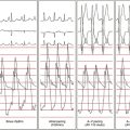
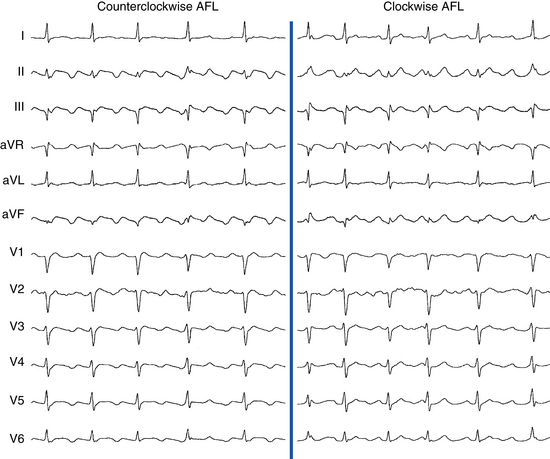
Flutter waves appear as atrial complexes of constant morphology, polarity, and CL. Typically, flutter waves are most prominent in the inferior leads (II, III, aVF) and lead V1. In the inferior leads, they resemble a picket fence (sawtooth) because the leads are primarily negative. This consists of a downsloping segment, followed by a sharper negative deflection, and then a sharp positive deflection, with a positive overshoot leading to the next downsloping plateau. The relative size of each component can vary markedly.2
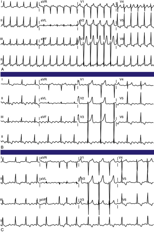
Counterclockwise AFL (Fig. 12-2) can be characterized by pure negative deflections in the inferior leads, negative and then positive deflections that are equal in size, or a small negative and then a larger positive deflection. Those three varieties coexist with tall positive, small positive, or biphasic P waves in lead V1, respectively. With progression across the precordium, the initial component rapidly becomes inverted and the second component isoelectric usually by lead V2 to V3. This produces the overall impression of an upright flutter wave in lead V1, which becomes inverted by lead V6. A negative deflection always precedes the positive deflection in the inferior leads in counterclockwise AFL, and the degree of positivity in the inferior leads appears to be related to the coexistence of heart disease and LA enlargement. Lead I is low-amplitude isoelectric, and lead aVL is usually upright.15
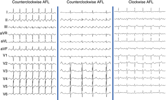
The surface ECG appearance of clockwise typical AFL is more variable than that of counterclockwise typical AFL, but in many respects, clockwise AFL presents an inversion of the appearance in counterclockwise AFL. Clockwise AFL generally has broad positive deflections in the inferior leads, with characteristic notching (see Fig. 12-2).2 However, there is an inverted component preceding the upright notched component. Depending on the amplitude of this component, the appearance can be of continuous undulation without an obviously predominant upright or inverted component. On other occasions, it may appear that the inverted component is dominant, thus superficially mimicking counterclockwise AFL. Lead V1 is characterized by a wide negative and usually notched deflection. There is transition across the precordium to an upright deflection in lead V6. Lead I is usually upright, and lead aVL is low-amplitude negative and notched.15
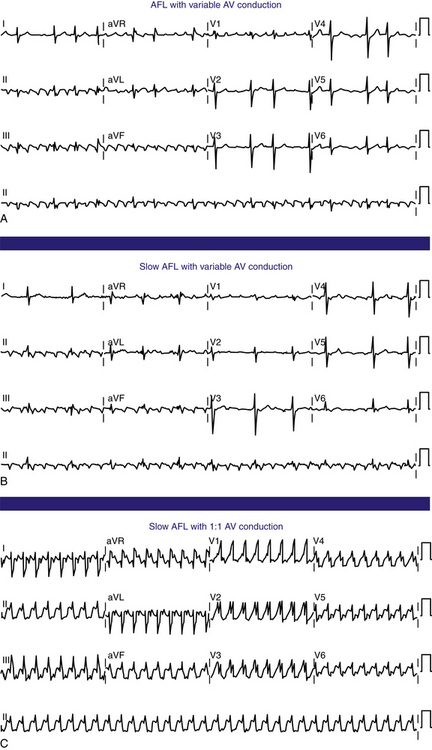
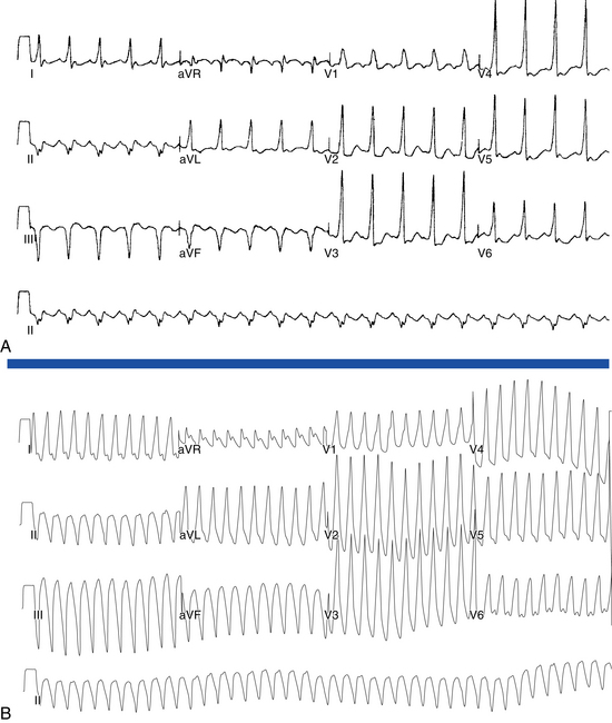
Typical AFL usually has an atrial rate of 240 to 340 beats/min. However, AFL can be slower in patients receiving antiarrhythmic agents or after incomplete CTI ablation (Fig. 12-3), whereby flutter CLs as long as 450 milliseconds have been observed. If the ventricular response is half the atrial rate, it can be difficult to identify flutter waves “buried” within the QRS or T waves (Fig. 12-4). Close inspection of the QRS and T waves, and comparisons with ECGs obtained in normal sinus rhythm, can help identify buried flutter waves. Furthermore, vagal maneuvers and AVN blockers can slow AV conduction and unmask the flutter waves.
Atrioventricular Conduction
Most commonly, 2:1 AV conduction is present during AFL. Variable AV conduction and larger multiples (e.g., 4:1 or 6:1) are not uncommon. Slowing the atrial rate during AFL caused by antiarrhythmic drugs or following a prior incomplete CTI ablation can result in a paradoxical increase in the ventricular rate caused by better AVN conduction of the slower flutter beats (Fig. 12-5). Rapid 1:1 AV conduction is most commonly seen in patients with anterogradely conducting bypass tracts (Fig. 12-6), but it may also be present in cases of enhanced AVN conduction secondary to high sympathetic tone (e.g., exercise, sympathomimetic drugs).2
QRS Morphology
The QRS complex during AFL is often identical to that during sinus rhythm. However, flutter beats can be aberrantly conducted because of functional bundle branch block, most frequently right bundle branch block (see Fig. 12-5). Even with normal ventricular conduction, the QRS complex may be slightly distorted by temporal superimposition of flutter waves on the QRS complex. Thus, the QRS complex can appear to acquire a new or larger R, S, or Q wave.2
Electrophysiological Testing
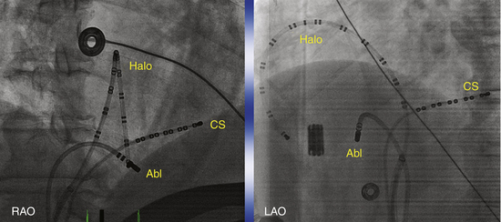
Typically, a decapolar catheter (positioned into the CS with the proximal electrodes bracketing the CS os) and a multipolar (20 or 24 pole) Halo catheter (positioned at the tricuspid annulus) are used to map typical AFL. The distal tip of the Halo catheter is positioned at 6 to 7 o’clock in the LAO view, so that the distal electrodes will record the middle and lateral aspects of the CTI, the middle electrodes will record the anterolateral RA, and the proximal electrodes may record the RA septum (depending on the catheter used and RA size). Instead of the Halo and CS catheters, some laboratories use a single duodecapolar catheter around the tricuspid annulus, thus extending the catheter tip inside the CS. Such a catheter can straddle the CTI and provide recording and pacing from the medial and lateral aspects of the isthmus, assuming good catheter-tissue contact at these locations. In the latter arrangement, however, the body of the duodecapolar catheter crossing over the CTI can potentially hinder manipulation and positioning of the ablation catheter tip to achieve adequate tissue contact for effective ablation.
Induction of Tachycardia
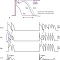
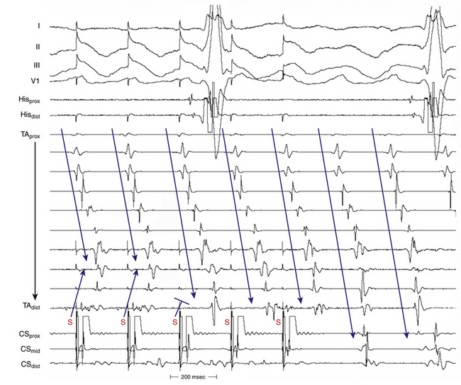
AFL can be induced readily with programmed electrical stimulation in most patients with a clinical history of AFL. Reproducible initiation of counterclockwise AFL is possible in more than 95% of patients.16 Rapid atrial pacing is more likely to induce AFL than a single AES, but as likely as introducing two AESs. On the other hand, the frequency of single or double AESs initiating AFL is low in patients without a history of AFL (less than 10%). Counterclockwise AFL is more likely to be induced by stimulation from the CS os; conversely, clockwise AFL is more likely to be induced with low lateral RA pacing. Induction of AFL usually occurs once unidirectional CTI block develops during pacing (Fig. 12-7). The faster the pacing rate and the shorter the AES coupling intervals, the more likely it will be that AF is induced, which is usually self-terminating but can be sustained in less than 10% of patients with no clinical history of AF. The significance of induction of AF in these patients is uncertain.
Tachycardia Features
The presence of anterogradely conducting bypass tracts with a short refractory period can result in preexcited AFL with rapid 1:1 AV conduction. Infusion of isoproterenol can enhance AVN function and occasionally facilitate 1:1 AV conduction, especially when the atrial rate is relatively slow.2 Adenosine increases the degree of AV block, but it also shortens atrial refractoriness and can result in the degeneration of AFL into AF.
Diagnostic Maneuvers during Tachycardia
Atrial Extrastimulation During Atrial Flutter
An AES commonly results in resetting of the AFL circuit.16 The closer the site of atrial stimulation is, the easier the resetting of the AFL circuit at longer coupling intervals will be. AFL has a resetting response pattern typical of reentrant circuits with fully excitable gaps: flat (for approximately 15% to 30% of the tachycardia CL, equal to approximately 30 to 63 milliseconds in the absence of drugs, and up to 100 milliseconds with class I antiarrhythmic agents) and then an increasing return CL with progressively shorter coupling intervals. The ability to capture the atrium without affecting (resetting) the AFL circuit timing indicates that the pacing site is outside the AFL circuit (e.g., RA appendage or distal CS).
It is usually difficult for a single AES to terminate AFL because AFL has a sizable fully excitable gap (15% to 30% of the tachycardia CL) that makes it difficult for a single AES to penetrate the AFL circuit with adequate prematurity to terminate the AFL without intervening atrial refractoriness and intraatrial conduction delays. An AES delivered in the region of the CTI has the greatest chance of terminating AFL because it can capture the isthmus tissue with a very short coupling interval (close to the ERP of this critical site), given the lack of intervening tissue between the stimulation site and isthmus. Termination of AFL always occurs because of conduction block in the CTI.
Atrial Pacing During Atrial Flutter
Entrainment
Overdrive atrial pacing at long CLs (i.e., 10 to 30 milliseconds shorter than the tachycardia CL) can almost always entrain typical AFL. The slower the pacing rate and the farther the pacing site from the reentrant circuit, the longer the pacing drive will need to be to penetrate and entrain the tachycardia. As discussed in detail in Chapter 13, achievement of entrainment of the AT establishes a reentrant mechanism of the tachycardia and excludes triggered activity and abnormal automaticity as potential mechanisms. However, it is important to understand that the mere acceleration of the tachycardia to the pacing rate and then resumption of the original tachycardia after cessation of pacing do not establish the presence of entrainment. After cessation of each pacing drive, the presence of entrainment should be verified by demonstrating the presence of fixed fusion of the paced complexes at a given pacing CL, progressive fusion at faster pacing CLs, and resumption of the same tachycardia morphology following cessation of pacing with a nonfused complex at a return cycle equal to the pacing CL. During entrainment of AFL, fusion of the stimulated impulse can be observed on the surface ECG, but it is easier to recognize on intracardiac recordings from the Halo and CS catheters. Entrainment with manifest fusion can be demonstrated with pacing from sites outside the CTI, such as lateral RA and CS. Conversely, pacing at the CTI results in entrainment with concealed fusion, whereby P waves (on the surface ECG and intracardiac recordings) during pacing are identical to those during the tachycardia.17,18
Termination
More rapid atrial burst pacing (pacing CL 20 to 50 milliseconds shorter than the AFL CL) results in termination of AFL in most cases.16 Termination of AFL during rapid pacing can be indicated by a sudden change of P wave morphology on the surface ECG and by a change of atrial activation sequence in the HB and CS os recordings. This is seen particularly with high RA pacing during counterclockwise AFL, whereby on termination of AFL, the negative flutter waves in the inferior leads change suddenly into upright P waves, thus reflecting a change in the atrial activation sequence to one of high RA pacing (i.e., simultaneous RA lateral and septal activation in a craniocaudal direction).5 However, if the pacing site is distant from the AFL circuit (e.g., distal CS), a large mass of the atrial tissue can be captured by the pacing stimulus, to produce a marked change in P wave morphology (i.e., manifest fusion) without terminating the AFL. Failure to terminate AFL with rapid pacing can be caused by any of the following: (1) a short period of pacing or pacing at a relatively long CL—the closer the pacing CL is to the tachycardia CL, the longer the pacing duration will need to be to terminate the tachycardia; (2) a pacing site distant from the AFL circuit, with the intervening atrial tissue preventing penetration of the AFL circuit; or (3) the possibility that an apparent AFL on the ECG may actually be AF with streaming of the RA activation wavefront or may be a focal nonreentrant AT.5,16
Acceleration
Acceleration by overdrive pacing refers to sustained shortening of the tachycardia CL following cessation of pacing. Atrial pacing rarely can accelerate AFL into one of two different tachycardias: double-wave reentry or lower loop reentry.16 Double-wave reentry is manifest by acceleration of the tachycardia rate but with identical surface and intracardiac electrogram morphology, and it can be recognized by having simultaneous activation of the superior and inferior regions of the tricuspid annulus, with all activation being sequential. This rhythm rarely lasts for more than a few beats and may serve as a trigger for AF. Lower loop reentry is a form of CTI-dependent AFL with a reentrant circuit around the IVC. This arrhythmia is usually transient and terminates by itself or converts spontaneously into AFL or AF (see Chap. 13).19–21
Mapping
Activation Mapping
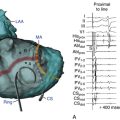
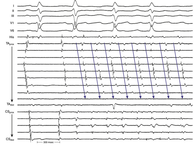
The simultaneous recording from endocardial sites around the tricuspid annulus (which encompasses most of the flutter macroreentrant circuit) by the Halo and CS catheters significantly facilitates activation mapping during typical AFL, and sequential point-by-point activation mapping is usually not required. The RA activation sequence during counterclockwise AFL occurs sequentially down the lateral RA wall and adjacent to the crista terminalis, across the CTI (with some delay because of slow conduction across the CTI), past the CS os, up the atrial septum, over the roof of the RA, and back to the lateral free wall of the RA (in a proximal-to-distal direction along the Halo electrodes; see Fig. 12-1). This sequence is reversed during clockwise AFL (see Fig. 12-1).
During AFL, double potentials are seen on the crista terminalis and along the eustachian ridge and indicate lines of block (fixed or functional) along those structures. Activation of the CS propagates in a proximal-to-distal direction.12
Occasionally, P wave morphology on the surface ECG resembles typical AFL, but intracardiac recordings show that parts of the atria (commonly the LA) have disorganized atrial activity (Fig. 12-8). Such rhythms behave more like AF than AFL, but they may be converted to true typical AFL with antiarrhythmic drugs.16
Entrainment Mapping
Entrainment mapping provides information about sites of the RA or LA that are part of the reentrant circuit, those that are outside the circuit, and the critical isthmus in the macroreentrant circuit. Entrainment also qualitatively estimates how far the reentrant circuit is from the pacing site. However, before attempting to use entrainment methods for mapping, it is necessary first to demonstrate that the tachycardia can be entrained, thus providing strong evidence that it is caused by reentry rather than by triggered activity or automaticity. At sites of entrainment, there should be confirmation of consistent capture of the atrium at the pacing CL for several beats with minimal or no change in the surface morphology or intracardiac electrograms and continuation of the identical tachycardia after pacing. Evaluation of the PPI or other criteria is meaningless when the presence of true entrainment has not been established. Additionally, it is important to verify the absence of termination and reinitiation of the tachycardia during the same pacing drive.7
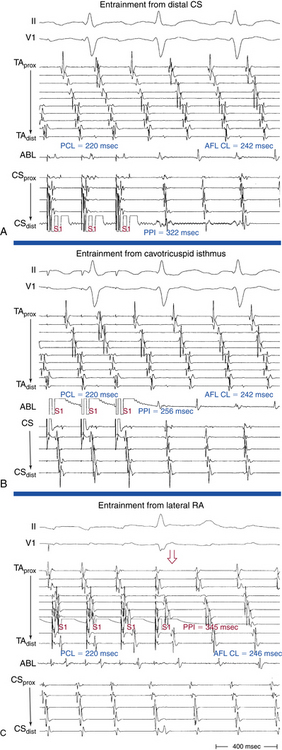
Once the presence of entrainment is verified, several criteria can be used to indicate the relation of the pacing site to the reentrant circuit. As discussed in detail in Chapter 13, the first entrainment criterion to be sought is concealed fusion. Entrainment with concealed fusion indicates that the pacing site is in a protected isthmus located within or attached to the reentrant circuit. Whether this protected isthmus is crucial to the reentrant circuit or just a bystander site needs to be verified by other criteria, mainly comparing the PPI with the tachycardia CL and the stimulus-exit interval with the electrogram-exit interval (Fig. 12-9). The diagnosis of CTI-dependent AFL is established when pacing from the CTI results in entrainment with concealed fusion and a PPI that is equal (within 20 milliseconds) to the flutter CL and an electrogram-exit interval that is equal (within 20 milliseconds) to the stimulus-exit interval. During counterclockwise AFL, a site medial to the CTI, such as the CS os, may be used to represent the exit of the reentrant wavefront. Conversely, in clockwise AFL, a site lateral to the tricuspid annulus, such as the distal Halo electrode, may be used (Table 12-1).17,18
• Manifest atrial fusion on surface ECG or intracardiac recordings (fixed fusion at a single pacing CL, or both, and progressive fusion on progressively shorter pacing CL)
• PPI − tachycardia CL < 20 msec
• The interval between the stimulus artifact to the onset of the flutter wave on the surface ECG is equal to the interval between the local electrogram on the pacing site to the onset of the flutter wave on the surface ECG.
• Concealed atrial fusion (i.e., paced atrial waveform on the surface ECG and intracardiac recordings is identical to the AFL waveform)
• PPI − tachycardia CL < 20 msec
• The interval between the stimulus artifact to the onset of the flutter wave on the surface ECG is equal to the interval between the local electrogram on the pacing site to the onset of the flutter wave on the surface ECG.
AFL = atrial flutter; CL = cycle length; CS = coronary sinus; CS os = coronary sinus ostium; PPI = post-pacing interval; RA = right atrium.
Electroanatomical Mapping
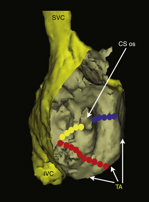
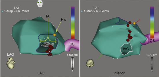
The mapping-ablation catheter is initially positioned, using fluoroscopy, at known anatomical points that serve as landmarks for the electroanatomical map. Anatomical and EP landmarks (IVC, SVC, CS, HB, and tricuspid annulus) are tagged. A set of six specific points (three at the tricuspid annulus and three at the mouth of the IVC) is acquired to delineate the individual isthmus anatomy. The catheter is then advanced slowly around the chamber walls to sample multiple points along the endocardium, thereby sequentially acquiring the location of its tip together with the local electrogram. Activation mapping is performed to define the atrial activation sequence. Reasonable numbers of points are homogeneously distributed in the RA, with careful mapping of endocardial sites around the tricuspid annulus and CTI. The local activation time at each site is determined from the intracardiac bipolar electrogram and is measured in relation to the fixed intracardiac electrogram obtained from the CS (reference) catheter. The activation map may also be used to catalog sites at which pacing maneuvers are performed during assessment of the tachycardia (e.g., sites with good pace maps). Activation maps display the local activation time by a color-coded overlay on the reconstructed 3-D geometry (see Videos 11 and 16).  The selected points of local activation time are color-coded.
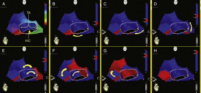
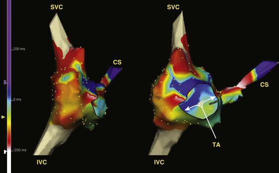
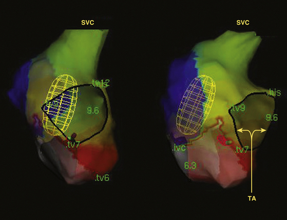
High-density 3-D electroanatomical maps during AFL can be useful in delineating the specific features of the AFL circuit and global RA activation during AFL. The activation map typically demonstrates a continuous progression of colors (from red to purple in the CARTO system and from white to purple in the NavX system) around the tricuspid annulus with close proximity of earliest and latest local activation and an activation time in a similar range to tachycardia CL, consistent with macroreentry (Figs. 12-10 and 12-11). The activation wavefront exits the CTI as a broad wavefront, spreading anterosuperiorly around the tricuspid annulus and posterosuperiorly. Lateral spread of the posterior wavefront is blocked along the vertical line in the posterolateral RA, a region marked by double potentials that coincides with the crista terminalis. The posterior wavefront propagates cranially around the SVC to merge with the activation wavefront circulating around the tricuspid annulus. The anterolateral wall of the RA is the last to activate as the wavefront reenters the lateral aspect of the CTI.
Noncontact Mapping
The EnSite 3000 noncontact mapping system (St. Jude Medical, St. Paul, Minn.) consists of a noncontact catheter with a multielectrode array surrounding a 7.5-mL balloon mounted at the distal end. The 9 Fr balloon catheter is advanced over a 0.035-inch guidewire under fluoroscopy guidance and is positioned in the middle and lower portion of the RA. The balloon is positioned in the center of the atrium and does not come in contact with the atrial walls being mapped. Intravenous heparin is administered before balloon deployment to keep the activated clotting time at 250 to 300 seconds. A conventional mapping-ablation catheter is used to collect geometry information. The mapping catheter is initially moved to known anatomical locations (IVC, SVC, CS, HB, and tricuspid annulus), which are tagged. Detailed geometry of the chamber is then reconstructed by moving the mapping catheter around the atrium.
After the chamber geometry is determined, mapping of the arrhythmia can begin. The data acquisition process is performed automatically by the system, and all data for the entire chamber are acquired simultaneously. The system then reconstructs unipolar electrograms simultaneously and superimposes them onto the virtual endocardium, to produce isopotential maps with a color range representing voltage amplitude (Fig. 12-12; see Video 9).  A default high-pass filter setting of 2 Hz is used to preserve components of slow conduction on the isopotential map. Color settings are adjusted so that the color range matches 1 to 1 with the millivolt range of the electrogram deflection of interest. Activation can be tracked on the isopotential map throughout the tachycardia cycle. Isochronal maps can also be created that represent progression of activation throughout the chamber relative to a user-defined electrical reference timing point (see Fig. 12-12).22
Although typical AFL is usually readily treated using standard ablation techniques, noncontact mapping can be used to confirm the anatomical location of the flutter circuit, reduce fluoroscopy time, and confirm CTI block after ablation. Noncontact mapping has also been used to identify and guide radiofrequency (RF) ablation of the site of residual conduction following incomplete linear ablation lesions at the isthmus. Because of its ability to record from multiple sites simultaneously, noncontact mapping can rapidly identify gaps in linear lesions. This is accomplished by analysis of one or more paced complexes originating adjacent to the line being assessed. This capability can be particularly helpful in patients who have recurrent AFL following a previous ablation. Because any number of maps can be superimposed on the initial geometry, bidirectional block at the ablation site can be rapidly identified during pacing following ablation. Tagging ablation areas during delivery of each RF impulse and a constantly visible ablation line offer another advantage—they ensure that no area is overlooked or ablated repeatedly.
Ablation
Target of Ablation
The CTI is the ideal target of AFL ablation because it is accessible, relatively narrow, short, safe to ablate, and essential for the AFL circuit (and not because it is the diseased area or the structure causing the AFL).23 The central part of the isthmus (the 6 o’clock region in a fluoroscopic LAO view) appears to be the optimal target site because it is the thinner part of the isthmus (19 ± 4 mm; range, 13 to 26 mm) and therefore is less likely to resist RF ablation. Other advantages of the central isthmus are the increased distance from the paraseptal isthmus, which contains, in 10% of cases, extensions of the AVN or AVN artery, and the increased distance from the inferolateral isthmus, where the right coronary artery is in close proximity to the endocardium (less than 4 mm).1,24
Alternatively, the tricuspid annulus–CS or IVC-CS isthmuses may be targeted (Fig. 12-13). However, for this approach to be successful, ablation within the CS is probably necessary. Such approaches are less successful in curing AFL.16 The paraseptal isthmus (tricuspid annulus–CS isthmus) has the thickest wall, compared with other parts of the inferior RA isthmus, although there is significant interindividual variability, and this structure is close to the arterial branch supplying the AVN and, in some cases, can contain the inferior extensions of the AVN. The inferolateral isthmus is the longest and is in closest proximity to the right coronary artery.24
Ablation Technique
Periprocedural anticoagulation for catheter ablation of persistent AFL is necessary to minimize thromboembolic stroke risk. LA stunning and increased spontaneous echo contrast within the LA can occur following cardioversion or ablation of these arrhythmias. A perception of increased bleeding risks of invasive procedures undertaken while a patient is receiving therapeutic warfarin doses led many operators to adopt a “bridging” strategy of conversion to enoxaparin, to allow ablation and subsequent hemostasis to be performed during a pause in anticoagulation (a strategy also recommended by the Heart Rhythm Society/European Heart Rhythm Association/European Cardiac Arrhythmia Society expert consensus statement).25 This strategy involves discontinuation of warfarin at least 3 to 5 days prior to ablation and starting heparin or enoxaparin after cessation of warfarin until the evening prior to the ablation procedure. Both enoxaparin and warfarin are then reinitiated within 4 to 6 hours after ablation and sheath removal, and enoxaparin is maintained until an optimal international normalized ratio (INR) level is achieved. However, an alternative strategy of uninterrupted periprocedure oral anticoagulation was found to be safer and more cost-effective for ablation of typical AFL. Bleeding complications were less frequent. Using this strategy, INR testing is required on the day of the procedure to confirm therapeutic anticoagulation, and transesophageal echocardiography is performed in patients with a subtherapeutic INR in the 3 weeks prior to the procedure. Another potential advantage of this strategy is the ability to reverse the effects of warfarin rapidly in the setting of a bleeding complication (e.g., pericardial bleeding) by using synthetic clotting factor concentrates or fresh frozen plasma infusion, whereas the effects of enoxaparin remain difficult to reverse; protamine has only a partial effect on its action.26
Catheter Positioning
A steerable ablation catheter with a distal ablation electrode of 4 or 8 mm is generally used.27 The catheter’s curve size and shape can affect the ability to position the catheter on the CTI, and the use of preshaped guiding sheaths (e.g., SR0, SL1, or ramp sheath; Daig, Minnetonka, Minn.) can help stabilize the catheter position and prevent the catheter from sliding off the CTI and in and out of the right ventricle (RV).
The CTI can be localized electroanatomically. The ablation catheter is advanced to the RV under fluoroscopy (right anterior oblique [RAO] view); the tip is deflected to achieve contact with the RV inferior wall and is withdrawn progressively until the electrogram shows small atrial and large ventricular electrograms. The distal tip of the ablation catheter is then adjusted under fluoroscopy on the CTI in the LAO view until it is midway between the atrial septum and RA lateral wall (pointing toward 6 o’clock in a 45-degree LAO view; Fig. 12-14;Video 18). 
Radiofrequency Ablation
After positioning of the ablation catheter on or near the tricuspid annulus, the catheter is gradually withdrawn either toward the IVC during continuous energy application (50 to 70 W, 60 to 120 seconds, targeting a temperature of 55°C to 60°C), or in a stepwise manner with sequentially interrupted point-by-point application of RF energy (50 to 70 W, 30 to 60 seconds, targeting a temperature of 55°C to 60°C). The first RF lesion is initiated from the tricuspid annulus edge with large ventricular and small atrial electrograms, and the last lesion is completed at the IVC edge. It is important that linear lesions span completely from the tricuspid annulus to the IVC (Fig. 12-15). After each RF application, the electrogram loses voltage and may become fragmented; the catheter is then withdrawn (2 to 4 mm at a time) toward the IVC until a new area of sharp atrial electrogram is reached, and the next RF application is delivered. This is repeated until the lack of atrial electrograms indicates that the catheter has reached the IVC. Before each RF application, the position of the ablation catheter is confirmed fluoroscopically, as described, or by using a 3-D mapping-navigation system.
A complete line of block is identified by a continuous corridor of double potentials separated by an isoelectric interval (Fig. 12-16). Further ablation is usually not needed at sites that exhibit double potentials because this finding generally indicates that local conduction block is already present. Gaps in the ablation line (i.e., sites of persistent conduction) are characterized by single- or triple-fractionated potentials centered on or occupying the isoelectric interval of the adjacent double potential (see Fig. 12-16). These gaps should be ablated until complete CTI block is achieved. In 15% to 20% of cases, it can be extremely difficult to produce CTI block, which can be secondary to one or more of the following: (1) a very prominent eustachian ridge; (2) a thick isthmus, preventing transmural ablation; and (3) local edema, clot, or superficial damage forming a barrier for deeper penetration of subsequent RF applications.23
Maximum Voltage-Guided Technique
The maximum voltage-guided technique is based on the hypothesis that discrete muscle bundles in the CTI participate in the flutter circuit. Large atrial electrogram voltages identify the location of these muscle bundles along the isthmus and are selectively targeted for ablation. In effect, bidirectional CTI block is produced by the summation of a series of discrete focal ablations, rather than a continuous ablation line across the CTI.28
Using this technique, the CTI is mapped in the 6 o’clock position, and bipolar atrial electrograms (during AFL or, preferably, during sinus rhythm or CS pacing) are measured from peak to peak during a continuous pull-back along the isthmus. The site of maximum voltage is noted and used as a marker for a presumed muscle bundle. The ablation catheter is positioned at this site, regardless of the location along the line, and RF ablation is performed for 40 to 60 seconds until an amplitude reduction of 50% or more is achieved. If the ablation lesion does not result in bidirectional CTI block, the line is remapped, and the next largest atrial electrogram is sequentially targeted for ablation. This is repeated until bidirectional CTI block is achieved. This technique therefore targets the signals with highest amplitude along the CTI and does not necessitate a contiguous line of ablation. This technique was found to reduce ablation times significantly compared with a purely anatomical approach; however, this did not translate into a reduction in fluoroscopy or overall procedure time.28–31
Role of Three-Dimensional Electroanatomical Mapping Navigation Systems
Electroanatomical mapping systems (CARTO or NavX) can provide precise spatial localization and tracking of the ablation catheter along the CTI that potentially help shorten fluoroscopy time. The main advantage of using this mapping system for AFL is the visibility of an ablation line as the procedure is carried out so that no area is left out or repeatedly ablated. Therefore, it facilitates the creation of ablation lines devoid of gaps across the entire isthmus (see Fig. 12-15).32
After the usual anatomical landmarks are taken, detailed CTI mapping is performed by withdrawing the catheter at 2- to 3-mm intervals and taking several points along the line. Additionally, multiple points at the tricuspid annulus and at the mouth of the IVC are acquired to delineate isthmus anatomy. One specific point is acquired at the most inferior point of the tricuspid annulus, whereby a small atrial electrogram and a larger ventricular electrogram are recorded. The catheter is then slightly rotated to two additional points at the tricuspid annulus, 1.5 to 2 cm septally and laterally. Three points are then acquired at the mouth of the IVC: one directly opposite to the inferior point of the tricuspid annulus and the other two points slightly lateral and medial to this point. In this way, the myocardial isthmus extension can be clearly defined and can be depicted in the 3-D space. The isthmus region forms a relatively flat rectangular surface in a caudal projection, and a side-on view is provided by the RAO projection.33 These views allow visualization of lateral and septal displacement of the catheter tip, as well as the distance from the tricuspid annulus and the IVC. The ablation line can be planned by a trial run across the isthmus. During RF application, the line is placed to connect the most anterior and posterior points in the CTI. Each tag is approximately 4 mm in diameter, thus permitting visual estimation of the density of applications needed to produce a linear lesion during the drag. This helps avoid redundant lesion application and can identify potential gaps in the ablation line.32
The benefits of electroanatomical mapping compared with conventional mapping for catheter ablation have been clearly demonstrated in various arrhythmia entities, such as focal AT, macroreentrant AT (“atypical AFL”), AF, and ventricular tachycardia. These benefits include the ability of the technology for exact anatomical reconstruction, renavigation of the catheter accurately to positions removed from fluoroscopic markers, and precise electroanatomical identification of an arrhythmia origin or reentrant circuit. In the setting of typical AFL, however, the reentrant circuit and critical isthmus can be identified in most cases by using conventional mapping and fluoroscopic methods. Therefore, it is not surprising that the use of electroanatomical mapping and ablation in one report did not improve on the efficacy and the duration of the procedure as compared with the conventional technique. Nevertheless, fluoroscopy exposure time in that study was significantly reduced in the electroanatomical ablation group by almost 50%. However, this achievement was associated with an increase in the cost of the procedure.33
Approach to the Difficult Cavotricuspid Isthmus Ablation
Although ablation of typical AFL is successful in more than 90% of cases, occasionally inordinate difficulties can be encountered when attempting to terminate the flutter and create bidirectional conduction block across the CTI. The first step in these instances is to reconfirm the diagnosis of CTI-dependent AFL by entrainment mapping on the septal, lateral, and middle portion of the isthmus. Once the diagnosis of typical AFL is verified, other potential contributors to failure of CTI ablation should be considered, including poor catheter contact, inadequate power delivery, thick myocardium, and discontinuous ablation line, typically caused by the presence of pouches, recesses, ridges, and trabeculations within the CTI. These factors can also be responsible for recovery of CTI conduction and recurrent AFL in the follow-up after an acutely successful ablation.1,34,35
RF ablation catheters with a large (8-mm) distal electrode and irrigated-tip catheters allow the creation of larger lesions in high- and low-flow regions. These catheters can facilitate ablation of the CTI by achieving a high success rate with a smaller number of RF lesions, shorter procedure times, and less fluoroscopy exposure, as compared with a standard 4-mm electrode.27,36,37
When present, deep subeustachian pouches tend to be most prominent in the vestibular portion close to the septum and are typically associated with a prominent thebesian valve (which guards the CS os). The presence of a prominent subeustachian pouch can be suggested by a characteristic inferior dip of the catheter tip when the ablation catheter is dragged back across the isthmus toward the IVC. Catheter stability and power delivery for ablation within these pouches are suboptimal, and it is difficult to create a contiguous ablation line. Performing ablation relatively more laterally, particularly over the vestibular portion of the isthmus, may circumvent the problems with power delivery and potential perforation when ablating within a pouch. If linear ablation more laterally is unsuccessful because of poor catheter stability or thick myocardium, internal or external irrigation catheters may be used, with careful titration of energy delivery to avoid steam pops. When ablation is still unsuccessful, adequate visualization of the pouch (using RA angiography or phased-array intracardiac echocardiography) can be necessary to guide ablation within or around the pouch.1,34,35
Prominent pectinate muscles encroaching on the CTI can be suggested by the presence of sites with unusually high-voltage electrograms (from pectinate muscle ridges) surrounded by areas where abrupt impedance rises and minimal power delivery (likely from poor blood flow in the crevices between pectinate muscles) occurs. The thickness of prominent pectinates can prevent transmural ablation lesions and hamper adequate catheter stability. Additionally, the catheter tip can become wedged between the pectinate muscles with consequent inadequate power delivery with impedance rise, and coagulum formation may occur because of poor blood circulation. In these situations, performing ablation closer to the septum, where the pectinate muscle is less prominent, and using large-tip or irrigated-tip catheters can help achieve successful ablation.1,34,35
A prominent eustachian ridge can hinder catheter manipulation to the septal aspect of the isthmus because the crest of the ridge can act as a fulcrum, directing the catheter tip laterally (instead of the expected medial rotation) when clockwise torque is applied. Additionally, when the eustachian ridge is prominent, electrode contact may be difficult to maintain on the upslope of the ridge (the portion between the crest of the eustachian ridge and the tricuspid annulus). In these situations, the use of preshaped guiding sheaths (e.g., SR0, SL1, or ramp sheath) often solves the problem.1,34
Duty-Cycled, Bipolar-Unipolar Radiofrequency Ablation
A novel ablation system (GENius, Ablation Frontiers, Inc., Carlsbad, Calif.) has been developed, in which duty-cycled and alternating unipolar and bipolar RF energy is delivered using a multielectrode ablation catheter (the Tip-Versatile Ablation Catheter [T-VAC], Ablation Frontiers) to create contiguous linear ablation lesions across the CTI.38
The T-VAC is a 9 Fr hexapolar catheter with a 4-mm tip electrode and five 2-mm band electrodes (all on 3-mm interelectrode spacing, see Fig. 7-4). The catheter has bidirectional asymmetric steering. All six electrodes contain two thermocouples, on opposite sides of the ring face, each directed toward the endocardial surface when the device is steered, to allow optimal sensing of endocardial surface temperature.
The multichannel generator delivers RF energy in a temperature-controlled, power-limited manner, but only up to a maximum of 45 W at the tip electrode and 20 W for each ring electrode. As a result of this configuration, a 30-mm-long contiguous linear lesion can be created with one RF application. The entire catheter is laid flat across the isthmus and then is pressed on the isthmus by pulling the entire catheter caudally to avoid the gaps in the ablation line. Additionally, the multielectrode catheter allows selective mapping and ablation through any or all electrodes as required.39
This system is still undergoing investigation. Preliminary clinical experience has been promising. Bidirectional block across the CTI could be achieved with fewer than three RF applications, thus leading to significant decreases in procedure time, RF time, and fluoroscopy exposure.39
Cryoablation
Complete CTI block can also be achieved by cryothermal ablation. Although there is no reason to believe that cryothermal ablation will be more effective than RF ablation of the CTI, cryothermal ablation has the advantage of being less painful. Acute success rates are comparable to those for RF ablation.40 A prospective randomized trial comparing RF and cryothermal energy for ablation of typical AFL suggested that lesion durability from cryoablation (using an 8-mm-tip catheter [Freezor MAX, Medtronic CryoCath, Montreal]) was significantly inferior to that of RF ablation. Although acutely successful ablation rates in the cryoablation group were comparable to those for RF ablation (89% versus 91%), persistence of bidirectional CTI block in patients treated with cryoablation reinvestigated 3 months following ablation was inferior to that in patients treated with RF ablation, as evidenced by the higher recurrence rate of symptomatic, ECG-documented AFL (10.9% versus 0%) and higher asymptomatic conduction recurrence rates (23.4% versus 15%). Additionally, compared with RF ablation, cryoablation is associated with significantly longer procedure times. This is driven mainly by differences in ablation duration, which can be attributed to the longer duration of each cryoablation (4 minutes) compared with RF ablation (up to 60 seconds).41,42
Endpoints of Ablation
Ablation can be performed during AFL or CS pacing.43 If ablation is carried out during AFL, the first endpoint is to terminate AFL during RF energy delivery. If AFL is terminated, programmed electrical stimulation and burst atrial pacing should be performed immediately to determine whether AFL is still reinducible. If AFL is not terminated or is reinducible, ablation should be repeated. If AFL is terminated and is not reinducible, pacing maneuvers should be performed to determine whether there is bidirectional block in the CTI. Termination of AFL during RF delivery is often not associated with complete bidirectional CTI block and should not be considered a reliable ablation endpoint by itself. Once complete bidirectional CTI block has been achieved, reconfirmation should be repeated 30 minutes after the last RF application.2,6
Confirmation of Bidirectional Cavotricuspid Isthmus Block
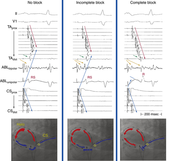
1 Atrial Activation Sequence During Atrial Pacing
Normally, during atrial pacing at a CL of 600 milliseconds from the CS os, one wavefront propagates from the CS pacing site in a clockwise direction through the CTI to the low lateral RA. The other wavefront from the CS os ascends up the atrial septum to the high RA in a counterclockwise direction, with resulting collision of wavefronts at the upper part of the lateral RA (the exact location of wavefront collision depends on the relative conduction velocities of the RA and the CTI) and generating an atrial activation sequence with a chevron pattern (see Fig. 12-16). Clockwise CTI block is indicated by the observation of a purely descending wavefront at the lateral wall down to the CTI (proximal-to-distal activation sequence on the Halo catheter positioned around the tricuspid annulus) when pacing from the CS os (i.e., pacing of the septal side of the ablation line; see Video 9).  This block is associated with marked prolongation of the CTI conduction duration (i.e., the interval from the CS os to the low lateral RA; see Fig. 12-16). Incomplete clockwise CTI block is said to occur when a descending wavefront at the lateral RA wall still allows the lateral part of the CTI to be activated from the CS os in a clockwise direction across the CTI but at a slower conduction velocity, resulting in displacement of collision of the clockwise and counterclockwise wavefronts to the lower part of lateral RA. The distal bipole of the Halo catheter (Halo 1-2) at the lateral part of the CTI is activated slightly before or at the same time as bipole Halo 3-4, situated more laterally (see Fig. 12-16).2,6
It is important to recognize that monitoring only the atrial activation sequence of the RA lateral wall recorded by the Halo catheter during CS pacing can lead to diagnostic errors in a large percentage of patients. This is because of the inability to detect very slow residual isthmus conduction that allows the wavefront propagating in an opposite direction to reach the ablation line earlier than the transisthmus conduction. Theoretically, slow but persistent isthmus conduction that can be confined within the ablation line or part of the isthmus distant from an area mapped by the multipolar catheter can therefore be misdiagnosed, no matter how closely the distal tip of the Halo catheter is placed to the ablation line, or even if the Halo catheter is positioned across the ablation line.2,6
During low lateral RA pacing prior to ablation, the RA activation sequence (with intact counterclockwise CTI conduction) exhibits two ascending wavefronts (septal and lateral) leading to impulse collision at the high lateral wall. The caudocranial activation of the RA septum following counterclockwise propagation of the paced wavefront through the CTI results in atrial activation in the CS os preceding that in the HB region (Fig. 12-17). Furthermore, intact conduction through the CTI permits the paced wavefront to proceed rapidly to activate the LA from below (and CS activation propagates in a proximal-to-distal direction), thus giving rise to an inverted P wave in the inferior leads. Counterclockwise CTI block is indicated by the observation of a single ascending wavefront at the lateral wall (distal-to-proximal Halo sequence) followed by a completely descending wavefront at the septum to reach the CS os. Therefore, compared with baseline, counterclockwise CTI block is associated with inversion of the direction of the septal activation from ascending to descending. Furthermore, the CS os electrogram is activated after the high RA and the HB region (see Fig. 12-17). Additionally, counterclockwise conduction block in the CTI forces the wavefront to activate the LA from above via the Bachmann bundle—and CS activation propagates in a distal-to-proximal direction—and gives rise to a different P wave morphology, with the terminal portion positive in the inferior leads.2,6
2 Transisthmus Conduction Interval
The transisthmus conduction interval is measured during CS os or low lateral RA pacing; it is equal to the interval from the stimulus artifact from one side of the isthmus to the atrial electrogram recorded on the contralateral side. Prolongation of this interval by more than 50% (or to an absolute value of 150 milliseconds or more) suggests CTI block (see Fig. 12-16). This criterion has sensitivity and negative predictive values of 100%. However, the specificity and positive predictive values are less than 90%.
3 Double Potentials
Double potentials, separated by an isoelectric interval of 30 milliseconds or longer, straddle a line of block. Double potentials along the ablation line across the CTI are generally considered the gold standard for determining complete bidirectional block (see Fig. 12-16). When there is a gap in a line of block, the isoelectric period between the double potentials shortens the closer the electrograms are to the gap. At the gap, in the line of block, double potentials are no longer present, and the electrogram is typically long and fractionated but can also be discrete. When the interval between the double potentials is more than 110 milliseconds, CTI block is present. When that interval is less than 90 milliseconds, complete bidirectional block is absent.
This technique is probably more difficult to perform than the classic activation mapping technique, mainly because of the ambiguity of electrogram interpretation along the ablation line, especially after extensive ablation attempts. When double potentials cannot be visualized, the interval between the pair of electrograms immediately on either side of the line of block (the [DP + 1] interval) when pacing immediately septal and lateral to the line of block can be used as an alternative method for verifying complete bidirectional CTI block. This technique requires positioning of a duodecapolar catheter around the tricuspid annulus while extending the catheter tip inside the CS, so that the catheter straddles the CTI and provides recording and pacing from the medial and lateral aspects of the isthmus. The [DP + 1] interval cutoff of 140 milliseconds seems to have better or equal sensitivity, specificity, and positive predictive values than other criteria. Nevertheless, it is still very difficult to distinguish incomplete block with very slow conduction from complete block. Additionally, gaps along the ablation line remote from the duodecapolar catheter would result in a [DP + 1] interval that is long in the absence of complete CTI block.44
4 Unipolar Electrogram Configuration
The morphology of the unfiltered unipolar recording indicates the direction of wavefront propagation. Positive deflections (R waves) are generated by propagation toward the recording electrode; negative deflections (QS complexes) are generated by propagation away from the electrode. During proximal CS pacing, the unfiltered unipolar signals recorded from the CTI typically demonstrate an RS configuration as the paced impulse propagates clockwise across the isthmus. In addition, because atrial depolarization along the CTI occurs sequentially in the clockwise direction, the polarity of the initial depolarization is the same from each pair of recording electrodes when using unfiltered unipolar recording on the CTI. When complete clockwise CTI block is achieved, depolarization of the electrode just medial to the line of block retains its original polarity, but its morphology changes to a single positive deflection (monophasic R wave) because the recording site becomes a dead end for impulse conduction. Conversely, atrial tissue lateral to the line of block is depolarized from the counterclockwise direction, which is opposite to the original direction of depolarization. Accordingly, the polarity of the atrial electrograms on the CTI lateral to the line of block reverses (see Fig. 12-16). The same maneuver can be performed with pacing from the low lateral RA to evaluate counterclockwise CTI block.
Some studies have suggested that bipolar electrogram morphology could also be used for verification of the presence of CTI block. However, it is important to emphasize that bipolar recordings predominantly reflect local activation time; signal subtraction used to create a bipolar signal largely eliminates morphology information at either electrode. Nevertheless, bipolar electrogram polarity reversal can indicate a reversed wavefront direction that has been used in addition to the activation sequence for verifying bidirectional CTI block (see Fig. 12-16).
5 Differential Pacing
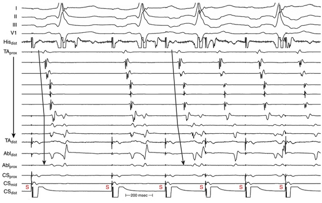
Using the same principle, the local activation time at the CS os electrode during fixed-rate pacing performed from the low lateral and midlateral RA can be used for evaluation of counterclockwise CTI block. Normally (with intact isthmus conduction), CS os activation occurs via propagation of the paced wavefront across the CTI in a counterclockwise direction. Therefore, CS os activation occurs earlier during pacing from the low lateral RA compared with the midlateral RA because the low lateral RA is anatomically closer to the CS os. In contrast, when counterclockwise CTI block is present, CS os activation occurs via the wavefront propagating in a clockwise direction up the RA lateral wall, over the RA roof, and then down the septum (see Fig. 12-17). Consequently, CS os activation occurs earlier during pacing from the midlateral compared with the low lateral RA because the length of the detour is shortened by pacing from the midlateral RA.
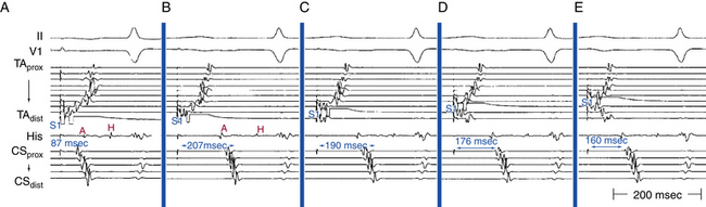
6 Rate-Dependent Isthmus Block
This maneuver helps distinguish isthmus block from long local conduction delay across the isthmus. With incomplete CTI block, activation of the low lateral RA during CS os pacing can be delayed, but activation can still occur via the CTI at the same time or just earlier than the wavefront coming to the low lateral RA from the counterclockwise direction. Increasing the pacing rate results in decremental conduction across the now diseased isthmus and causes further delay in activation of the low lateral RA (Fig. 12-18). In contrast, when complete CTI block is present, the lateral RA is activated in a counterclockwise direction across the atrial septum and RA roof. Because these atrial regions conduct nondecrementally, pacing at faster rates should not change the timing of low lateral RA activation significantly, as long as the pacing CL is longer than atrial refractoriness. The same maneuver can be performed with pacing from the low lateral RA to evaluate counterclockwise CTI block.
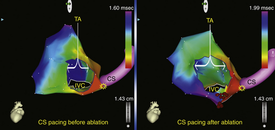
7 Electroanatomical Mapping
Electroanatomical 3-D activation mapping can be used to verify CTI block. When clockwise block in the CTI is achieved, proximal CS pacing results in an activation wavefront propagating in a counterclockwise fashion, with the latest activation in the CTI immediately lateral to the ablation line (Fig. 12-19). When conduction across the CTI is still intact, CS pacing produces an activation wavefront that propagates rapidly through the CTI, with the anterolateral RA wall activated last. Similar maps can be generated during low lateral RA pacing to confirm counterclockwise block in the CTI. Activation maps can also be evaluated for the presence of gaps in the ablation lines, as indicated by the early breakthroughs from the ablation line. However, following CTI ablation, the local electrograms at the ablation line can be complex—with double, triple, or fragmented potentials and unclear local activation time—and electroanatomical activation mapping can be challenging.
Outcome
With the availability of precise catheter locator systems, more effective ablation tools, and accurate endpoints for ablation, the inability to create complete CTI block and to eliminate recurrences of CTI-dependent AFL successfully is unusual in contemporary practice. Acute success rate of ablation of typical AFL is higher than 90% when large-tip or irrigated RF catheters are used.45,46 A repeat ablation procedure is performed in 5% to 15% of patients, and the long-term success rate in preventing recurrent AFL is 97%.45 Advances in AFL ablation technologies have had less effect on short-term success rates than on reducing AFL recurrences. On the other hand, the use of the more stringent endpoint of bidirectional block significantly reduces the AFL recurrence rate. For patients in whom typical AFL recurs after ablation, conduction through the CTI is usually responsible. Presumably, such recurrences reflect a failure to achieve bidirectional CTI block during the initial procedure, incorrect initial assessment of bidirectional block, or resumption of conduction across an initially blocked isthmus. The incidence of AFL recurrence does not increase beyond 1 to 6 months of follow-up, a finding suggesting that if recovery of isthmus conduction is going to occur, it will have done so by 6 months.46
Serious complications associated with AFL ablation are rare (0.4%) and include AV block (most common, 0.2%), cardiac tamponade, groin hematoma, transient inferior ST segment elevation or acute occlusion of the right coronary artery,47 thromboembolic complications, and ventricular tachycardia.45
Following AFL ablation, AF can develop in approximately 20% to 30% (with short-term follow-up, approximately 1 year) and in up to 82% (with long-term follow-up, approximately 4 years) of patients with or without a prior history of AF.2,6,48 It appears that AFL is often an early marker of atrial electrical disease that frequently progresses to AF even after curative treatment for AFL. This has led some investigators to advocate ablation of AF at the same time of AFL ablation.49 In a meta-analysis, over an average follow-up of 16 months, AF occurred in 23.1% of patients with no preablation history of AF and in 52.7% of patients with a history of AF, despite successful AFL ablation. The occurrence of AF was not influenced by the ablation technology or procedural endpoints. This finding has serious implications for patient selection, long-term arrhythmia-free success rates, postprocedure antiarrhythmic drug use, and postprocedure anticoagulation. Because AF predating ablation of AFL is very likely to recur, thus limiting the ability to discontinue antiarrhythmic medications or anticoagulation in many patients, the potential benefits of ablation of only AFL should be seriously scrutinized.46
1. Asirvatham S.J. Correlative anatomy and electrophysiology for the interventional electrophysiologist: right atrial flutter. J Cardiovasc Electrophysiol. 2009;20:113-122.
2. Waldo A.L., Atiezna F. Atrial flutter: mechanisms, features, and management. In: Zipes D.P., Jalife J., editors. Cardiac electrophysiology: from cell to bedside. ed 5. Philadelphia: Saunders; 2009:567-576.
3. Tai C.T., Chen S.A. Cavotricuspid isthmus: anatomy, electrophysiology, and long-term outcome of radiofrequency ablation. Pacing Clin Electrophysiol. 2009;32:1591-1595.
4. Saremi F., Pourzand L., Krishnan S., et al. Right atrial cavotricuspid isthmus: anatomic characterization with multi-detector row CT. Radiology. 2008;247:658-668.
5. Waldo A.L. Atrial flutter: from mechanism to treatment. In: Camm A.J., editor. Clinical approaches to tachyarrhythmias. Armonk, NY: Futura; 2001:1-56.
6. Feld G., Srivatsa U., Hoppe B. Ablation of isthmus-dependent atrial flutters. In: Huang S.K.S., Wood M., editors. Catheter ablation of cardiac arrhythmias. Philadelphia: Saunders; 2006:195-218.
7. Santucci P.A., Varma N., Cytron J., et al. Electroanatomic mapping of postpacing intervals clarifies the complete active circuit and variants in atrial flutter. Heart Rhythm. 2009;6:1586-1595.
8. Anselme F. Macroreentrant atrial tachycardia: pathophysiological concepts. Heart Rhythm. 2008;5(Suppl):S18-S21.
9. Huang J.L., Tai C.T., Lin Y.J., et al. Right atrial substrate properties associated with age in patients with typical atrial flutter. Heart Rhythm. 2008;5:1144-1151.
10. Feld G.K., Mollerus M., Birgersdotter-Green U., et al. Conduction velocity in the tricuspid valve-inferior vena cava isthmus is slower in patients with type I atrial flutter compared to those without a history of atrial flutter. J Cardiovasc Electrophysiol. 1997;8:1338-1348.
11. Morita N., Kobayashi Y., Horie T., et al. The undetermined geometrical factors contributing to the transverse conduction block of the crista terminalis. Pacing Clin Electrophysiol. 2009;32:868-878.
12. Tai C.T., Chen S.A. Conduction barriers of atrial flutter: relation to the anatomy. Pacing Clin Electrophysiol. 2008;31:1335-1342.
13. Granada J., Uribe W., Chyou P.H., et al. Incidence and predictors of atrial flutter in the general population. J Am Coll Cardiol. 2000;36:2242-2246.
14. Blomstrom-Lundqvist C., Scheinman M.M., Aliot E.M., et al. ACC/AHA/ESC guidelines for the management of patients with supraventricular arrhythmias—executive summary: a report of the American College of Cardiology/American Heart Association Task Force on Practice Guidelines and the European Society of Cardiology Committee for Practice Guidelines (writing committee to develop guidelines for the management of patients with supraventricular arrhythmias). Circulation. 2003;108:1871-1909.
15. Medi C., Kalman J.M. Prediction of the atrial flutter circuit location from the surface electrocardiogram. Europace. 2008;10:786-796.
16. Josephson M.E. Atrial flutter and fibrillation. In: Josephson M.E., editor. Clinical cardiac electrophysiology. ed 4. Philadelphia: Lippincott Williams & Wilkins; 2008:285-338.
17. Miyazaki H., Stevenson W.G., Stephenson K., et al. Entrainment mapping for rapid distinction of left and right atrial tachycardias. Heart Rhythm. 2006;3:516-523.
18. Deo R., Berger R. The clinical utility of entrainment pacing. J Cardiovasc Electrophysiol. 2009;20:466-470.
19. Zhang S., Younis G., Hariharan R., et al. Lower loop reentry as a mechanism of clockwise right atrial flutter. Circulation. 2004;109:1630-1635.
20. Bochoeyer A., Yang Y., Cheng J., et al. Surface electrocardiographic characteristics of right and left atrial flutter. Circulation. 2003;108:60-66.
21. Garan H. Atypical atrial flutter. Heart Rhythm. 2008;5:618-621.
22. Higa S., Tai C.T., Lin Y.J., et al. Focal atrial tachycardia: new insight from noncontact mapping and catheter ablation. Circulation. 2004;109:84-91.
23. Cosio F.G., Pastor A., Nunez A., Giocolea A. Catheter ablation of typical atrial flutter. In: Zipes D.P., Haissaguerre M., editors. Catheter ablation of arrhythmias. Armonk, NY: Futura; 2002:131-152.
24. Nakao M., Saoudi N. More on isthmus anatomy for safety and efficacy. J Cardiovasc Electrophysiol. 2005;16:409-410.
25. Calkins H., Brugada J., Packer D.L., et al. HRS/EHRA/ECAS expert consensus statement on catheter and surgical ablation of atrial fibrillation: recommendations for personnel, policy, procedures and follow-up. A report of the Heart Rhythm Society (HRS) Task Force on Catheter and Surgical Ablation of Atrial Fibrillation. Heart Rhythm. 2007;4:816-861.
26. Finlay M., Sawhney V., Schilling R., et al. Uninterrupted warfarin for periprocedural anticoagulation in catheter ablation of typical atrial flutter: a safe and cost-effective strategy. J Cardiovasc Electrophysiol. 2010;21:150-154.
27. Marrouche N.F., Schweikert R., Saliba W., et al. Use of different catheter ablation technologies for treatment of typical atrial flutter: acute results and long-term follow-up. Pacing Clin Electrophysiol. 2003;26:743-746.
28. Gula L.J., Redfearn D.P., Veenhuyzen G.D., et al. Reduction in atrial flutter ablation time by targeting maximum voltage: results of a prospective randomized clinical trial. J Cardiovasc Electrophysiol. 2009;20:1108-1112.
29. Ozaydin M., Tada H., Chugh A., et al. Atrial electrogram amplitude and efficacy of cavotricuspid isthmus ablation for atrial flutter. Pacing Clin Electrophysiol. 2003;26:1859-1863.
30. Redfearn D.P., Skanes A.C., Gula L.J., et al. Cavotricuspid isthmus conduction is dependent on underlying anatomic bundle architecture: observations using a maximum voltage-guided ablation technique. J Cardiovasc Electrophysiol. 2006;17:832-838.
31. Subbiah R.N., Gula L.J., Krahn A.D., et al. Rapid ablation for atrial flutter by targeting maximum voltage-factors associated with short ablation times. J Cardiovasc Electrophysiol. 2007;18:612-616.
32. Ventura R., Rostock T., Klemm H.U., et al. Catheter ablation of common-type atrial flutter guided by three-dimensional right atrial geometry reconstruction and catheter tracking using cutaneous patches: a randomized prospective study. J Cardiovasc Electrophysiol. 2004;15:1157-1161.
33. Hindricks G., Willems S., Kautzner J., et al. Effect of electroanatomically guided versus conventional catheter ablation of typical atrial flutter on the fluoroscopy time and resource use: a prospective randomized multicenter study. J Cardiovasc Electrophysiol. 2009;20:734-740.
34. Gami A.S., Edwards W.D., Lachman N., et al. Electrophysiological anatomy of typical atrial flutter: the posterior boundary and causes for difficulty with ablation. J Cardiovasc Electrophysiol. 2010;21:144-149.
35. Lo L.W., Tai C.T., Lin Y.J., et al. Characteristics of the cavotricuspid isthmus in predicting recurrent conduction in the long-term follow-up. J Cardiovasc Electrophysiol. 2009;20:39-43.
36. Atiga W.L., Worley S.J., Hummel J., et al. Prospective randomized comparison of cooled radiofrequency versus standard radiofrequency energy for ablation of typical atrial flutter. Pacing Clin Electrophysiol. 2002;25:1172-1178.
37. Schreieck J., Zrenner B., Kumpmann J., et al. Prospective randomized comparison of closed cooled-tip versus 8-mm-tip catheters for radiofrequency ablation of typical atrial flutter. J Cardiovasc Electrophysiol. 2002;13:980-985.
38. Boll S., Dang L., Scharf C. Linear ablation with duty-cycled radiofrequency energy at the cavotricuspid isthmus. Pacing Clin Electrophysiol. 2010;33:444-450.
39. Erdogan A., Guettler N., Doerr O., et al. Randomized comparison of multipolar, duty-cycled, bipolar-unipolar radiofrequency versus conventional catheter ablation for treatment of common atrial flutter. J Cardiovasc Electrophysiol. 2010;21:1109-1113.
40. Timmermans C., Ayers G.M., Crijns H.J., Rodriguez L.M. Randomized study comparing radiofrequency ablation with cryoablation for the treatment of atrial flutter with emphasis on pain perception. Circulation. 2003;107:1250-1252.
41. Collins N.J., Barlow M., Varghese P., Leitch J. Cryoablation versus radiofrequency ablation in the treatment of atrial flutter trial (CRAAFT). J Interv Card Electrophysiol. 2006;16:1-5.
42. Kuniss M., Vogtmann T., Ventura R., et al. Prospective randomized comparison of durability of bidirectional conduction block in the cavotricuspid isthmus in patients after ablation of common atrial flutter using cryothermy and radiofrequency energy: the CRYOTIP study. Heart Rhythm. 2009;6:1699-1705.
43. Tada H., Oral H., Ozaydin M., et al. Randomized comparison of anatomic and electrogram mapping approaches to ablation of typical atrial flutter. J Cardiovasc Electrophysiol. 2002;13:662-666.
44. Zambito P.E., Palma E.C. DP+1: another simple endpoint for atrial flutter ablation. J Cardiovasc Electrophysiol. 2008;19:10-13.
45. Morady F. Catheter ablation of supraventricular arrhythmias: state of the art. J Cardiovasc Electrophysiol. 2004;15:124-139.
46. Perez F.J., Schubert C.M., Parvez B., et al. Long-term outcomes after catheter ablation of cavo-tricuspid isthmus dependent atrial flutter: a meta-analysis. Circ Arrhythm Electrophysiol. 2009;2:393-401.
47. Mykytsey A., Kehoe R., Bharati S., et al. Right coronary artery occlusion during RF ablation of typical atrial flutter. J Cardiovasc Electrophysiol. 2010;21:818-821.
48. Ellis K., Wazni O., Marrouche N., et al. Incidence of atrial fibrillation post-cavotricuspid isthmus ablation in patients with typical atrial flutter: left-atrial size as an independent predictor of atrial fibrillation recurrence. J Cardiovasc Electrophysiol. 2007;18:799-802.
49. Navarrete A., Conte F., Moran M., et al. Ablation of atrial fibrillation at the time of cavotricuspid isthmus ablation in patients with atrial flutter without documented atrial fibrillation derives a better long-term benefit. J Cardiovasc Electrophysiol. 2011;22:34-38.