Ultrasound
Over the past 20 years, bedside ultrasound has become an indispensible tool in the emergency department (ED). It has enabled physicians to make a rapid diagnosis at the bedside and formulate a plan of care. Perhaps most importantly, ultrasound has revolutionized procedures performed in the ED. Use of ultrasound gives the physician the advantage of viewing the anatomy and directly imaging the procedure while it is being performed. Procedures that had previously been performed “blindly” can now be performed with the added assurance of monitoring the procedure while it is in progress. This has resulted in greater safety in both common and uncommon procedures.1,2
Physics
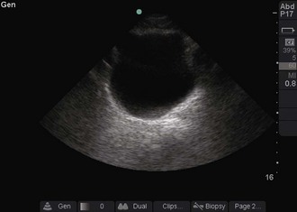
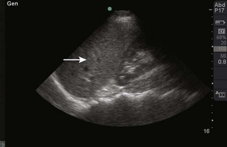
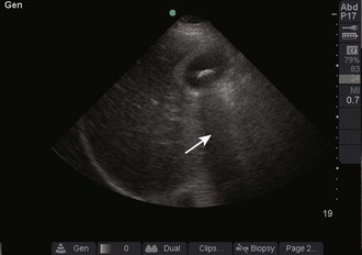
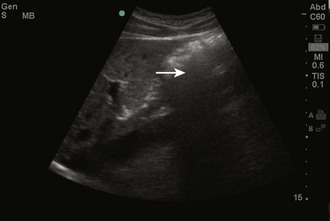
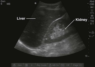
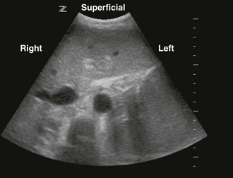
Objects in the body that are liquid or water-like, such as a full bladder, reflect very few sound waves and allow most of the energy to pass through them. These objects are presented on-screen as black by ultrasound and are described as anechoic, without echoes (Fig. 66-1). Conversely, objects that are dense and have very little water content, such as bones, reflect almost all the sound waves back. These objects are presented on-screen as white by ultrasound and are described as hyperechoic (i.e., producing a lot of echoes) (Fig. 66-2). Objects that lie between these two extremes are varying shades of gray, depending on the water content of the object. For example, the liver contains a large amount of blood, a water-like substance, but is not completely liquid and appears on-screen as a dark gray (Fig. 66-3). An object that contains less water but is not completely solid would appear as a lighter shade of gray.
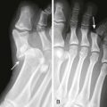
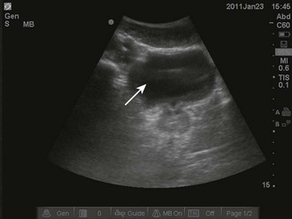
These properties of objects also account for two important artifacts. Acoustic shadowing is an artifact that is encountered when dealing with hyperechoic objects. These objects reflect almost all the sound waves back to the transducer. As a result, the ultrasound machine “senses” an absence of information deep to the hyperechoic object. This absence of information is represented by a strong, dark vertical line emanating deep to the object (Fig. 66-4). This type of shadowing is referred to as a “clean shadow.” Although this shadow can be frustrating to the sonographer when attempting to obtain the best image possible, classically, when imaging over the ribs, it can also be helpful in identifying hyperechoic objects, such as gallstones or foreign bodies.
In contrast to a “clean shadow,” the presence of air may create a phenomenon known as “dirty shadowing” (Fig. 66-5). Air causes the ultrasound beam to scatter and creates a hazy, gray appearance on the image. This can be an anticipated finding, such as when viewing bowel gas within the abdomen, or an indication of an abnormality, such as when viewing gas within subcutaneous tissue.
Acoustic enhancement, or an acoustic window, is the effect created by an anechoic object. As noted earlier, sound waves pass through anechoic objects well and therefore lose less of their energy. This enables more ultrasonic energy to be available when the sound reaches the object on the other side of the fluid. This results in a brighter, clearer image immediately behind the fluid-filled object. As an example, a full bladder enables a clearer image of the pelvic organs (Fig. 66-6).
Indications and Contraindications
Although vascular access was one of the first uses of ultrasound in ED procedures, the list of procedures that can be facilitated by ultrasound is growing rapidly and continuously (Box 66-1). Even in cases in which the procedure cannot be directly observed with ultrasound, bedside ultrasound can frequently be used to diagnose the abnormality and to plan the approach for the procedure.
Equipment
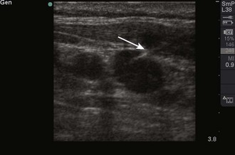
High-frequency sound waves do not penetrate very far into the tissue but provide excellent resolution. A linear, or vascular, transducer and an intracavitary transducer are examples of specific types of high-frequency transducers (Figs. 66-7 and 66-8). Examples of types of examinations that are best evaluated with a high-frequency transducer are central or peripheral vascular access, evaluation of the pleura for pneumothorax, and evaluation of soft tissue for an abscess or foreign body. These examinations rely on a high degree of resolution (Fig. 66-9).
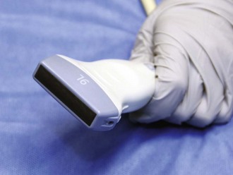
Figure 66-7 Linear, or vascular, transducer.
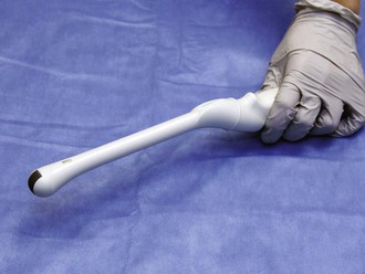
Figure 66-8 Intracavitary transducer.
Low-frequency sound waves penetrate farther into tissues but do not provide as much resolution as high frequency does. Curvilinear, phased-array, and microconvex transducers are examples of specific types of low-frequency transducers (Figs. 66-10 and 66-11). They are distinguished from each other by the shape of the footprint of the transducer, the part that directly touches the patient, and by the layout of crystals in the tip of the transducer. Examples of the types of examinations that are best evaluated with a low-frequency transducer are evaluation of the pleural or peritoneal cavities for fluid drainage, evaluation of the bladder for aspiration or suprapubic catheter placement, and evaluation of the pericardium for pericardiocentesis. These examinations are not as dependent on resolution but typically require greater penetration (Fig. 66-12).
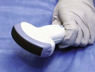
Figure 66-10 Curvilinear transducer.
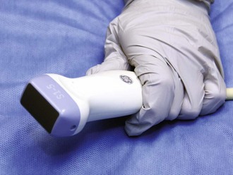
Figure 66-11 Phased-array transducer.
General Approach
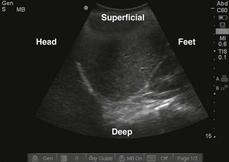
Once the correct transducer has been selected, evaluate the area of interest. This step is key when evaluating the nature of the pathology. For example, understanding the size and position of a subcutaneous abscess and the surrounding anatomy is essential. Determining the correct orientation of objects on the screen can be challenging, but it is crucial for success with ultrasound-guided procedures. All transducers have a dot or mark on one side (Fig. 66-13). This mark corresponds to an indicator on the left-hand side of the screen (Fig. 66-14). When the indicator on the transducer is pointing toward the patient’s right side, a transverse image will be generated (Fig. 66-15). Objects on the right of the screen are closer to the patient’s left side and objects on the left side, near the on-screen indicator, are closer to the patient’s right side. Objects near the top of the screen are closer to the skin and objects near the bottom of the screen are deeper in the body. When the indicator is turned toward the patient’s head, a longitudinal image is generated (Fig. 66-16). Objects on the right side of the screen are closer to the patient’s feet and objects on the left side of the screen (near the on-screen indicator) are closer to the patient’s head. As with the transverse image, objects near the top of the screen are closer to the skin surface and objects at the bottom of the screen are deeper in the body.
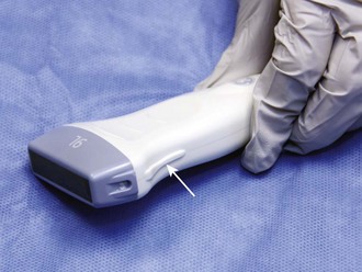
Figure 66-13 Indicator on the transducer (arrow).
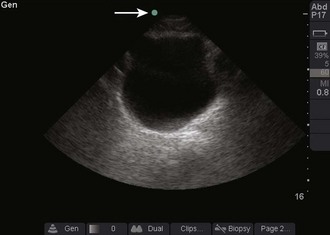
Figure 66-14 Indicator on-screen (arrow), which corresponds to the indicator on the side of the transducer.
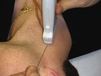
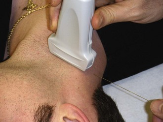
When direct visualization is desired, the orientation of the needle to the transducer must be considered. When the needle is introduced at the midpoint of the transducer in the transverse approach, the tip of the needle may be difficult to visualize (Fig. 66-17). In this orientation the operator may have difficulty following the tip of the needle because only a small portion of the needle intersects the ultrasound beam at any given time (Figs. 66-18 and 66-19). Conversely, when the needle is introduced from either end of the transducer, the needle can be visualized in its entirety (Figs. 66-20 and 66-21). However, slight movement of the transducer may result in “losing” the view of the needle. Consider each potential approach in the context of the particular procedure.
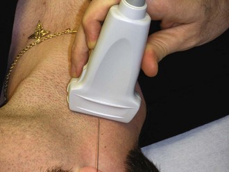
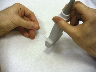
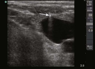
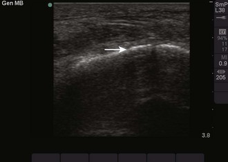
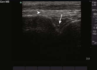
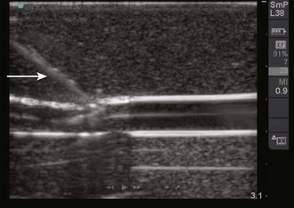
Figure 66-19 Real-time image of the needle as it approaches the vein. The needle (arrow) is seen as a hyperechoic object with strong shadowing extending behind it. The portion of the needle seen will correspond to the portion of the needle that is underlying the transducer, as shown in Figure 66-18.
The oblique approach is a combination of the transverse and longitudinal approaches. Primarily, this has been described for central venous access but can also be applied to other procedures as well.3 In this method, place the transducer on an oblique axis to the target object (Fig. 66-22). This allows an oblique view of the target object while enabling the operator to introduce the needle along the long axis of the transducer (Fig. 66-23).
Complications
In general, the incidence of complications should be reduced with the use of ultrasound, but complications may occur even when performed by an experienced sonographer. Complications may be related to one of several factors. To maximize success, obtain an optimal image of the structure in question. Evaluate the anatomic relationships to ensure that the target object (e.g., the femoral vein versus the femoral artery) is correctly identified and pursued. Once the procedure begins, pay constant attention to the orientation and location of the needle. Errors, including inadvertent arterial puncture, can occur when the position of the tip of the needle is not closely followed.4,5 Techniques to minimize these errors are addressed in the individual chapters.
References
1. Leung, J, Duffy, M, Finckh, A. Real-time ultrasonographically-guided internal jugular vein catheterization in the emergency department increases success rates and reduces complications: a randomized, prospective study. Ann Emerg Med. 2006;48:540–547.
2. Lyon, M, Blaivas, M. Intraoral ultrasound in the diagnosis and treatment of suspected peritonsillar abscess in the emergency department. Acad Emerg Med. 2008;12:85–88.
3. Phelan, M, Hagerty, D. The oblique view: an alternative approach for ultrasound-guided central line placement. J Emerg Med. 2009;37:403–408.
4. Blaivas, M. Video analysis of accidental arterial cannulation with dynamic ultrasound guidance for central venous access. J Ultrasound Med. 2009;28:1239–1244.
5. Blaivas, M, Adhikari, S. An unseen danger: frequency of posterior vessel wall penetration by needles during attempts to place internal jugular vein central catheters using ultrasound guidance. Crit Care Med. 2009;37:2345–2349.