Storage and Delivery of Medical Gases
After reading this chapter you will be able to:
 Describe how medical gases and gas mixtures are produced.
 Discuss the clinical applications for medical gases and gas mixtures.
 Distinguish between gaseous and liquid storage methods.
 Calculate the duration of remaining contents of a compressed oxygen cylinder.
 Calculate the duration of remaining contents of a liquid oxygen cylinder.
 Describe how to store, transport, and use compressed gas cylinders properly.
 Distinguish between gas supply systems.
 Describe what to do if a bulk oxygen supply system fails.
 Differentiate among safety systems that apply to various equipment connections.


 Identify and correct common malfunctions of gas delivery equipment.
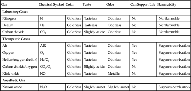
There are many commercially produced gases, but only a few are used medically (Table 37-1). Medical gases are classified as laboratory gases, therapeutic gases, or anesthetic gases. Laboratory gases are used for equipment calibration and diagnostic testing. Therapeutic gases are used to relieve symptoms and improve oxygenation of patients with hypoxemia. Anesthetic gases are combined with oxygen (O2) to provide anesthesia during surgery. It is important for RTs to be familiar with all aspects of gases used in the clinical setting, especially the chemical symbols, physical characteristics, ability to support life, and fire risk. In regard to fire risk, medical compressed gases are classified as either nonflammable (do not burn), nonflammable but supportive of combustion (also termed oxidizing), or flammable (burns readily, potentially explosive).1 Of the gases listed in Table 37-1, the focus of this chapter is on the therapeutic gases.
TABLE 37-1
Physical Characteristics of Medical Gases
| Gas | Chemical Symbol | Color | Taste | Odor | Can Support Life | Flammability |
| Laboratory Gases | ||||||
| Nitrogen | N | Colorless | Tasteless | Odorless | No | Nonflammable |
| Helium | He | Colorless | Tasteless | Odorless | No | Nonflammable |
| Carbon dioxide | CO2 | Colorless | Slightly acidic | Odorless | No | Nonflammable |
| Therapeutic Gases | ||||||
| Air | AIR | Colorless | Tasteless | Odorless | Yes | Supports combustion |
| Oxygen | O2 | Colorless | Tasteless | Odorless | Yes | Supports combustion |
| Helium/oxygen (heliox) | He/O2 | Colorless | Tasteless | Odorless | Yes | Supports combustion |
| Carbon dioxide/oxygen | CO2/O2 | Colorless | Slightly acidic | Odorless | No | Supports combustion |
| Nitric oxide | NO | Colorless | Tasteless | Metallic | No | Supports combustion |
| Anesthetic Gas | ||||||
| Nitrous oxide | N2O | Colorless | Slightly sweet | Slightly sweet | No | Supports combustion |
Characteristics of Medical Gases
Oxygen
Characteristics
O2 is a colorless, odorless, transparent, and tasteless gas.1 It exists naturally as free molecular O2 and as a component of a host of chemical compounds. O2 constitutes almost 50% by weight of the earth’s crust and occurs in all living matter in combination with hydrogen as water. At standard temperature, pressure, and dry (STPD), O2 has a density of 1.429 g/L, being slightly heavier than air (1.29 g/L). O2 is not very soluble in water. At room temperature and 1 atm pressure, only 3.3 ml of O2 dissolves in 100 ml of water.
O2 is nonflammable, but it greatly accelerates combustion. Burning speed increases with either (1) an increase in O2 percentage at a fixed total pressure or (2) an increase in total pressure of O2 at a constant gas concentration. Both O2 concentration and partial pressure influence the rate of burning.2
Production
O2 is produced through one of several methods. Chemical methods for producing small quantities of O2 include electrolysis of water and decomposition of sodium chlorate (NaClO3). Most large quantities of medical O2 are produced by fractional distillation of atmospheric air.1 Small quantities of concentrated O2 are produced by physical separation of O2 from air.
Fractional Distillation
The resulting mixture of liquid O2 and nitrogen (N, N2) is heated slowly in a distillation tower. N2, with its boiling point of 195.8° C (320.5° F), escapes first, followed by the trace gases of argon, krypton, and xenon. The remaining liquid O2 is transferred to specially insulated cryogenic (low-temperature) storage cylinders. An alternative procedure is to convert O2 directly to gas for storage in high-pressure metal cylinders. These methods produce O2 that is approximately 99.5% pure. The remaining 0.5% is mostly N2 and trace argon. U.S. Food and Drug Administration (FDA) standards require an O2 purity of at least 99.0%.3
Physical Separation
Two methods are used to separate O2 from air.4 The first method entails use of molecular “sieves” composed of inorganic sodium aluminum silicate pellets. These pellets absorb N2, “trace” gases, and water vapor from the air, providing a concentrated mixture of more than 90% O2 for patient use. The second method entails use of a vacuum to pull ambient air through a semipermeable plastic membrane. The membrane allows O2 and water vapor to pass through at a faster rate than N2 from ambient air. This system can produce an O2 mixture of approximately 40%. These devices, called oxygen concentrators, are used primarily for supplying low-flow O2 in the home care setting. For this reason, details about the principles of operation and appropriate use are discussed in Chapter 51.
Air
Atmospheric air is a colorless, odorless, naturally occurring gas mixture that consists of 20.95% O2, 78.1% N2, and approximately 1% “trace” gases, mainly argon. At STPD, the density of air is 1.29 g/L, which is used as the standard for measuring specific gravity of other gases. O2 and N2 can be mixed to produce a gas with an O2 concentration equivalent to that of air. Medical-grade air usually is produced by filtering and compressing atmospheric air.1,5
Figure 37-1 shows a typical large medical air compressor system. In these systems, an electrical motor is used to power a piston in a compression cylinder. On its downstroke, the piston draws air through a filter system with an inlet valve. On its upstroke, the piston compresses the air in the cylinder (closing the inlet valve) and delivers it through an outlet valve to a reservoir tank. Air from the reservoir tank is reduced to the desired working pressure by a pressure-reducing valve before being delivered to the piping system.
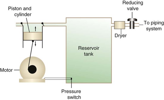
For medical gas use, air must be dry and free of oil or particulate contamination.5 The most common method used for drying air is cooling to produce condensation. For avoidance of oil or particulate contamination, medical air compressors have air inlet filters and polytetrafluoroethylene (Teflon) piston rings as opposed to oil lubrication. Large medical air compressors must provide high flow (at least 100 L/min) at the standard working pressure of 50 pounds per square inch gauge (psig) for all equipment in use.
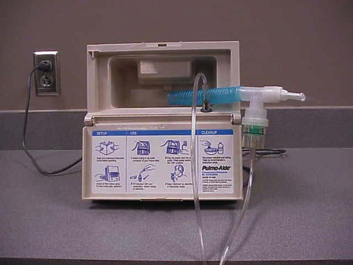
Smaller compressors (Figure 37-2) are available for bedside or home use. These compressors have a diaphragm or turbine that compresses the air and generally do not have a reservoir. This design limits the pressure and flow capabilities of these devices. For this reason, small compressors must never be used to power equipment that needs unrestricted flow at 50 psig, such as pneumatically powered ventilators (see Chapter 42). However, small diaphragm or turbine compressors are ideal for powering devices such as small-volume medication nebulizers (see Chapter 36).
Carbon Dioxide
At STPD, CO2 is a colorless and odorless gas with a specific gravity of 1.52 (approximately 1.5 times heavier than air).1 CO2 does not support combustion or maintain animal life. For medical use, CO2 usually is produced by heating limestone in contact with water. The gas is recovered from this process and liquefied by compression and cooling. The FDA purity standard for CO2 is 99%.3
Mixtures of O2 and 5% to 10% CO2 are occasionally used for therapeutic purposes as noted in Chapter 38. Therapeutic uses include the management of singultus (hiccups), prevention of the complete washout of CO2 during cardiopulmonary bypass, and regulation of pulmonary vascular pressures in some congenital heart disorders. However, CO2 mixtures are more commonly used for the calibration of blood gas analyzers (see Chapter 18) and for diagnostic purposes in the clinical laboratory.
Helium
Helium (He) is second only to hydrogen as the lightest of all gases; it has a density at STPD of 0.1785 g/L. He is odorless, tasteless, nonflammable, and chemically and physiologically inert. It is a good conductor of heat, sound, and electricity but is poorly soluble in water. Although He is present in small quantities in the atmosphere, it is commercially produced from natural gas through liquefaction to purity standards of at least 99%.3
He cannot support life, so breathing 100% He would cause suffocation and death. For therapeutic use, He must always be mixed with at least 20% O2. Heliox (a gas mixture of O2 and He) may be used clinically to manage severe cases of airway obstruction. Its low density decreases the work of breathing by making gas flow more laminar. He is discussed in more detail in Chapter 38.
 Rule of Thumb
Nitric Oxide
Nitric oxide (NO) is a colorless, nonflammable, toxic gas that supports combustion. It is produced by oxidation of ammonia at high temperatures in the presence of a catalyst. In combination with air, NO forms brown fumes of nitrogen dioxide (NO2). Together, NO and NO2 are strong respiratory irritants that can cause chemical pneumonitis and a fatal form of pulmonary edema. Exposure to high concentrations of NO alone can cause methemoglobinemia (see Chapter 11). High levels of methemoglobin can cause tissue hypoxia.
As discussed in Chapter 38, NO is approved by the FDA for use in the treatment of term and near-term infants for hypoxic respiratory failure. The American Academy of Pediatrics (AAP) has published a policy statement recommending the use of NO in the care of term and near-term infants when mechanical ventilation is failing because of hypoxic respiratory failure. The AAP suggests that NO be used before extracorporeal membrane oxygenation.6 A systemic review from the Cochrane database supports the recommendation that inhaled NO at 20 ppm may be beneficial in term and near-term infants who do not have a diaphragmatic hernia (see Chapter 31).7 The use of inhaled NO in the treatment of premature neonates with hypoxic respiratory failure does not improve outcomes and may increase the risk of intracranial hemorrhage.8
Nitrous Oxide
Nitrous oxide (N2O) is a colorless gas with a slightly sweet odor and taste that is used clinically as an anesthetic agent. Similar to O2, N2O can support combustion. However, N2O cannot support life and causes death if inhaled in pure form. For this reason, inhaled N2O must always be mixed with at least 20% O2. N2O is produced by thermal decomposition of ammonium nitrate.1
Long-term human exposure to N2O has been associated with a form of neuropathy. In addition, epidemiologic studies have linked chronic N2O exposure with an increased risk of fetal disorders and spontaneous abortion.1 On the basis of this knowledge, the National Institute for Occupational Safety and Health (a division of the Occupational Safety and Health Administration) has set an upper exposure limit for hospital operating rooms of 25 ppm N2O.1
Storage of Medical Gases
Gas Cylinders
The containers used to store and ship compressed or liquid medical gases are high-pressure cylinders. The design, manufacture, transport, and use of these cylinders are carefully controlled by both industrial standards and federal regulations. Gas cylinders are made of seamless steel and are classified by the U.S. Department of Transportation (DOT) according to their fabrication method. DOT type 3A cylinders are made from carbon steel, and DOT type 3AA containers are manufactured with a steel alloy tempered for higher strength.1
Markings and Identification
Medical gas cylinders are marked with metal stamping on the shoulders that supplies specific information (Figure 37-3).1,9 Although the exact location and order of these markings vary, the practitioner should be able to identify several key items of information.
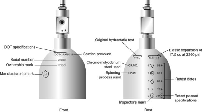
Safety tests are conducted on each cylinder every 5 or 10 years, as specified in DOT regulations.1,9 During these tests, cylinders are pressurized to five thirds of their service pressure. While the cylinder is under pressure, technicians measure cylinder leakage, expansion, and wall stress. The notation EE followed by a number indicates the elastic expansion of the cylinder in cubic centimeters under the test conditions. An asterisk (*) next to the test date indicates DOT approval for 10-year testing. A plus sign (+) means the cylinder is approved for filling to 10% greater than its service pressure. An approved cylinder with a service pressure of 2015 psi can be filled to approximately 2200 psi. After hydrostatic testing, cylinders are subjected to internal inspection and cleaning.
In addition to these permanent marks, all cylinders are color-coded and labeled for identification of their contents.1,10 Table 37-2 lists the color codes for medical gases as adopted by the Bureau of Standards of the U.S. Department of Commerce.11 For comparison, the color codes adopted by the Canadian Standards Association also are included. Color codes are not standardized internationally. For this reason, cylinder color should be used only as a guide. As with any drug agent, the cylinder contents always must be identified through careful inspection of the label. To be absolutely sure about the O2 concentration provided by a cylinder, the user must analyze the gas before administering it (see Chapter 18).12
TABLE 37-2
Color Codes for Medical Gas Cylinders
| Gas | United States | Canada |
| O2 | Green | White* |
| CO2 | Gray | Gray |
| N2O | Blue | Blue |
| Cyclopropane | Orange | Orange |
| He | Brown | Brown |
| C2H4 | Red | Red |
| CO2-O2 | Gray/green | Gray/white |
| He-O2 | Brown/green | Brown/white |
| N2 | Black | Black |
| Air | Yellow* | Black/white |
| N2-O2 | Black/green | Pink |
*Vacuum systems historically are identified as white in the United States and yellow in Canada. For this reason, the CGA recommends that white not be used for any cylinders in the United States and that yellow not be used in Canada.
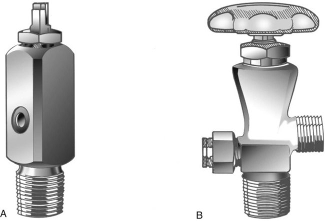
Cylinder Sizes and Contents
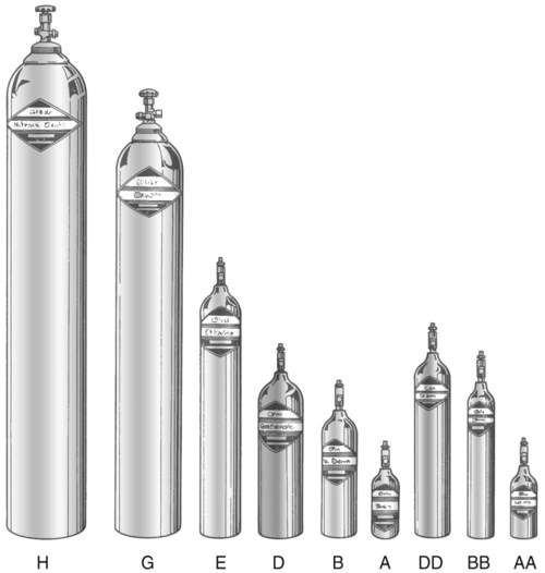
Letter designations are used for different sizes of cylinders (Figure 37-4). Sizes E through AA are referred to as “small cylinders” and are used most often for transporting patients and anesthetic gases. These small cylinders are easily identified because of their unique valves and connecting mechanisms. Small cylinders have a post valve and yoke connector. Large cylinders (F through H and K) have a threaded valve outlet (Figure 37-5) (discussed later).
Filling (Charging) Cylinders
Liquefied Gases
Gases with critical temperatures greater than room temperature can be stored as liquids at room temperature (see Chapter 6). These gases include CO2 and N2O. Rather than being filled to filling pressure, cylinders of these gases are filled according to a specified filling density. The filling density is the ratio between the weight of liquid gas put into the cylinder and the weight of water the cylinder could contain if full. The filling density for CO2 is 68%. This system allows the manufacturer to fill a cylinder with liquid CO2 up to 68% of the weight of water that a full cylinder could hold. The filling density of N2O is 55%.
Measuring Cylinder Contents
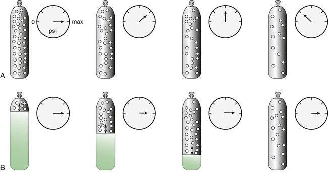
Liquid Gas Cylinders
Figure 37-6 compares the behavior of compressed gas and liquid gas cylinders during use. The vapor pressure of liquid gas cylinders varies with the temperature of the contents. The pressure in an N2O cylinder at 21.1° C (70° F) is 745 psig; at 15.6° C (60° F), the pressure decreases to 660 psig. As the temperature increases toward the critical point, more liquid vaporizes, and the cylinder pressure increases. If a cylinder of N2O warms to 36.4° C (97.5° F) (its critical temperature), all the contents convert to gas. Only at this temperature and higher does the cylinder gauge pressure accurately reflect cylinder contents.
Estimating Duration of Cylinder Gas Flow
< ?xml:namespace prefix = "mml" />

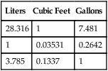
The units commonly used in the United States for measurement of these quantities are not the same. Cylinder contents are generally specified in cubic feet or gallons, whereas gas flow normally is measured in liters. Table 37-3 provides the factors needed to convert these units.
TABLE 37-3
| Liters | Cubic Feet | Gallons |
| 28.316 | 1 | 7.481 |
| 1 | 0.03531 | 0.2642 |
| 3.785 | 0.1337 | 1 |

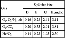
In the numerator of the previous equation, the English-metric conversion constant (28.3) is used to convert cubic feet to liters. Dividing the resulting volume by the pressure in a full cylinder yields the cylinder factor. The derived factor represents the volume of gas leaving a given cylinder for every 1-psig decrease in pressure. Table 37-4 provides cylinder factors for the therapeutic medical gases and common cylinder sizes.
TABLE 37-4
Factors for Calculation of Cylinder Duration of Flow (Minutes)
| Gas | Cylinder Size | |||
| D | E | G | H and K | |
| O2, O2/N2, air | 0.16 | 0.28 | 2.41 | 3.14 |
| O2/CO2 | 0.20 | 0.35 | 2.94 | 3.84 |
| He/O2 | 0.14 | 0.23 | 1.93 | 2.50 |

 Rule of Thumb
 Problem

Estimating Duration of Liquid Oxygen Cylinder Gas Flow


 Problem
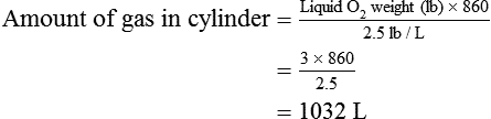
Gas Cylinder Safety
The following guidelines for cylinder safety are from the recommendations of the National Fire Protection Agency (NFPA)2 and the Compressed Gas Association (CGA).1 For ease of use, these safety guidelines are divided into cylinder storage, transport, and use.
Cylinder Storage
The following guidelines apply to cylinder storage:
• Store gas cylinders in racks or chain cylinders to the wall to prevent them from falling or becoming damaged.
• Other than the wooden racks used to store the cylinders, store no other combustible material in the vicinity of cylinders or gas supply systems.
• Store gas cylinders away from sources of heat. Keep the cylinder temperature less than 125° F (<51.7° C).
• Store flammable gases separately from gases that support combustion, such as air, O2, and N2O.
• If a cylinder is not in use, keep the protective cylinder cap in place.
• Do not store air compressors and gas cylinders together. A fire involving one or the other can damage both gas delivery systems.
• Contain and store cylinder supply systems in an enclosure constructed of a material with at least a 1-hour fire resistive rating that is well ventilated and well drained.
• Segregate full and empty cylinders; store them separately if possible.
• Place on each door or gate of the enclosure a sign that cautions the presence of an oxidizing gas and alerts against smoking. This sign must be readable from a distance of at least 5 ft (1.5 m).
• Store liquid O2 containers in a cool, well-ventilated area because of the venting of small amounts of O2 from these low-pressure containers. The venting of O2 prevents these containers from overpressurizing because liquid O2 is continuously converting to gaseous O2.
Cylinder Transport
The following guidelines apply to cylinder transport:
• Use cylinder carts with a securing mechanism for transportation of cylinders.
• Keep the protective cylinder caps in place during transportation of cylinders.
• Protect gas cylinders from striking other cylinders or objects to avoid damaging the safety devices, valve stems, or the cylinder itself.
• Avoid dropping, dragging, or rolling cylinders in transport.
• Do not transport cylinders for use that are not appropriately labeled.
Cylinder Use
The following guidelines apply to cylinder use:
• Secure gas cylinders at the patient’s bedside in a way that prevents them from falling. Secure cylinders to the wall with a chain, bind or chain them to a suitable cart, or support the cylinder with a stand.
• Do not use flammable materials, especially oil or grease, on regulators, cylinders, fittings, or valves. This restriction includes oily hands, rags, and gloves.
• Never cover a cylinder with any material, including bed linens or hospital gowns.
• Open the cylinder valve slightly to remove dust and dirt before attaching the regulator. When slightly opening the valve, ensure no one is in front of the valve. “Crack” the cylinder before bringing it to the patient’s bedside.
• Never use cylinder valves or regulators that need repair.
• Do not alter or deface cylinder markings or color.
• Never place cylinders near sources of heat.
• Never secure cylinders to movable objects unless the object has an apparatus that can contain the cylinder safely.
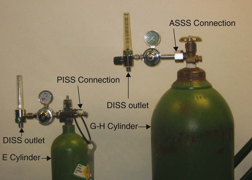
• Ensure that the connection between the regulator and the cylinder valve is an American standard safety system (ASSS) for H and G cylinders and a pin-index safety system (PISS) for E cylinders.
• When O2 is in use, post a “No Smoking” sign unless signs in the entrances are posted that prohibit smoking in the facility.
Bulk Oxygen
Large acute care facilities use large volumes of O2 every day. To meet these needs, a centralized bulk storage and delivery system is required. By definition, bulk O2 storage systems hold at least 20,000 cubic ft of gas, including the unconnected reserves that are on site.2 Bulk O2 may be stored in either gaseous or liquid form, but liquid storage is most common. When needed, the O2 flows from this central source throughout the facility through a piping system with outlets conveniently located.
Safety standards for bulk O2 systems are set by the NFPA and are subject to further control by local fire and building codes.2 RTs should be familiar with both bulk units in general and the specific gas supply systems used in their facilities.
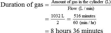
Gas Supply Systems
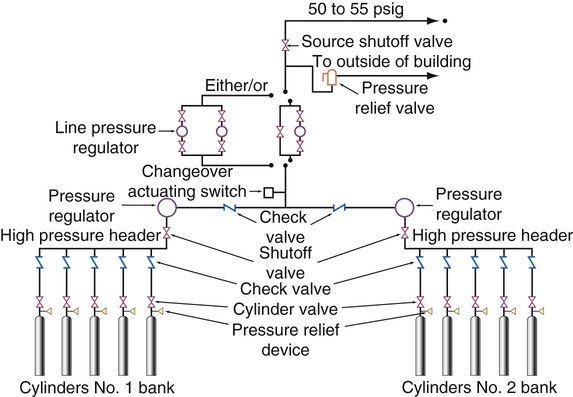
There are three types of centrally located gas supply systems: an alternating supply system or cylinder manifold system, a cylinder supply system with reserve supply, and a bulk gas system with a reserve.2 The alternating supply or cylinder manifold system consists of large (normally H or K size) cylinders of compressed O2 banked together in series (Figure 37-7). This alternating supply system has two sides: a primary bank and a reserve bank. When the pressure in the primary bank decreases to a set level, a control valve automatically switches over to the reserve bank. When this occurs, the primary bank is taken off-line, and the empty cylinders are replaced with full ones. The replenished primary bank becomes the reserve bank. Some large alternating supply systems are permanently fixed and are refilled on site by a supply truck. These cylinder manifold systems have pressure-reducing valves for regulation of delivered pressure and normally have low-pressure alarms. These alarms sound when reserve switchover occurs, and they warn of impending depletion or malfunction. Cylinder manifolds or alternating supply systems are used to supply O2 from a central location in small facilities or to supply specialty gases, such as N2O, to operating rooms (Figure 37-8).
A cylinder supply system with a reserve consists of a primary supply, a secondary supply, and a reserve supply. When the primary gas supply is depleted by the demand, this supply system automatically switches to the secondary supply. Master signal panels indicate that the changeover has occurred. This supply system operates in a manner similar to the alternating system except that this system has a reserve supply if primary and secondary supplies become depleted. Liquid containers may be used as the primary and secondary gas sources, but the reserve supply usually is high-pressure gas cylinders. Gas cylinders are used as the reserve supply because low-pressure liquid containers lose approximately 3% of the supply per day.2
For economy, safety, and convenience, most large health care facilities use a liquid bulk O2 system. A small volume of liquid O2 provides a very large amount of gaseous O2 and minimizes space requirements. However, along with this advantage comes a major problem. O2 has a critical temperature well below room temperature (−118.6° C [−181.4° F]).1 Liquid O2 must continually be stored below this temperature, or it reverts to its gaseous state.
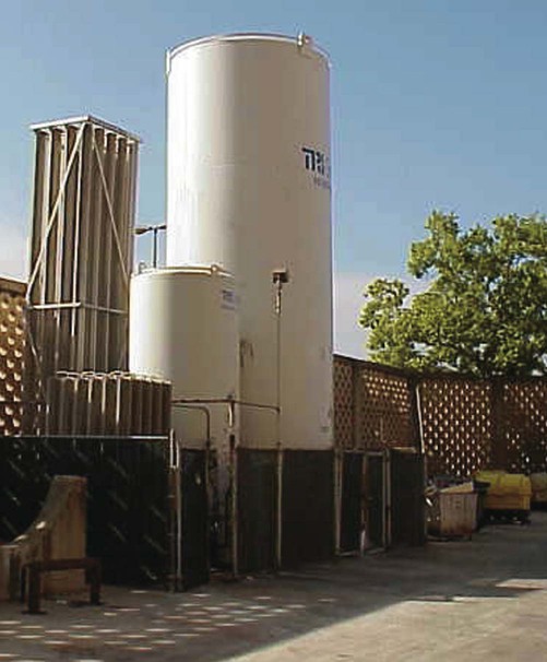
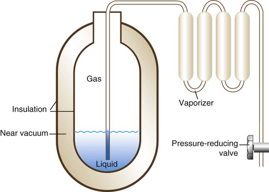
To stay in liquid form, O2 is stored in large stand tanks (Figure 37-9) at relatively low pressure (<250 psig). These stand tanks are similar to giant thermos bottles, consisting of inner and outer steel shells separated by an insulated vacuum chamber (Figure 37-10). Because it eliminates heat conduction, the vacuum keeps the liquid O2 below its critical temperature without refrigeration. When it flows through vaporizer coils exposed to ambient temperature, the liquid O2 quickly converts back to a gas. With the O2 in its gaseous form, the pressure is decreased to the standard working pressure of 50 psi by a pressure-reducing valve. A safety vent allows vaporized liquid O2 to escape if warming causes cylinder pressure to increase above a set limit.
Smaller liquid cylinders are used for home O2 supply. These cylinders come in several sizes and hold between  cubic ft and
  cubic ft of liquid O2. Small liquid O2 cylinders are refilled on site by means of transfer of liquid O2 from a large cylinder. Chapter 51 describes the use of these small liquid O2 cylinders in the home.
Bulk Oxygen Safety Precautions
The NFPA sets standards for the design, construction, placement, and use of bulk O2 systems.2 A key provision in these standards is the requirement for a reserve or backup gas supply to equal the average daily gas usage of the hospital. To meet this requirement, most large facilities have a second, smaller liquid stand tank. Smaller facilities may use a cylinder gas manifold as the backup.
Failure of bulk O2 supply systems has been reported with resultant major problems.13–15 Failure of a bulk O2 supply can be life-threatening to any patient receiving O2 or gas-powered ventilatory support. For this reason, the respiratory care staff must be prepared. Adherence to an established protocol is a quick way to identify and prioritize all affected patients. When affected patients are identified, staff members move appropriate backup equipment to the bedside (e.g., portable cylinders, bag-valve-mask resuscitators). Trained personnel bypass the failed system and provide needed patient support, while engineers determine the cause of the failure and correct it.
Distribution and Regulation of Medical Gases
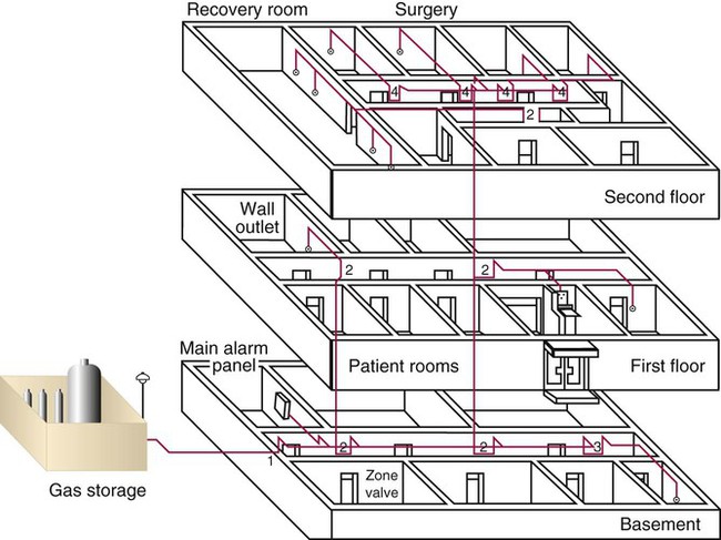
Central Piping Systems
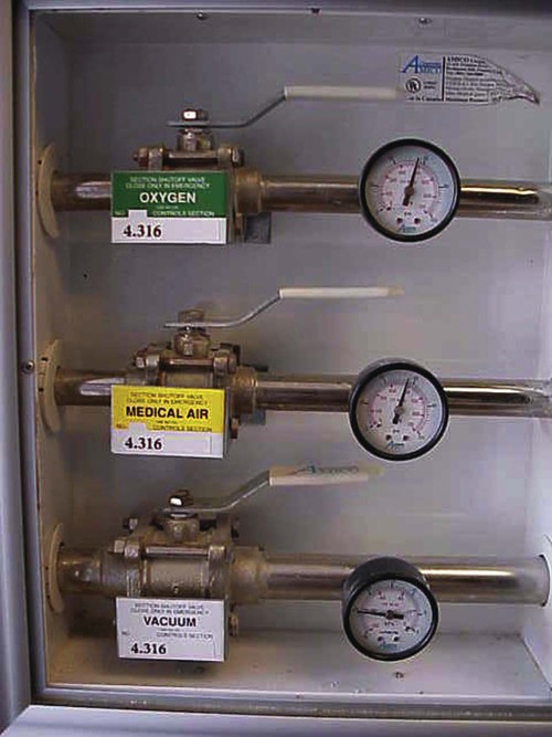
Structural standards for piping systems are established by the NFPA and are described in more detail elsewhere.2 Figure 37-11 shows a simple central piping gas system. The gas pressure in a central piping system normally is reduced to the standard working pressure of 50 psi at the bulk storage location. A main alarm warns of decreases in pressure or interruptions in flow from the source. Zone valves (Figure 37-12) throughout the system can be closed for system maintenance or in case of fire. Wall or station outlets at the delivery sites allow connection of various types of equipment to the gas distribution system. Because most delivery outlets include O2, air, vacuum, and possibly N2O, special safety connectors are used to help prevent accidental misconnections.
Safety Indexed Connector Systems
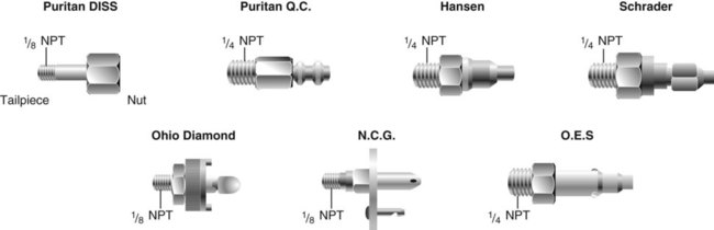
One of the greatest risks in medical gas therapy is giving the wrong gas to a patient. Carefully reading the cylinder or outlet labels is the best way to avoid these accidents. However, human error does occur. For this reason, the industry has developed indexed safety systems for gas delivery and regulation equipment. These safety systems make misconnection between pieces of equipment nearly impossible. For example, an indexed safety system normally prevents connecting a cylinder of N2O to an O2 delivery system. Three basic indexed safety systems are used in the delivery and regulation of medical gases: (1) the American National Standard/Compressed Gas Association Standard for Compressed Gas Cylinder Valve Outlet and Inlet Connections, or the ASSS; (2) the diameter-index safety system (DISS); and (3) the PISS.16,17
American Standard Safety System
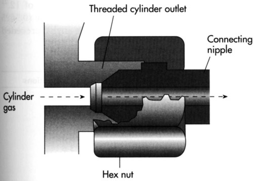
Adopted in the United States and Canada, the ASSS provides standards for threaded high-pressure connections between large compressed gas cylinders (sizes F through H/K) and their attachments.16 Specifications exist for more than 60 gases and gas mixtures. Figure 37-13 shows a typical ASSS connection between a threaded cylinder outlet and a pressure-reducing valve nipple. Use of the ASSS standards makes misconnections difficult because the size (bore) of the cylinder outlet and its threading differ based on the type of gas in the cylinder.
Pin-Index Safety System
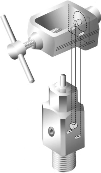
Pin indexing is part of the ASSS but applies only to the valve outlets of small cylinders, up to and including size E. These cylinders have a yoke type of connection. Figure 37-14 illustrates the general structure of the pin-indexed yoke connection. The upper yoke fits over the lower valve stem. Two pins, projecting from the inner surface of the yoke connector, mate with two pinholes bored into the valve stem. Proper pin position aligns the small receiving nipple of the yoke with the recessed cylinder valve outlet. Tightening the hand screw on the yoke firmly seats the receiving nipple into the valve outlet. A nylon washer or bushing typically is used to ensure a leak-free connection.
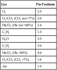
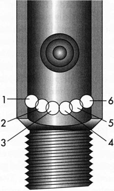
Similar to the ASSS, the PISS helps prevent accidental misconnections between pieces of equipment. The exact positions of pins and pinholes vary for each gas. Unless the pins and holes align perfectly, the yoke nipple cannot seat in the recessed valve outlet. Six holes and pin positions constitute the total system. Because overlapping holes cannot be used, there are 10 possible pin combinations. Figure 37-15 is a diagram of the location of all six possible holes and their index numbers. Table 37-5 lists the gases included in the PISS system, including their index positions.
TABLE 37-5
| Gas | Pin Positions |
| O2 | 2-5 |
| O2/CO2 (CO2 not >7%) | 2-6 |
| He/O2 (He not >80%) | 2-4 |
| C2H4 | 1-3 |
| N2O | 3-5 |
| C3H6 | 3-6 |
| He/O2 (He >80%) | 4-6 |
| O2/CO2 (CO2 >7%) | 1-6 |
| Air | 1-5 |
Diameter-Index Safety System
The ASSS and the PISS provide standards for high-pressure connections between cylinders and equipment; the DISS was established to prevent accidental interchange of low-pressure (<200 psig) medical gas connectors.17 RTs typically find DISS connections (1) at the outlets of pressure-reducing valves attached to cylinders; (2) at the station outlets of central piping systems; and (3) at the inlets of blenders, flowmeters, ventilators, and other pneumatic equipment.
As shown in Figure 37-16, the DISS connection consists of an externally threaded body and a mated nipple with a nut. As the two parts are joined, the shoulders of the nipple and the bores of the body mate, with the union held together by a hand-tightened hex nut. Indexing is achieved by varying the dimensions of the borings and shoulders. There are 11 indexed DISS connections and 1 connection for O2, for a total of 12.17 The standard threaded O2 connector (0.5625 inch in diameter and 18 threads per inch) preceded adoption of this safety system. Nonetheless, it has been assigned a DISS number of 1240.
Although O2 and air are generally used from a central outlet, it may be necessary to administer other gases that have different DISS connections. To avoid stocking a large variety of pressure regulators, flowmeters, and connectors for special gas use, adapters can be used to convert various DISS connections so that they can be used for different purposes. Using adapters to bypass a safety system carries the increased risk of misconnection. For this reason, RTs should exercise extreme caution when adapting equipment connections. Misconnections have occurred, with negative patient consequences.13,18
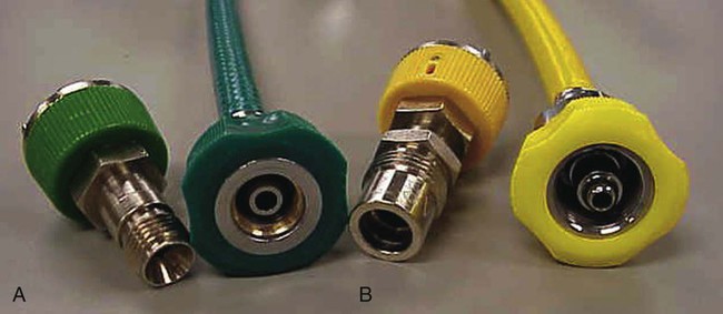
Quick-Connect Systems
Station outlets at the patient’s bedside allow quick access to a bulk supply of O2 and air or a vacuum source. Station outlets have DISS connections or quick-connect systems that are gas-specific or vacuum-specific. Various manufacturers have designed specially shaped connectors for each gas (Figure 37-17). Because each connector has a distinct shape, it does not fit into an outlet for another gas, and each manufacturer has its own unique design. For this reason, connectors from different manufacturers are not interchangeable. As long as a facility is standardized for a single quick-connect system, this incompatibility is seldom a problem.
A variety of safety systems help prevent inadvertent misconnections between medical delivery systems and equipment. Figure 37-18 summarizes the use of and relationships between the ASSS, PISS, and DISS systems as applied to cylinder gases. Proficiency in the proper use of these systems is a basic skill of RTs.
Regulating Gas Pressure and Flow
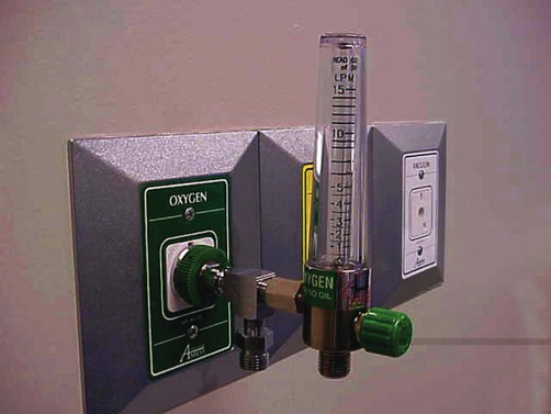
Cylinder gases such as O2 and air exert a pressure that is much too high for use with respiratory care equipment. For use at the bedside, these high pressures must be reduced to a lower “working” level. In the United States, this working pressure is 50 psig. For bulk delivery systems with individual station outlets, built-in reducing valves decrease the delivered pressure to 50 psig. This standard pressure can be directly applied to power devices such as ventilators (see Chapter 42). However, if the goal is to control gas delivery to a patient for O2 therapy or nebulized medication (see Chapters 36 and 38), a flowmeter must also be used.
High-Pressure Reducing Valves
Preset Reducing Valve
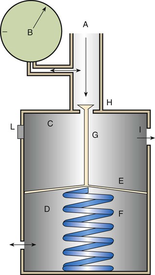
Figure 37-19 shows the basic design of a high-pressure preset reducing valve. High-pressure gas (2200 psig for O2) enters through the valve (A), with the inlet pressure displayed on the pressure gauge (B). The body of the valve is divided into a high-pressure chamber (C) and an ambient-pressure chamber (D) by a flexible diaphragm (E). Attached to the diaphragm in the ambient-pressure chamber is a spring (F), which is fixed to the other side of the chamber. Also attached to the diaphragm, but in the high-pressure chamber, is a valve stem (G) that sits on the high-pressure inlet (H). Gas flows through the valve inlet (H) into the high-pressure chamber and on to the gas outlet (I). The pressure chamber is supplied with a safety vent (L) preset to 200 psig to release pressure in the event of malfunction.
Adjustable Reducing Valve
Although most respiratory care equipment works at the standard 50 psig, some devices need variable pressures. To provide variable outlet pressures from a high-pressure gas source, an adjustable reducing valve is needed. Figure 37-20 shows the basic design of a high-pressure adjustable reducing valve. As with the preset design, the inlet valve (H) remains open until the gas pressure exceeds the spring tension, displacing the diaphragm and blocking further gas entry. However, while the preset reducing valve provides a fixed pressure, the adjustable reducing valve allows a change in outlet pressure. Outlet pressure can be changed with a threaded hand control (K) attached to the end of the diaphragm spring. Changing the tension on the valve spring varies pressure over a wide range, usually between 0 psig and 100 psig.
Proper Use of High-Pressure Reducing Valves
When a cylinder attached to a high-pressure reducing valve is open, gas undergoes rapid decompression followed by rapid recompression. Because the recompression is adiabatic (see Chapter 6), the gas temperature quickly increases. These rapid pressure and temperature changes are potentially hazardous. Rapid pressure swings can cause failure of reducing valve components.19 Failed components can become high-velocity projectiles, endangering the practitioner and the patient. Rapid temperature changes can ignite combustible materials.20 Ignition of combustible materials in the presence of 100% O2 can cause an explosion. Box 37-1 provides guidelines for minimizing the risk associated with setting up O2 cylinders with a high-pressure reducing valve or regulator.1
 Problem
Low-Pressure Gas Flowmeters
Flow Restrictor
The flow restrictor is the simplest and least expensive flowmeter device. As shown in Figure 37-21, a flow restrictor consists solely of a fixed orifice calibrated to deliver a specific flow at a constant pressure (50 psig). The operation of the flow restrictor is based on the principle of flow resistance, as described in Chapter 6. Specifically, the flow of gas through a tube can be quantified with the following equation:
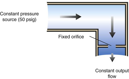

Rearranging the equation to solve for flow (V) yields the following:

By design, a flow restrictor requires a source of constant pressure (usually 50 psig). As long as the source pressure remains fixed, P1 − P2 should stay constant. With a fixed-size orifice, the flow resistance (R) also remains constant. The rate of gas flow through a flow restrictor can be increased by increasing P1 (upstream pressure) or by selecting a larger orifice size. Both fixed and adjustable orifice flow restrictors are used clinically. Commercially produced flow restrictors are calibrated at 50 psig. Table 37-6 summarizes the advantages and disadvantages of flow restrictors.
TABLE 37-6
Advantages and Disadvantages of Flow Restrictors
| Advantages | Disadvantages |
| Low-cost, simple, reliable (no moving parts) | Different versions required for different flows |
| Cannot be set to incorrect flow | Accuracy varies with changes in source and downstream pressures |
| Can be used in any position (gravity-independent) | Cannot be used with high-resistance equipment |
Bourdon Gauge
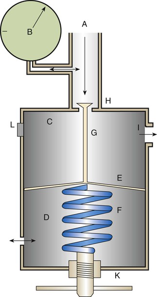
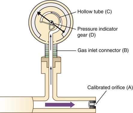
A Bourdon gauge (Figure 37-22) is a flowmeter device that is always used in combination with an adjustable pressure-reducing valve. Similar to the flow restrictor, the Bourdon gauge uses a fixed orifice. In contrast to the flow restrictor, the Bourdon gauge operates under variable pressures, as adjusted with the pressure-reducing valve. The Bourdon gauge is a fixed-orifice, variable-pressure flowmeter, so increasing the upstream pressure increases gas flow out of the device unless downstream pressure also increases.
As shown in Figure 37-23, a Bourdon gauge has a calibrated fixed orifice (A), which creates outflow resistance. The gauge itself is attached to the flow stream with a connector (B) located proximal to the orifice. Inside the gauge is a curved, hollow, closed tube (C) that responds to pressure changes by changing shape. The force of gas pressure tends to straighten the tube, causing its distal end to move. This motion is transmitted to a gear assembly and indicator needle (D). A numbered scale is calibrated to read the needle movement in units of flow (liters per minute).
The main disadvantage of the Bourdon gauge is its inaccuracy when pressure distal to the orifice (downstream pressures) changes. Specifically, if downstream pressure increases (as when high-resistance equipment is used), the pressure difference across the orifice and actual output flow decrease. However, the Bourdon gauge flow reading depends on upstream pressure, which stays constant. In this situation, the gauge reading is falsely higher than the actual delivered flow. Because it measures upstream pressure, the gauge registers flow even when the outlet is completely blocked (Figure 37-24). A user who needs accurate flow when using a device that creates high resistance should not select a Bourdon gauge. A compensated Thorpe tube should be used instead.
Integrated O2 cylinders (Figure 37-25), including the Grab ’n Go System (Praxair, Inc, Danbury, Connecticut), have combined the O2 cylinder with a pressure regulator and an adjustable flow restrictor to meter O2 flow. These portable O2 systems eliminate the need for separate O2 tanks, Bourdon gauge regulators, and O2 keys or wrenchs (needed to turn on standard E-cylinders). These integrated systems virtually eliminate problems and delays associated with incorrectly mounted regulators. The practitioner simply selects the flow on the flow-adjusting knob and connects the O2 tubing to the system connection and the patient.
Thorpe Tube
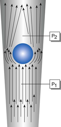
The Thorpe tube flowmeter (Figure 37-26) is always attached to a 50-psig source, either a preset pressure-reducing valve or a bedside station outlet. Compared with the flow restrictor and the Bourdon gauge, the Thorpe tube functions as a variable-orifice, constant-pressure flowmeter, so increasing the size of the orifice increases the gas flow. Figure 37-27 shows how a Thorpe tube works. The key component in this device is a tapered transparent tube that contains a float. The diameter of the tube increases from bottom to top. Gas flow suspends the float against the force of gravity. To read the flow, one simply compares the float position with an adjacent calibrated scale, normally calibrated in liters per minute.
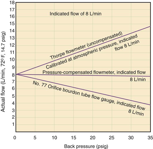
The uncompensated Thorpe tube flowmeter is calibrated in liters per minute but at atmospheric pressure (without restriction). Gas from a 50-psig source flows into the meter at a rate controlled by a needle valve located before the flow tube (Figure 37-28, A). When the user attaches flow-restricting equipment to the meter, downstream resistance increases, increasing pressure in the flow tube. As long as this pressure does not exceed 50 psig, gas continues to flow through the tube. However, the added downstream resistance increases the pressure in the flow tube above atmospheric pressure. At higher pressures, a greater amount of gas flows through a given restriction than at atmospheric pressure. With the float at a given height, more gas flows through the tube than is indicated on the scale. Under these conditions, an uncompensated Thorpe tube falsely shows a flow lower than that actually delivered to the patient.4
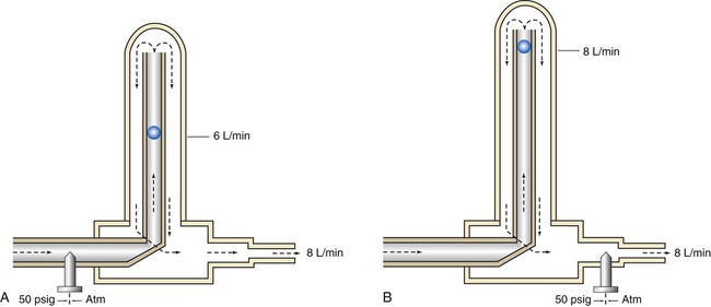
In contrast, the scale of the compensated Thorpe tube flowmeter is calibrated at 50 psig instead of at atmospheric pressure. Its flow control needle valve is placed after (distal to) the flow tube (see Figure 37-28, B). The entire meter operates at constant 50-psig pressure. Knowing that the compensated Thorpe tube operates at 50 psig helps identify it. When a compensated Thorpe tube is connected to a 50-psig gas source with the needle valve closed, the float “jumps” and then returns to zero as the Thorpe tube is pressurized. Because the entire meter operates at constant pressure, an increase in downstream resistance increases pressure distal to the needle valve only. As long as the downstream pressure does not exceed 50 psig (in which case flow ceases), the position of the float accurately reflects actual outlet flow. For this reason, the pressure-compensated Thorpe tube is the preferred instrument in most clinical situations.
The only factor limiting the use of a pressure-compensated Thorpe tube is gravity. Because it is accurate only in an upright position, a Thorpe tube is not the ideal choice for patient transport. In these cases, the gravity-independent Bourdon gauge is a satisfactory alternative. Figure 37-29 summarizes the effects of downstream resistance, or back pressure, on the Bourdon gauge and pressure-compensated and uncompensated Thorpe tube flow metering devices.
Mini Clini
Selection of Devices to Regulate Gas Pressure or Control Flow
 Problem
1. Because he has to transport a patient using O2, Mark should select an E cylinder with an adjustable regulator that includes a Bourdon gauge (unaffected by gravity) or an integrated O2 cylinder that includes an adjustable flow restrictor.
2. Because pneumatically powered ventilators require 50 psig and no central outlets are available, Carmen needs a preset (50 psig) reducing valve and a large G/H O2 cylinder.
3. Because all modern ICUs have central wall outlets for O2, Monica need only select a flowmeter with the appropriate quick connect. A compensated Thorpe tube is required for metering flow through high-resistance equipment such as jet nebulizers.