41 Spinal Cord Stimulation and Implanted Intrathecal Drug Infusion
Spinal Cord Stimulation
The use of electricity to mitigate the experience of pain is long and varied in human history. After Melzack and Wall’s 1965 publication in Science,1, in which they proposed the gate control theory of pain reduction, there appears to have been renewed interest in electricity as an adjunct in pain management. Transcutaneous nerve and muscle stimulation has enjoyed a long history of use.2 The effectiveness of these devices for managing chronic pain is debated.3,4
Spinal cord stimulation as a modern pain management practice was introduced by Shealy and colleagues in 1967.5,6 Shealy reported reduced pain in a patient by placing electrodes in the intrathecal space adjacent to the dorsal column of the spinal cord. Various mechanisms of spinal cord stimulation have been proposed and remain an area of ongoing research. Likely, multiple mechanisms play a role.7,8–15
Current spinal cord stimulator systems consist of an epidural array of contacts and a power source or “pulse generator”. Typically patients are afforded a trial period during which the pulse generator is an external device connected to percutaneously inserted epidural electrodes. When the system is permanently implanted, the power source is surgically implanted into a subcutaneous pocket and is called an implanted pulse generator (IPG). Various stimulating parameters are adjustable on both external and internal power sources and represent the “programming” aspect of spinal cord stimulator management. For both trial and permanent implantation, electrode arrays are implanted into the epidural space as either “catheter-” or “paddle”-shaped devices. The catheter-shaped electrode or “percutaneous lead” is inserted through a specially configured needle-type introducer. The introducer is advanced into the epidural space utilizing fluoroscopic guidance and typically with a loss of resistance technique. The introducer may be inserted through the skin (percutaneous) or placed after an incision is made. One or more percutaneous leads are implanted to create the epidural array of metal electrode contacts. “Paddle” electrodes or laminotomy leads are much larger plastic substrate devices to which multiple metal electrode contacts are attached in various configurations. Figures 41-1 and 41-2 are images of current Medtronic and St. Jude Medical (Advanced Neuromodulation Systems, Inc. [ANS]) percutaneous and laminotomy leads. Because of their size, paddle electrodes require laminotomy or laminectomy for placement. Early electrode arrays were 2 or 4 contacts and available power sources contained only non-rechargeable batteries or required an inductive coil held over an implanted receiver coil for continuous power. At this writing, implanted power sources are capable of connecting up to 16 contacts and contain rechargeable or non-rechargeable batteries. Figures 41-3 and 41-4 are images of Medtronic and St. Jude Medical (ANS) implanted pulse generators.
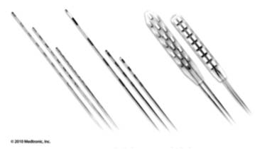
Figure 41-1 Medtronic percutaneous and laminotomy leads.
(Reprinted with the permission of Medtronic, Inc. ©2010.)
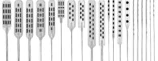
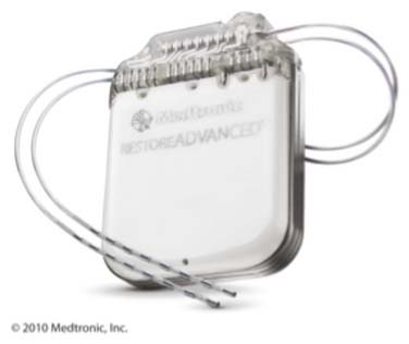
Figure 41-3 Medtronic rechargeable IPG with percutaneous leads connected.
(Reprinted with the permission of Medtronic, Inc. ©2010.)
Electrode arrays are most commonly placed in the epidural space between the second cervical and the eleventh thoracic vertebra levels over the middle portion of the cord. Retrograde electrode placement to stimulate sacral and lower lumbar nerve roots, lateral lead placement to stimulate nerve roots within the spinal canal, peripheral nerve stimulation, and subcutaneous “field” stimulation16 are all areas of ongoing investigation.17,18 This discussion is limited to traditional “dorsal column” stimulation, which represents the most common current usage of the SCS equipment.
Indications
Appropriate patients for SCS would include those whose pain is not acceptably managed with less invasive therapies and those for whom a definitive surgical procedure is not offered or is not desired.19 Often reserved for use later in a pain management continuum, spinal cord stimulation may be offered early in some cases, especially in the management of predominantly neuropathic and complex regional pain. Spinal cord stimulation has FDA indications in the management of pain of the trunk and or limbs. This somewhat nonspecific indication reflects the broad array of painful conditions that have been helped using spinal cord stimulation. Good to excellent long-term pain relief has been obtained in multiple chronic pain syndromes including failed back surgery syndrome (FBSS),20–28 complex regional pain syndrome (CRPS),29–37 postherpetic neuralgia,38–42 and radicular pain secondary to central and foraminal stenosis in the nonoperated patient.
Several other painful conditions have been successfully managed with SCS including: pain secondary to inoperable ischemic cardiac pain,43–54 diabetic peripheral neuropathy,55,56 peripheral vascular ischemic pain, and Raynaud syndrome.57,58 Thoracic, abdominal and pelvic pain coverage with SCS has enjoyed only limited success but clinical efforts continue to afford SCS benefits to these patients.59–62 Early in its history, but rarely today, SCS has been used for spasticity management.63–68
Contraindications
The following situations would generally contraindicate SCS:
Equipment
The basis for all SCS systems is essentially the same: Various forms of a low voltage alternating current are passed from the generator to an array of electrode contacts in the epidural space to generate an electric field within the spinal cord.72–75 This electric field affects a change in the central nervous system and, when effective, the experience of pain. Each company has claims to unique benefits, programmability, battery life, stimulation parameters, constant voltage versus constant current and various equipment features. Implanter experience with the various products, individual bias, possibly geographic location due to product support issues, and experience of the manufacturers support personnel are important when choosing which company or companies to choose.
Preoperative Considerations
Preoperative evaluation and preparation of a patient are critical to optimizing outcomes. Most implanters and payers will require a pre-implant psychological evaluation.76–78 This evaluation is best accomplished by a licensed psychologist or psychiatrist who has a clear understanding of issues associated with chronic severe pain and spinal cord stimulation. This evaluation helps the implanting physician identify psychological factors that invariably are present in patients with chronic severe pain. Occasionally, psychological issues are identified that require treatment prior to further consideration of spinal cord stimulator therapy. Good collaboration between the psychologist or psychiatrist and implanting physician is important and that all involved understand and address psychological issues. Long-term psychological needs may also be identified during this evaluation. Mostly the evaluation is an attempt to identify psychological issues that would preclude a patient from being considered for implantation. It is important that this evaluation be obtained before placement of the trial and incorporated in the overall pre-implant decision-making process.
An accurate and timely history and physical examination appropriate for a surgical patient is reasonable. This would include past surgeries, surgical complications, bleeding problems, drug allergies, current medications—with specific attention to those affecting coagulation,79,80 and appropriate review of systems. A physical examination related to the proposed procedure would include a focused neurologic examination, auscultation of the heart and lungs, abdominal palpation, and inspection of the proposed surgical sites for evidence of infection. A discussion with the patient and significant others regarding external wires and the trial pulse generator for a trial placement, expected incision locations for permanent implant, expected increased pain, and activity restrictions is prudent. Preoperative laboratory testing may be appropriate to rule out infections, bleeding problems, and chemical abnormalities. Chest radiographs and ECG may also be appropriate in patients with significant cardiac or pulmonary history. Specific tests and studies obtained are determined by individual patient considerations, facility requirements, and anesthesia needs.
Identification of possible immune deficiencies and, when indicated, evaluation of the immune status of patients is important. Patients with a history of recurrent infections, especially those known to have antibiotic-resistant organisms, are at particular risk. Diabetics, patients with poor personal hygiene, unsanitary living conditions, chronic renal failure, long-term steroid exposure, the elderly and/or debilitated, and most obviously, those with known immunoglobulin deficiencies require careful considerations. When in doubt, consulting an internist and/or infectious disease specialist is appropriate. Maximize immune function in those patients identified to be at risk when possible. Appropriate perioperative antibiotics in the at risk patient and possibly all patients are important in reducing operative infections. Most preoperative antibiotics are best given within 30 minutes prior to incision.
Trial Process Considerations
Long-term success of spinal cord stimulation cannot be completely predicted by the trial process. Positive placebo response with a trial implant can lead to poor permanent implant results. A positive placebo benefit will lessen over time and may account for many early nonimplant-related failures that appeared to have initially functioned well. If the trial protocol requires a very high reported level of benefit before a permanent implant is offered, improved long-term success would generally be expected. For example, patients who report only a 40% reduction in pain may be experiencing significant placebo response, and may not be the best candidates for permanent implantation. Factors to consider in the determination as to the effectiveness of the trial would include reported effects such as increase in activities of daily living; reduction in oral pain medication usage; family members reporting improvement in activities and mood; improved sleep pattern; and a reported decrease in level of pain during activities and at rest.
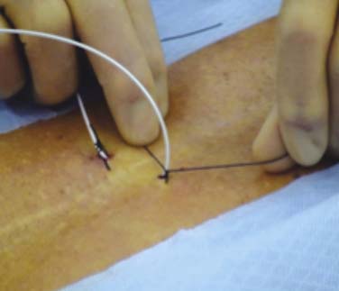
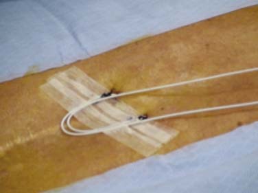
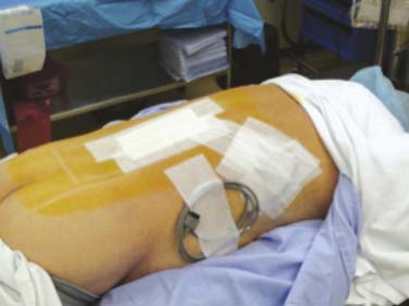
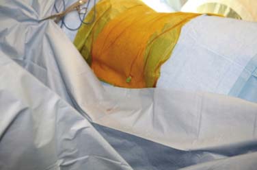
Percutaneous trial leads are placed through needle type introducers inserted through the skin. Lead location is adjusted based on the patient’s reported paresthesia when the lead is connected to a trial generator. The trial leads may be secured using various techniques. Figures 41-5, 41-6, and 41-7 demonstrate one method whereby the leads are sutured to the skin with 0-silk, tincture of benzoin applied and Steri-Strips are placed to create a loop of lead to act as a strain relief. A 4 × 4 dressing is applied and secured with wide 3M Medipore H tape. The trialing cable is also secured with tape to reduce stress at the lead cable connection.
After completion of the trial, the patient and care givers are questioned regarding perceived benefits, and if a pain diary was kept, it is reviewed. The percutaneous trial leads are most generally removed by gentle traction on the lead with the patient in a slightly flexed sitting position. If unusually severe or radicular pain is experienced when attempting removal, the patient is repositioned prior to further attempts.
Percutaneous Lead Placement
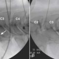
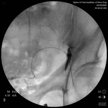
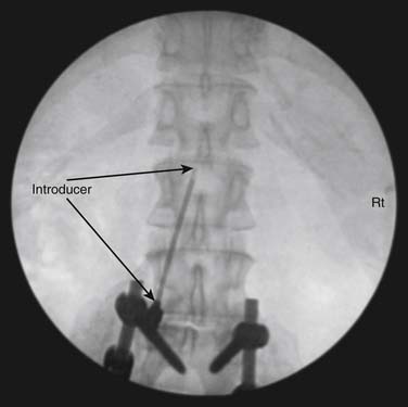
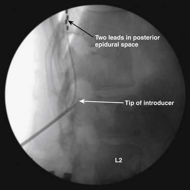
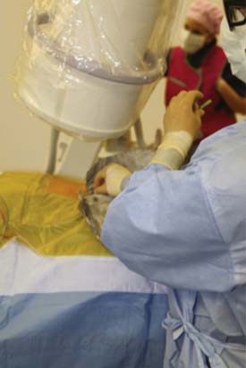
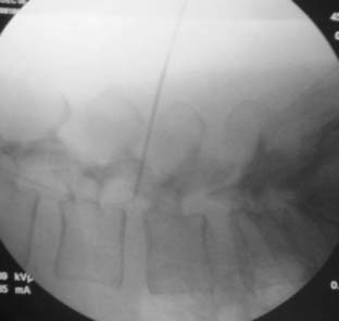
The spinal area being considered for placement of the introducer needle is imaged most generally with C-arm fluoroscopy. The C-arm is adjusted in oblique and tilted projections to provide an optimal view of the intended entry interspace. Inspection of the interspace may reveal boney changes that could make introducer placement or subsequent lead advancement difficult. Often, declining the fluoro beam to more closely match the needle entry angle can demonstrate obstruction or anatomic variations. Paramedian insertion of the introducer needle is preferred starting approximately one spinal level below. The entry angle of the introducer relative to the spine should be approximately 45 degrees when practical to allow for the lead to optimally emerge from the tip. This angle also improves the ability to “steer” or to control the lead tip as it is advanced. The introducer tip target is slightly ipsilateral and below the spinous process. Figure 41-8 shows a left paramedian introducer placement at T12-L1. Air or saline loss of resistance technique is most often used along with anterior-posterior and lateral fluoroscopy imaging as the needle is advanced to assist in identifying the epidural space. Nonionic contrast may also be employed if needed to help confirm epidural space placement.
Most introducer placements are at spinal levels where the spinal cord is present. Great care is exercised to have exacting needle control as the introducer is advanced so as not to cause damage to the spinal cord. Figure 41-9 demonstrates one technique of holding the syringe and needle. Notice the operator’s left thumb and index fingers grasping the needle at the skin level while the right hand gently “bounces” the syringe plunger providing pressure for the loss of resistance. The introducer is advanced only by the fingers pinching the needle while the right hand assists in directing the introducer. Using this technique, the introducer is less likely to be accidentally advanced into the dural space possibly causing spinal cord or nerve root injury.
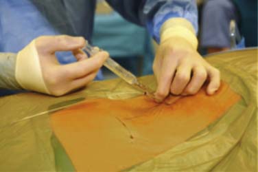
Figure 41-9 Exact needle control during introducer placement. Advancing only with the left thumb and index finger.
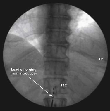
Once the introducer is in place, an electrode or lead is inserted through it and advanced staying midline or slightly off midline to a level above the expected final implant level. When practical, it is best that the electrode emerge from the introducer directly cephalad and not angled to either side. Fig. 41-10 demonstrates the lead emerging from the introducer directed cephalad. Lumbar and thoracic leads can easily stray laterally when advanced and pass laterally and then into the anterior epidural space where paresthesia is not pleasant. Depending on implanter experience and the desired paresthesia, the lead may be placed directly midline or slightly off midline.
If on initial trialing, the patient reports a sharp biting pain at a very low power setting, the lead may be intrathecal. The lead is withdrawn and an attempt may be made to reinsert at this or a different level. On occasion, CSF in the epidural space from a dural puncture by the introducer may make trialing the lead difficult because the CSF interferes with the conductance. In this situation, the procedure is best abandoned and again tried at a later date. If the lead is being placed in the thoracic region, and the patient reports sharp pain within the chest wall or abdomen, the lead may be in the anterior epidural space or lateral in the posterior epidural space stimulating the nerve roots. A lateral fluoroscopic image is often useful in diagnosing these placements. Stimulation of the ligamentum flavum may be reported as a sharp or biting posterior sensation as the power is increased.81 Repositioning of the lead may reduce this undesired stimulation. Implantation of laminotomy leads in lieu of percutaneous leads is thought to reduce this ligamentum stimulation.
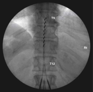
Many implanters repeat this lead implantation process with additional leads to provide optimal paresthesia coverage and afford more programming flexibility.82 With changes in pain patterns, electrode movement, and scar formation, reprogramming with multiple contacts is generally more successful. Two percutaneous leads are generally placed in this fashion to provide an electric field across the spinal cord. Occasionally, three electrodes are implanted and are thought to possibly offer some advantage from a “tri-pole” electrical field.83 Fig. 41-11 is an AP radiograph showing the electrode positions following trialing but before the introducers were removed and Figure 41-12 shows a lateral projection of the same leads after one introducer was removed.
Surgical Implantation of Percutaneously Placed Leads
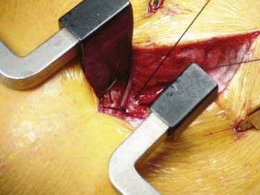
Lead movement from the initial implant location is the most common cause of lead failure. This typically arises from failure at the anchor. Leads can move laterally or medially without failure at the anchor site. Device companies have made good progress in developing new anchors that securely hold the lead with minimal circumferential pressure. Proper use of anchors, referencing manufacturer technique recommendations, and suturing to appropriate structures are critical to long- and short-term success. The anchor is generally sutured along the posterior lateral aspect of the spine, such that the leads are not sharply bent. This reduces stress points that can cause failure of the internal wires. Anchors are applied as close as practical to the point where the lead enters the interspinal ligament or fascia. Figure 41-13 shows an anchor sutured at each end and a tie being passed around the anchor to apply circumferential pressure securing the lead to the anchor. Leads may pull back with spinal flexion-extension movement and emerge between the fascia entry point and the anchor, especially if this distance is great. A nonabsorbable, purse-string suture placed around the introducer needle prior to removal and tightened after final verification of lead position may reduce this complication.
Permanent Laminotomy Lead Implantation
Laminotomy or surgical leads are also referred to as paddle leads because of their shape. A laminotomy or laminectomy is generally required to provide enough room for insertion into the epidural space. Electrode contacts reside on the surface toward the spine and are, therefore, insulated on the posterior surface. Generated electric fields with these leads are unidirectional toward the dura and spinal cord. The posterior surface against the ligamentum flavum is insulated, so stimulation of the ligament is unlikely. These leads tend to be more efficient and require less power to produce paresthesia. Current laminotomy leads have 4 to 16 contacts arranged in various configurations of contact size, spacing, and orientation. It is likely that their larger size makes them less prone to movement when implanted.
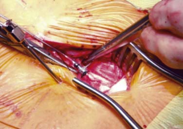
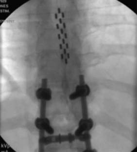
The placement of paddle electrodes may be accomplished using minimally invasive spinal retractors and access systems or via a traditional open laminotomy.84 Figure 41-14 shows a laminotomy lead being implanted using a minimally invasive technique. To confirm useful concordant paresthesia, the patient is questioned during trial stimulation whenever a lead array is being implanted. Intraoperative questioning requires the laminotomy be performed using spinal or epidural block and local anesthesia infiltration with sedation when required.85 Spinal and epidural block anesthesia along with local anesthesia infiltration can be used when correct paresthesia reported.86 The location of optimal laminotomy lead placement can often be well approximated by a previously performed percutaneous trial. When the laminotomy lead is placed under general anesthesia at the level as determined by the trial, a risk is taken that, upon patient awakening, less than optimal coverage will be afforded. Figure 41-15 shows a tripole laminotomy lead implanted slightly right of midline.
Radiation Safety
Considerable radiation exposure may be had by the implanting physician during introducer placement and lead manipulation. This is especially true during the early phases of learning. Techniques used to reduce radiation exposure include using a modern C-arm fluoroscopy machine in the pulse and low-dose modes when appropriate; using collimation to view only those areas needed to be imaged; using AP imaging with the x-ray source under the patient; keeping hands out of the x-ray beam; positioning the image so that the area of interest is at the bottom of the image screen; lowering the image intensifier as practical; and proper lead shielding of the surgeon. Proper lead shielding includes leaded goggles to protect the eyes; thyroid shield; full lead apron; and lead batons hanging from the side of the table. A piece of lead sheeting may be fashioned to provide an area of minimal radiation to protect the hands. This shield is sterilized and laid over the drapes. All these maneuvers play a role in reducing lifetime radiation exposure. With practice and experience, typically radiation exposure becomes much less. Figure 41-16 shows fluoroscopy positioning, lead apron, thyroid shield, lead eye protection, and the use of a sheet of lead to protect the hands. Some of these efforts will also reduce radiation exposure to the patient.
Pocket Creation and IPG Implantation
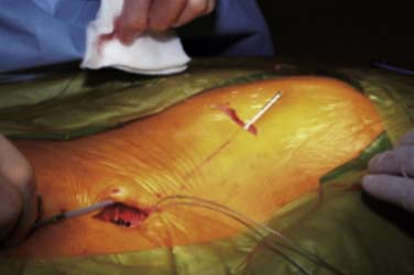
After placement of the epidural lead array, a subcutaneous area or pocket is created to accommodate an IPG. Following infiltration of the proposed pocket area with local anesthetic containing epinephrine to reduce bleeding, a horizontal incision is made to the subcutaneous fat layer. Blunt finger dissection and electrocautery is used inferior to the incision to develop a pocket. Pockets are most often developed in the upper buttocks just lateral to the upper sacrum. This area typically is below the belt line and pressure against a chair is minimal. Smaller power sources may allow for a suitable pocket to be developed adjacent to the lead implant spinal incision. Recharging may be more difficult with the IPG in these areas and should be considered when planning pocket location. Other IPG pocket sites include the abdomen or infraaxillary region. Placement under muscle or a fascial layer may be needed in extremely thin patients.
A tunneling device is inserted through the subcutaneous tissues and passed between the pocket and the spine incision. The leads or lead extensions when required are passed or drawn into the pocket. Figure 41-17 shows tunneling between the spinal incision site and the IPG pocket. Connections are carefully dried and secured to the IPG using a special tool.
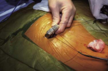
Most IPGs have two suture holes along the upper edge where nonabsorbable sutures are used to secure the IPG to a fascial plane. These sutures keep the IPG from turning in the pocket. Rotation and movement of the IPG in the pocket over time will stress the lead wires causing fracture and lead dislodgement. These sutures are best placed through a deep fascia layer and tied with 2 to 3 cm of slack. Figure 41-18 shows the IPG with silk sutures being placed. Figure 41-19 shows how placing an instrument into the loop of tie will allow the knots to be tied tightly while leaving slack in the loops to reduce failure. If these sutures are tied tightly, they tend to “saw” through the tissues over time and fail. The spinal incision and the pocket are closed with absorbable sutures in layers when appropriate.
Postoperative Measures
Antibiotics are provided during the trial period and after permanent system implantation or revision according to the implanting physician’s experience, patient needs, and type of surgery. For the average-sized adult, an antibiotic such as Keflex (cephalexin), 500 mg PO, q 6 to 8 hours unless patient is allergic or allergic to a typically cross-allergic antibiotic is appropriate. For patients with impaired immune response or known chronic infections, consultation with an infectious disease specialist may be appropriate.
Postoperative instructions include some counseling regarding possible adverse events. Epidural hematoma occurs most often early with epidural abscess occurring somewhat later after implant and developing more slowly.87
Complications
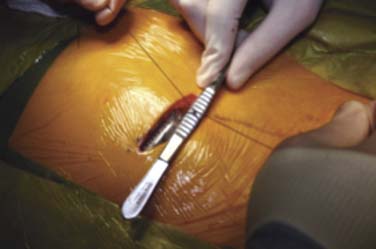
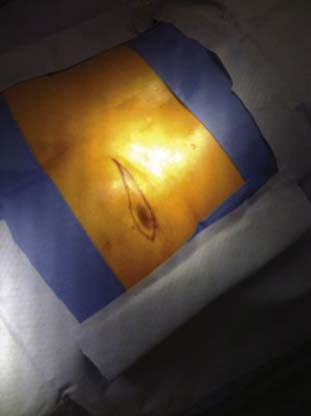
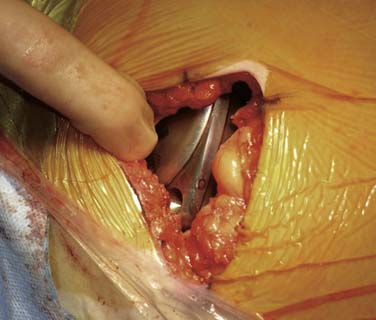
Wound healing complications include subcutaneous infection, wound dehiscence, stitch abscess formation, and deep infections. Most infections related to the surgical implant will develop in the first 4 weeks following surgery. If at any time the wound breaks down (dehisces) such that implanted components are visible, aerobic and anaerobic wound cultures must be obtained to help guide antibiotic coverage and to determine if the wound is infected or if mechanical factors led to the dehiscence. Typically, some skin contamination in a dehisced wound is cultured. If the wound is infected, most generally the system is explanted, the infection is cleared, and the patient is later evaluated for possible reimplantation. If wound dehiscence is caused by failure of the closure and the wound is not infected as determined by cultures, surgical excision of the affected skin margins, vigorous irrigation with antibiotic or dilute Betadine (povidone—iodine) solution, and secondary wound closure with PDS-type suture may be attempted. Local skin flap development will reduce the stress across an incision and lessen the incidence of dehiscence. Figure 41-20 shows a dehisced wound being marked for excision of the margins for secondary closure. The cultures and Gram stain along with clinical impressions suggested that this pocket was not infected. Abscess formation around suture material may remain limited to the subcutaneous tissue or can extend and enter deeper layers. When the device capsule is involved or if the deeper layers around a lead implant site are involved, resolution in the presence of the implanted devices is difficult.
Epidural Abscess and Hematoma
Prompt recognition and treatment of these potentially devastating complications are important. Pain (out of proportion of expected) at or below the level of the lead placement, motor or sensory loss significantly above preimplant level, fever, and chills will prompt concern. If suspicion exists for epidural abscess or hematoma in the trial patient, prompt removal of the trial leads and MRI of the spine at the appropriate spinal levels is performed. In the permanently implanted patient, CT of the appropriate spinal levels and if needed CT myelography may demonstrate an abscess or hematoma with cord compression. Currently, all device manufacturers do not approve of MRI scanning at the level of the leads. Medtronic has developed a protocol under which MRI of the head region may be performed in patients with leads placed in the thoracic area. If abscess is found, prompt surgical removal of the leads and decompression of the abscess is indicated along with antibiotic coverage. Removal of the generator may also be appropriate with lead infection complication but this is variable. Epidural hematoma is a rare but potentially devastating complication of all epidural procedures. The introducer needle can lacerate epidural vessels and the passing of a lead out of the needle with subsequent manipulation of the lead during placement can traumatize vessels. Surgical paddle lead placement also has potential for vascular damage and bleeding. The incident of bleeding and subsequent hematoma formation would be expected to be greater in patients with delayed clotting. This complication would be expected to develop within hours of implant but may develop days later. Physical examination and CT or CT myelography most often lead to proper diagnosis. In evaluating patients with trial leads, removal of the trial leads and MRI is appropriate. Prompt neurosurgical decompression of the hematoma regions may significantly improve outcome.
Intrathecal Pumps
Implanted intrathecal drug infusion uses either an electric powered and programmable pump or a pressure infused delivery device. Both devices are connected to an implanted intrathecal catheter. The drug reservoir is contained within the pump and is periodically refilled by inserting a special non-coring needle through the skin into a port located within the middle portion of the pump body. Continuous intrathecal infusion of medications offers unique advantages in the management of severe spasticity as well as chronic severe malignant and nonmalignant pain.88–93
With intrathecal delivery, drugs are deposited within the CNS more directly to target receptors in the spinal cord and, to some extent, the brain. Intrathecal delivery bypasses gut or transdermal absorption limitations and first-pass drug metabolism. Because intrathecal delivery circumvents the blood brain barrier that affects the distribution of medications into the central nervous system, much smaller doses of medications are needed to afford the desired benefits. In addition, fewer cerebral and peripheral effects are generally experienced. These benefits come at the price of system complexity, risks, and required refills.
Indications and Patient Selection
Patients suffering with chronic severe pain that is not well managed with oral or transdermal medications owing to medication side effects may also be offered an intrathecal drug trial and considered for system implantation if effective. Narcotic side effects tend to be less with continuous intrathecal administration compared to other methods of administration.94
Pump Medications
Currently the Food and Drug Administration (FDA) has approved morphine, baclofen, and ziconotide for intrathecal administration. These medications are commercially available in preservative-free formulations and are of sufficient concentration to be used alone or in combination. Many practitioners employ the services of an experienced compounding pharmacy to formulate mixtures of these and other medications that are not commercially available.95,96 Medications and mixtures not FDA approved are considered “off label” usage. Compounding pharmacies adhere to strict guidelines and test for sterility, tonicity, and pH, and they provide valuable feedback relating to the various medications being compounded. Considerations regarding drug concentrations, solubility, compatibility, and stability are important, and consultation with the compounding pharmacist is a necessity.97
Medications commonly used “off label” in intrathecal infusion include hydromorphone, clonidine, bupivacaine, fentanyl, and sufentanil. Other, less frequently utilize used “off label” medications include midazolam, meperidine, ropivacaine, neostigmine, adenosine, and ketorolac. Various drug combinations may be tried to provide optimal pain and spasticity control. Which drug or drugs to consider is often based on physician experience and the particular type of pain being managed. With the introduction of ziconotide, some treatment algorithms have changed. The reader is encouraged to research the literature and consult other physicians who are experienced in pump management when prescribing intrathecal mixtures.98,99–103
Types of Infusion Pumps
As of this writing, two companies manufacture the majority of implanted infusion pumps: Medtronic and Johnson & Johnson. Medtronic currently manufactures only the SynchroMed II (Fig. 41-21). This device is programmable and uses a motor-driven roller pump. Johnson & Johnson’s device, the Codman 3000, is a constant flow pump and uses constant gas pressure from a liquid/gas mixture of Freon (Fig 41-22).
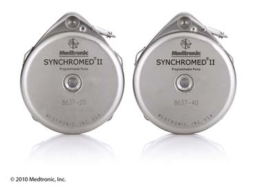
Figure 41-21 Medtronic SynchroMed II 20 mL and 40 mL programmable infusion pumps.
(Reprinted with the permission of Medtronic, Inc. ©2010.)
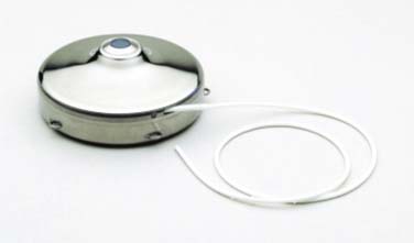
Figure 41-22 Johnson & Johnson, Codman 3000 constant flow infusion pump with attached intrathecal catheter.
Medtronic programmable infusion pumps (SynchroMed II) are FDA approved for morphine sulfate (Infumorph), baclofen (Lioresal Intrathecal) and ziconotide (Prialt). Johnson & Johnson’s Codman 3000 is FDA approved for morphine sulfate (Infumorph) and baclofen (Lioresal Intrathecal).
Intrathecal Catheters
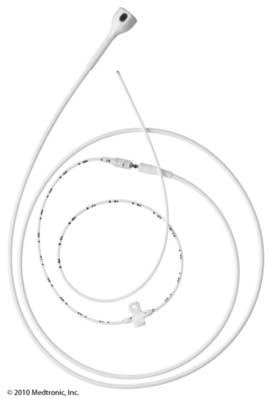
Several different catheters are or have been marketed by Medtronic. Current catheters are either a one-piece design with the same catheter dimensions the entire length or a two-piece design wherein the intrathecal or distal segment has a smaller outside dimension than the pump or proximal segment. These two segments are spliced together at the back incision region. Figure 41-23 shows the Medtronic two-piece catheter. Both Medtronic one- and two-piece catheters have the same internal diameter and a catheter volume of 0.0022 mL/cm of length. Both catheters have a radiopaque tip and six side holes near the tip. Each design has advantages and disadvantages and implanter preference generally dictates which is used. The Johnson & Johnson Codman offers the Flextip Plus catheter which is a 19 gauge one-piece design with a titanium-reinforced inner coil to resist kinking.
Preimplant Considerations
Patients with ongoing infections, bleeding dyscrasia or prolonged bleeding secondary to antiplatelet medications or chemotherapy are closely evaluated.69,104 Body mass is important when considering pump size and pocket location.
Drug Trial
Trialing intrathecal medications prior to system implant is useful and often required by payers. Baclofen is most often trialed as a single intrathecal dose of 50 to 100 mcg injected into the spinal fluid at the lower lumbar spine. If adequate benefit is not obtained with a 50 mcg dose, often a second trial of 100 mcg is considered. Ashworth or Modified Ashworth scoring of affected muscle groups is most often performed by experienced physical therapy practitioners prior to and at 30 minutes, 2, 4, and 6 hours after injection. This assists in documenting the patient’s response. The Ashworth Scale is a five-point scale (0, 1, 2, 3, or 4).105 Bohannon and Smith added a “grade 1+” to make a six-point scale and made minor changes to the definitions to increase the sensitivity. This is known as the Modified Ashworth Scale.106 Table 41-1 is a chart comparing the two Ashworth scales. A drop of at least two points is desired in either score. Other factors may also be assessed during this trial period such as frequency of spasms, increased range of motion, pain score, and changes in activities of daily living. Patients with lower extremity spasm may do worse with some ADLs such as pivot transfer where they depend on leg stiffness for support. These muscles often require long-term retraining if intrathecal baclofen infusion is instigated. A baclofen trial typically requires 6 to 8 hours to complete. Often, an initial phase of good benefit is followed by a period during which the baclofen effect is maximal and the patient is to “loose”. This is followed by another period of acceptable benefit as the baclofen effect begins to resolve and the patient returns to baseline tone.
| Score | Ashworth Scale∗ | Modified Ashworth Scale† |
|---|---|---|
| 0 | No increase in tone | No increase in muscle tone |
| 1 | Slight increase in tone giving a catch when the limb is moved in flexion or extension | Slight increase in muscle tone, manifested by a catch and release or by minimal resistance at the end of the range of motion (ROM) when the affected part is moved in flexion or extension |
| 1+ | N/A | Slight increase in muscle tone, manifested by a catch, followed by minimal resistance throughout the remainder (less than half) of the ROM |
| 2 | More marked increase in tone but limb is easily flexed | More marked increase in muscle tone through most of the ROM, but affected parts are easily moved |
| 3 | Considerable increase in tone, passive movement is difficult | Considerable increase in muscle tone, passive movement is difficult |
| 4 | Limb is rigid in flexion or extension | Affected part is rigid in flexion or extension |
Implant Process
Implantation of an intrathecal pump and catheter is a surgical procedure requiring a surgical environment and techniques as described in the previous section on spinal cord stimulator implant.107,108 The pump is most generally implanted in the lower quadrant of the abdominal region, and the catheter is inserted in the lower lumbar region with the catheter tip advanced to an appropriate spinal level. Previous abdominal surgical procedure scarring or the presence of a suprapubic urinary catheter or gastrostomy feeding tubes will affect the planned pocket location. With the patient lying supine, the proposed pocket skin incision location is marked. In adults, typically a transverse incision slightly larger than the pump is made at the level of the lower portion of the umbilicus. Pumps and catheters may be implanted using general endotracheal anesthesia or local anesthesia with sedation. Communication with the patient is not required during implantation. Patients may report pain if the spinal cord or nerve roots are contacted during introducer placement or catheter manipulation. If there is increased concern for spinal cord or nerve damage, local anesthesia may be preferred so that the patient may report.
C-arm fluoroscopy is required to verify spinal structures and level and to verify appropriate introducer placement and catheter tip location. Posteroanterior (PA) fluoroscopy imaging is initially used and the image is adjusted so that the intended insertion level is visualized in a true PA projection. The introducer is inserted below the level of the conus medullaris which is typically above L2 in adults. Figure 41-24 shows a patient in the left lateral position with the C-arm providing a PA view for placement of the intrathecal introducer. A slight paramedian introducer approach is used with as flat of an entry angle to the spine as is practical. The needle tip target is midline below the spinous process. When the introducer needle is inserted through the dura with the bevel aligned in the longitudinal axis, fewer dural fibers are cut. This may reduce the incidence of postdural puncture headache. The introducer is advanced using lateral radiographic imaging and is stopped midway in the spinal cannel. Figure 41-25 shows a lateral fluoroscopy image of the introducer and catheter projecting cephalad. The bevel position of the needle is indicated on the hub and after entry into the intrathecal space is rotated to point cephalad. Brief removal of the stylet will demonstrate copious CSF flow from the needle and is quickly replaced so as not to allow a large volume of CSF to escape. This is especially important in the pediatric patient where spinal CSF volume is minimal. The catheter tip is held near the needle hub and is inserted as soon as the stylet is removed. Gentle pressure only is required to pass the catheter and advancement is observed in the PA and lateral fluoroscopy projections until the radiopaque tip is at the intended spinal level. Occasionally as the catheter emerges from the introducer tip, it touches the anterior wall of the spinal canal. If this occurs, withdrawing the introducer slightly may allow the catheter to pass. Withdrawing a catheter from the introducer can result in sheering of the catheter. When a catheter fails to advance easily, remove the introducer and catheter together. The introducer can be reinserted at the same or different spinal level.
A longitudinal incision is made against the needle and carried down to the fascia overlying the spinous processes. Blunt dissection is carried out to expose the site where the needle pierces the spinal fascia. A purse-string of nonabsorbable suture such as 0-silk is placed around the needle barrel incorporating the fascia. Figure 41-26 demonstrates a purse-string of 0-silk being placed around an introducer. The introducer is removed with the catheter stylet in place. After radiographic verification of the location of the catheter tip is made, the purse-string is tightened. When the stylet is removed, clear CSF should easily drip from the catheter. Occasionally, the CSF may require aspiration using a “Luer–Slip” tuberculin syringe at the pump connector end. A suitable anchor is slid onto the catheter and secured to the fascia with nonabsorbable suture as per manufacturer recommendations. When using a two-piece catheter, the spinal segment is typically trimmed and a protective “boot” is slid onto the spinal segment. The spinal and pump segments are connected by a titanium pin from the thicker pump segment. Care is taken when making this connection because damage to the catheter may occur causing a hole and persistent CSF leakage with loss of benefit. Using a one-piece catheter does not generally require a splice at the spine but a pump connector is attached to the end of the catheter using nonabsorbable suture.
A pocket is developed following incision of the skin at the previously marked site down to the subcutaneous fat layer. Blunt finger dissection and electrocautery is used in the subcutaneous fat tissue plane. The pocket is often placed toward midline and lower in the abdomen and pelvis. It is best to anchor pumps to the deep fascia, however, in very obese patients it may not be practical to place the pump against the abdominal fascia. In some circumstances, a pocket is developed within the subcutaneous fat layer. Pumps placed within a thick fat layer deep to the skin may be difficult to refill, are at increased risk of flipping or turning, and if programmable, they may be hard to communicate with because of the distance.
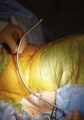
A hollow tunneling device is passed from the back incision to the pocket if using a two-piece catheter and from the pocket to the back incision when using a one-piece catheter. The tunneling device may be bent to conform somewhat to the intended path dimensions (Fig. 41-27) Alternately, the tunneling device may be passed to an intermediate incision located in the lower flank region using two separate passes.
Nonabsorbable sutures are used to anchor the pump in the pocket. Three or four, typically 0-silk, are placed into the deep fascia and passed through corresponding suture loops. These sutures prevent the pump from rotating, flipping, and migrating laterally. The catheter connecter is secured to the pump as per manufacture recommendations. The catheter is coiled and held behind the pump and they are both gently placed into the pocket making sure the sutures do not directly touch the catheter. The ends of a pair of forceps may be placed into the loop of suture prior to tying several knots to create approximately 2 cm of slack. If these sutures are tied tightly, they tend to “saw” through the tissue with pump movements. Figure 41-28 shows a pump in the pocket ready for skin closure.
Postoperative Complications
Pump pocket wound healing complications are reduced by proper pocket creation, local flap development when needed, and closure with minimal stress at the incision. Even superficial infections may progress to involve deeper levels and the pocket. When infection of the pocket occurs, removal of the pump and catheter is warranted. An infection of the pump pocket can tract down the catheter path and involve the catheter implant site. Some reports of successful infection treatment “salvaging” the device have been given. These efforts are undertaken by experienced implant groups with knowledge of the risks and benefits of such attempts.107–111
Refilling the Pump Reservoir
The computer within the Medtronic SynchroMed II calculates the expected pump volume based on the input volume at time of refill and the programmed infusion rate. The pump does not have a volume sensor. It will continue to infuse at the programmed rate until nearly empty. At a volume below 1.0 mL the infusion becomes gradually less and at a volume below approximately 0.6 mL, the infusion stops. There is a residual 1.4 mL within the pump that cannot be aspirated or pumped out. This residual drug may be important when drug concentration changes are made and is the reason Medtronic advises that the reservoir be rinsed with the new drug prior to refill when a significant drug concentration change is made. The infusion will continue at the set rate until the reservoir is empty regardless of the calculated volume.
Managing Patients with Intrathecal Infusion Pumps
There is considerable variation among practices managing intrathecal drug infusion and the “art” of pump management is developed with experience. Long-term management of patients with intrathecal pumps containing narcotics is not simply to increase the dose. Continuous dose escalation of narcotics will lead to tolerance. A “hyperalgesic” state may also develop when narcotic dosage is very high. As with any delivery route, chronic high-dose narcotic administration appears to inhibit the usual pain control mechanism.112–127a A few practitioners advocate using low doses of intrathecal morphine (less than 0.5 mg/day) to avoid some of the complications associated with dose escalation.
Tolerance problems appear to be less with intrathecal baclofen and ziconotide.128,129 After attaining a stable infusion rate, dose escalation is not typically required to provide the same clinical efficacy. Infusion rates of these medications require only occasional adjustment when disease or health state changes are thought to be long term in nature.
Infusion System Failure
Ongoing management of patients with intrathecal infusion systems by knowledgeable health care professionals is a valuable first source of information indicating there may be a malfunction. Between refills and especially at the time of refill, patients and patient care providers report or are questioned regarding symptoms and perceived benefits.130 If significant changes in benefit are reported, suspicion is raised and attention is given to the possibility of a system malfunction. Multiple factors will affect medication benefit and include patient illness, physical and psychological stress, medication changes, and disease progression or remission. Patient history and past issues at times of refills are also important. These are factored together with the physician’s personal knowledge of the patient to formulate an impression regarding how to proceed.
When a patient suffers a profound reduction in benefit, there are several considerations. Symptom onset shortly after refill may indicate pump programming or drug errors. The refill event is reviewed, and if the pump is programmable, it is interrogated and the programming is confirmed. Instilled medication prescription is reviewed and if compounded medication was used, the compounding pharmacy is contracted to verify the prescription and the compounded medication that was supplied. Supportive care is instituted as indicated. This may include increased oral pain medication or oral baclofen. Patients will, on occasion, require hospitalization for parenteral antispasmodic or pain medications and on rare incidences, placement of a temporary intrathecal catheter to restart the intrathecal infusion.131 Often, prompt surgical correction of a catheter defect or replacement of a failed pump is best.
Catheter Failure
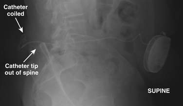
Plain AP and lateral radiographs of the pump and the entire catheter are useful to demonstrate if complete catheter fracture or dislodgement has occurred. Figure 41-29 shows a lateral radiograph whereon a catheter has pulled out of the intrathecal space and is coiled within the back implant region. This complication likely resulted from anchoring within the subcutaneous tissues and not at the spinal fascia. These radiographs cannot with certainty demonstrate catheter kinks or defects that do not cause complete catheter fracture.
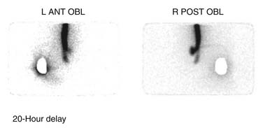
If contrast spread is intrathecal, then reasonable assurance is made that the catheter is continuous, but this study cannot rule out the presence of small catheter defects. With small defects, the contrast can pass down the catheter into the intrathecal space without enough contrast passing out the defect to be easily detected. In this situation, an indium DTPA In 111 study may be useful to demonstrate the defect.132–134 This nuclear medicine study uses radioactive indium DTPA 111 (0.5 to 2 mCi) placed into the pump reservoir. The pump is allowed to infuse at its usual rate and the flow of indium is documented by serial scans over a period of time depending on the pump flow rate. The indium DTPA In 111 study can be accomplished without interrupting normal medication delivery or alternately the pump contents can be emptied and the indium DTPA In 111 can be added to saline placed into the pump. Indium DTPA In 111 will collect at a site where pump contents exit the catheter. Figure 41-30 demonstrates a small collection of indium DTPA In 111 at the spinal implant site and a large amount being infused into the spinal canal. This was a very small defect and was positional. With an intact catheter the indium DTPA tracer will be seen within the spinal canal. It is useful to place a lead blank or shield over the pump to reduce the tracer count the camera sees to improve the signal-to-noise ratio. In special situations, and using great care, a very small aliquot (less than 0.05 mL) of indium DTPA has been injected directly into the catheter access port and the pump has been allowed to run at its usual rate. In doing this, the tracer is only present in the catheter which considerably reduces the background noise and provides improved resolution. The risk of this technique is that when the catheter access port is injected, contents of the catheter are displaced. This can result in significant overdosing. This technique can be useful in those situations where the catheter dye study is apparently normal but a catheter failure is still of concern. After the dye study, the catheter is free of medication and a small aliquot of indium DTPA 111 can more safely be placed into the catheter. Indium DTPA 111 half-life is 2.83 days or 67.9 hours and is predominantly excreted in the urine. Rapid appearance of counts in the kidneys and the bladder is noted after the indium DTPA exits the catheter.
Fluid accumulation at the spinal catheter insertion site or the pump pocket may indicate a CSF leak from a defect in the catheter. CSF pressure is transmitted down the catheter to the location of a defect. The flow rate from an intrathecal implanted pump is very small and if any defect along a catheter develops, CSF and pump medications will flow out of the defect. This generally causes complete loss of benefit and often an accumulation of CSF at the site. CSF may track along the external surface of a catheter and accumulate at a distant site. Occasionally CSF leakage at the spinal insertion site or at a catheter splice or anchor in the back can track around the catheter tissue sheath and enter the pump pocket resulting in CSF collection.
Other considerations for fluid collection would include seroma and infection. Generally, seroma and CSF accumulations are not associated with redness or skin temperature elevation. Early after implant, seroma accumulation is common and generally of little consequence. Aspiration of seroma fluid is avoided because the procedure has the potential of introducing bacteria into the area. If an infection is suspected, prompt aspiration of the fluid with appropriate Gram stain and culture will help direct antibiotic care. When a deep infection is diagnosed, prompt removal of the pump and catheter is advised. Eradication of an infection in the presence of implanted devices is very difficult and in the presence of an intrathecal catheter additional risks of CNS spread are imparted.107,108,111,135–137 If a fluid collection is suspected to contain CSF, a beta-2 transferrin assay can be useful. Beta-2 transferrin is a protein found almost exclusively in the CNS and spinal fluid.138
Persistent postural headache may arise as a result of CSF leakage around the catheter where it pierces the dura. This complication is reduced with the application of a purse-string suture placed around the introducer needle prior to its removal at time of implant.139 An x-ray-guided epidural blood patch may be helpful, understanding that this procedure carries some increased infection risk and the possibility of blood entering the intrathecal space.140–143 In persistent cases, surgical exploration of the implant area looking for possible catheter sources of the CSF leakage is recommended. This provides an opportunity to possibly witness CSF flow around the catheter where it enters the ligament or fascia. CSF leakage around the catheter may be accentuated by applying increased intrathoracic pressure by a Valsalva maneuver. On occasion, the solution is to remove the catheter, over-sew the area to close the site where the catheter pierced the ligament or fascia, and place another catheter.
When catheters fracture at the interspinal ligament, most often the fragment will migrate into the intrathecal space. Unless the fragment causes some neurologic sequela, it most frequently is left in the intrathecal space and attempts to retrieve it are not made. Antibiotic effectiveness may be reduced in CNS infections when retained fragments are present.144,145
Catheter Tip Inflammatory Mass
Patients presenting with relatively sudden or unexplained decreased therapeutic response, pain, neurologic changes such as weakness and reflex changes should be evaluated for the presence of a mass at the catheter tip.146 These masses are not well understood but appear to be associated more with the infusion of highly concentrated narcotic preparations. The incidence is expected to be greater than 0.5% of all intrathecal catheters and has been reported with morphine and, to a lesser degree, with baclofen.147–151 Catheter granulomatous or inflammatory masses appear to develop over time and may compress the spinal cord. Diagnosis is best made using a high-resolution MRI scanner. Gadolinium contrast may demonstrate enhancement of the mass, suggesting its inflammatory nature. Where MRI is contraindicated or not available, CT myelography of the catheter tip region may be useful. Plain radiograph examination prior to MRI or CT is used to direct the scans to the area of most interest near the catheter tip. Scanning two spinal levels above and three levels below the catheter tip usually is sufficient. The proper management of a catheter tip mass, although debated generally, includes neurosurgical consultation. Cord compression resulting in significant neurologic compromise typically is treated by prompt neurosurgical removal of the intrathecal mass along with the catheter. When neurologic symptoms allow, pulling back the catheter to a location below the mass and changing the pump drug mixture may be enough to allow resolution.
1. Melzack R., Wall P.D. Pain mechanisms: A new theory. Science. 1965;150:971-979.
2. Kunnumpurath S., Srinivasagopalan R., Vadivelu N. Spinal cord stimulation: Principles of past, present and future practice: a review. J Clin Monit Comput. 2009;23(5):333-339.
3. Nnoaham K.E., Kumbang J. Transcutaneous electrical nerve stimulation (TENS) for chronic pain. Cochrane Database Syst Rev, 16. 2008;:CD003222.
4. Poitras S., Brosseau L. Evidence-informed management of chronic low back pain with transcutaneous electrical nerve stimulation, interferential current, electrical muscle stimulation, ultrasound, and thermotherapy. Spine J. 2008;8(1):226-233.
5. Shealy C.N., Mortimer J.T., Reswick J.B. Electrical inhibition of pain by stimulation of the dorsal columns: preliminary clinical report. Anesth Analg. 1967;46(4):489-491.
6. Nielson K.D., Adams J.E., Hosobuchi Y. Experience with dorsal column stimulation for relief of chronic intractable pain: 1968-1973. Surg Neurol. 1975;4(1):148-152.
7. Oakley J.C., Prager J.P. Spinal cord stimulation: mechanisms of action. Spine. 2002;27(22):2574-2583.
8. Holsheimer J., Wesselink W.A. Optimum electrode geometry for spinal cord stimulation: the narrow bipole and tripole. Med Biol Eng Comput. 1997;35:493-497.
9. Buonocore M., Bonezzi C., Barolat G. Neurophysiological evidence of antidromic activation of large myelinated fibres in lower limbs during spinal cord stimulation. Spine. 2008;33(4):E90-E93.
10. Cui J.G., O’Connor W.T., Ungerstedt U., et al. Spinal cord stimulation attenuates augmented dorsal horn release of excitatory amino acids in mononeuropathy via a GABAergic mechanism. Pain. 1997;73(1):87-95.
11. Mazzone P., Rodriguez G., Arrigo A., et al. Cerebral haemodynamic changes induced by spinal cord stimulation in man. Ital J Neurol Sci. 1996;17(1):55-57.
12. Linderoth B., Stiller C.O., Gunasekera L., et al. Gamma-aminobutyric acid is released in the dorsal horn by electrical spinal cord stimulation: a in vivo microdialysis study in the rat. Neurosurgery. 1994;34(3):484-488.
13. Simpson R.K.Jr., Robertson C.S., Goodman J.C., Halter J.A. Recovery of amino acid neurotransmitters from the spinal cord during posterior epidural stimulation: a preliminary study. J Am Paraplegia Soc. 1991;14(1):3-8.
14. Yakhnitsa V., Linderoth B., Meyerson B.A. Spinal cord stimulation attenuates dorsal horn neuronal hyperexcitability in a rat model of mononeuropathy. Pain. 1999;79(2-3):223-233.
15. Computer Modeling of Spinal Cord Stimulation for Low Back Pain. White Paper Prepared by Medtronic. 1–10. Medtronic; 2007.
16. Henderson J.M. Peripheral nerve stimulation for chronic pain. Curr Pain Headache Rep. 2008;12(1):28-31.
17. Goyal G.N., Gupta D., Jain R., et al. Peripheral nerve field stimulation for intractable post-thoracotomy scar pain not relieved by conventional treatment. Pain Pract. 2010;10:366-369.
18. Paicius R.M., Bernstein C.A., Lempert-Cohen C. Peripheral nerve field stimulation in chronic abdominal pain. Pain Physician. 2006;9(3):261-266.
19. Meyerson B.A. Neurosurgical approaches to pain treatment. Acta Anaesthesiol Scand. 2001;45(9):1108-1113.
20. Bala M.M., Riemsma R.P., Nixon J., Kleijnen J. Systematic review of the (cost-)effectiveness of spinal cord stimulation for people with failed back surgery syndrome. Clin J Pain. 2008;24(9):741-756.
21. Devulder J., De Laat. M., Van Bastelaere. M., Rolly G. Spinal cord stimulation: a valuable treatment for chronic failed back surgery patients. J Pain Symptom Manage. 1997;13(5):296-301.
22. Frey M.E., Manchikanti L., Benyamin R.M., et al. Spinal cord stimulation for patients with failed back surgery syndrome: a systematic review. Pain Physician. 2009;12(2):379-397.
23. Nicholson C.L., Korfias S., Jenkins A. Spinal cord stimulation for failed back surgery syndrome and other disorders. Acta Neurochir Suppl. 2007;97:71-77.
24. North R.B., Kidd D.H., Lee M.S., Piantodosi S. A prospective, randomized study of spinal cord stimulation versus reoperation for failed back surgery syndrome: initial results. Stereotact Funct Neurosurg. 1994;62(1-4):267-272.
25. North R.B., Kidd D.H., Piantadosi S. Spinal cord stimulation versus reoperation for failed back surgery syndrome: A prospective, randomized study design. Acta Neurochir Suppl. 1995;64:106-108.
26. North R.B., Kidd D., Shipley J., Taylor R.S. Spinal cord stimulation versus reoperation for failed back surgery syndrome: a cost effectiveness and cost utility analysis based on a randomized, controlled trial. Neurosurgery. 2007;61(2):361-368.
27. Taylor R.S. Spinal cord stimulation in complex regional pain syndrome and refractory neuropathic back and leg pain/failed back surgery syndrome: Results of a systematic review and meta-analysis. J Pain Symptom Manage. 2006;31(suppl 4):S13-S19.
28. Van Buyten J.P. Neurostimulation for chronic neuropathic back pain in failed back surgery syndrome. J Pain Symptom Manage. 2006;31(suppl 4):S25-S29.
29. Williams K.A., Korto K., Cohen S.P. Spinal cord stimulation: “neural switch” in complex regional pain syndrome type I. Pain Med. 2009;10(4):762-766.
30. Simpson E.L., Duenas A., Holmes M.W., et al. Spinal cord stimulation for chronic pain of neuropathic or ischaemic origin: systematic review and economic evaluation. Health Technol Assess. 2009;13(17):1-154.
31. Kemler M.A., de Vet H.C., Barendse G.A., et al. Effect of spinal cord stimulation for chronic complex regional pain syndrome Type I: five-year final follow-up of patients in a randomized controlled trial. J Neurosurg. 2008;108(2):292-298.
32. Cruccu G., Aziz T.Z., Garcia-Larrea L., et al. EFNS guidelines on neurostimulation therapy for neuropathic pain. Eur J Neurol. 2007;14(9):952-970.
33. Lee A.W., Pilitsis J.G. Spinal cord stimulation: indications and outcomes. Neurosurg Focus. 2006;21(6):E3.
34. De Andrés .J., Van Buyten J.P. Neural modulation by stimulation. Pain Pract. 2006;6(1):39-45.
35. Stanton-Hicks M.D., Burton A.W., Bruehl S.P., et al. An updated interdisciplinary clinical pathway for CRPS: report of an expert panel. Pain Pract. 2002;2(1):1-16.
36. Stanton-Hicks M. Complex regional pain syndrome: manifestations and the role of neurostimulation in its management. J Pain Symptom Manage. 2006;31(suppl 4):S20-S24.
37. Harke H., Gretenkort P., Ladleif H.U., Rahman S. Spinal cord stimulation in sympathetically maintained complex regional pain syndrome type I with severe disability. A prospective clinical study. Eur J Pain. 2005;9(4):363-373.
38. Iseki M., Morita Y., Nakamura Y., et al. Efficacy of limited-duration spinal cord stimulation for subacute postherpetic neuralgia. Ann Acad Med Singapore. 2009;38(11):1004-1006.
39. Harke H., Gretenkort P., Ladleif H.U., et al. Spinal cord stimulation in postherpetic neuralgia and in acute herpes zoster pain. Anesth Analg. 2002;94(3):694-700.
40. Lazorthes Y., Siegfried J., Verdie J.C., Casaux J. [Chronic spinal cord stimulation in the treatment of neurogenic pain. Cooperative and retrospective study on 20 years of follow-up]. Neurochirurgie. 1995;41(2):73-86.
41. Meglio M., Cioni B., Rossi G.F. Spinal cord stimulation in management of chronic pain. A 9-year experience. J Neurosurg. 1989;70(4):519-524.
42. Meglio M., Cioni B., Prezioso A., Talamonti G. Spinal cord stimulation (SCS) in the treatment of postherpetic pain. Acta Neurochir Suppl. 1989;46:65-66.
43. Ansari S., Chaudhri K., Moutaery K. Neurostimulation for refractory angina pectoris. Acta Neurochir Suppl. 2007;97:283-288.
44. Eddicks S., Maier-Hauff K., Schenk M., et al. Thoracic spinal cord stimulation improves functional status and relieves symptoms in patients with refractory angina pectoris: The first placebo-controlled randomised study. Heart. 2007;93(5):585-590.
45. Aronow W.S., Frishman W.H. Spinal cord stimulation for the treatment of Angina Pectoris. Curr Treat Options Cardiovasc Med. 2004;6(1):79-83.
46. Gersbach P.A., Hasdemir M.G., Eeckhout E., von Segesser L.K. Spinal cord stimulation treatment for angina pectoris: more than a placebo? Ann Thorac Surg. 2001;72(3):S1100-S1104.
47. Fricke E., Eckert S., Dongas A., et al. Myocardial perfusion after one year of spinal cord stimulation in patients with refractory angina. Nuklearmedizin. 2009;48(3):104-109.
48. De Vries .J., De Jongste M.J., Spincemaille G., Staal M.J. Spinal cord stimulation for ischemic heart disease and peripheral vascular disease. Adv Tech Stand Neurosurg. 2007;32:63-89.
49. Aronow W.S., Frishman W.H. Spinal cord stimulation for the treatment of angina pectoris. Curr Treat Options Cardiovasc Med. 2004;6(1):79-83.
50. Di Pede .F., Zuin G., Giada F., et al. Long-term effects of spinal cord stimulation on myocardial ischemia and heart rate variability: results of a 48-hour ambulatory electrocardiographic monitoring. Ital Heart J. 2001;2:690-695.
51. Augustinsson L.E., Eliasson T., Mannheimer C. Spinal cord stimulation in severe angina pectoris. Stereotact Funct Neurosurg. 1995;65(1-4):136-141.
52. de Jongste M.J., Haaksma J., Hautvast R.W., et al. Effects of spinal cord stimulation on myocardial ischaemia during daily life in patients with severe coronary artery disease. A prospective ambulatory electrocardiographic study. Br Heart J. 1994;71(5):413-418.
53. de Jongste M.J., Staal M.J. Preliminary results of a randomized study on the clinical efficacy of spinal cord stimulation for refractory severe angina pectoris. Acta Neurochir Suppl. 1993;58:161-164.
54. Thadani U. Selection of optimal therapy for chronic stable angina. Curr Treat Options Cardiovasc Med. 2006;8(1):23-35.
55. de Vos C.C., Rajan V., Steenbergen W., et al. Effect and safety of spinal cord stimulation for treatment of chronic pain caused by diabetic neuropathy. J Diabetes Complications. 2009;23(1):40-45.
56. Kumar K., Toth C., Nath R.K. Spinal cord stimulation for chronic pain in peripheral neuropathy. Surg Neurol. 1996;46(4):363-369.
57. Francaviglia N., Silvestro C., Maiello M., et al. Spinal cord stimulation for the treatment of progressive systemic sclerosis and Raynaud’s syndrome. Br J Neurosurg. 1994;8(5):567-571.
58. Raso A.M. [Results of electrostimulation of the spinal cord in Raynaud’s disease and syndrome]. J Mal Vasc. 1989;14(1):52-54.
59. Kothari S. Neuromodulatory approaches to chronic pelvic pain and coccygodynia. Acta Neurochir Suppl. 2007;97:365-371.
60. Kapural L., Narouze S.N., Janicki T.I., Mekhail N. Spinal cord stimulation is an effective treatment for the chronic intractable visceral pelvic pain. Pain Med. 2006;7(5):440-443.
61. Deer T.R. Current and future trends in spinal cord stimulation for chronic pain. Curr Pain Headache Rep. 2001;5:503-509.
62. Kapural L., Deer T., Yakovlev A., et al. Technical aspects of spinal cord stimulation for managing chronic visceral abdominal pain: the results from the national survey. Pain Med. 2010;11:685-691.
63. Deer T.R. Current and future trends in spinal cord stimulation for chronic pain. Curr Pain Headache Rep. 2001;5(6):503-509.
64. Pinter M.M., Gerstenbrand F., Dimitrijevic M.R. Epidural electrical stimulation of posterior structures of the human lumbosacral cord: 3. Control of spasticity. Spinal Cord. 2000;38(9):524-531.
65. Cioni B., Meglio M., Prezioso A., et al. Spinal cord stimulation (SCS) in spastic hemiparesis. Pacing Clin Electrophysiol. 1989;12:739-742.
66. Maiman D.J., Mykleburst J.B., Barolat-Romana G. Spinal cord stimulation for amelioration of spasticity: experimental results. Neurosurgery. 1987;21(3):331-333.
67. Koulousakis A., Buchhaas U., Nittner K. Application of SCS for movement disorders and spasticity. Acta Neurochir Suppl. 1987;39:112-116.
68. Dimitrijevic M.M., Dimitrijevic M.R., Illis L.S., et al. Spinal cord stimulation for the control of spasticity in patients with chronic spinal cord injury: I. Clinical observations. Cent Nerv Syst Trauma. 1986;3(2):129-144.
69. Horlocker T.T., Wedel D.J., Rowlingson J.C., et al. Regional anesthesia in the patient receiving antithrombotic or thrombolytic therapy: American Society of Regional Anesthesia and Pain Medicine Evidence-Based Guidelines (Third Edition). Reg Anesth Pain Med. 2010;35(1):64-101.
70. Lai H.Y., Lee C.Y., Lee S.T. High cervical spinal cord stimulation after failed dorsal root entry zone surgery for brachial plexus avulsion pain. Surg Neurol. 2009;72(3):286-289.
71. Kreis P.G., Fishman S.M. Spinal Cord Stimulation: Percutaneous Implantation Techniques. New York: Oxford University Press; 2009.
72. Foletti A., Durrer A., Buchser E. Neurostimulation technology for the treatment of chronic pain: a focus on spinal cord stimulation. Expert Rev Med Devices. 2007;4(2):201-214.
73. Oakley J.C., Prager J.P. Spinal cord stimulation: mechanisms of action. Spine. 2002;27(22):2574-2583.
74. Krames E. Spinal cord stimulation: Indications, Mechanism of Action, and Efficacy. Curr Rev Pain. 1999;3(6):419-426.
75. Maruyama Y., Shimoji K. [Epidural spinal cord stimulation: its efficacy and mechanisms]. Gan No Rinsho. 1985;31(suppl 6):729-735.
76. Kumar K., Wilson J.R. Factors affecting spinal cord stimulation outcome in chronic benign pain with suggestions to improve success rate. Acta Neurochir Suppl. 2007;97:91-99.
77. Doleys D.M. Psychological factors in spinal cord stimulation therapy: brief review and discussion. Neurosurg Focus. 2006;21(6):E1.
78. Beltrutti D., Lamberto A., Barolat G., et al. The psychological assessment of candidates for spinal cord stimulation for chronic pain management. Pain Pract. 2004;4(3):204-221.
79. Horlocker T.T., Wedel D.J., Rowlingson J.C., et al. Regional anesthesia in the patient receiving antithrombotic or thrombolytic therapy: American Society of Regional Anesthesia and Pain Medicine Evidence-Based Guidelines (Third Edition). Reg Anesth Pain Med. 2010;35(1):64-101.
80. Tyagi A., Bhattacharya A. Central neuraxial blocks and anticoagulation: a review of current trends. Eur J Anaesthesiol. 2002;19(5):317-329.
81. North R.B., Lanning A., Hessels R., Cutchis P.N. Spinal cord stimulation with percutaneous and plate electrodes: side effects and quantitative comparisons. Neurosurg Focus. 1997;2(1):E3.
82. Devulder J., De Laat .M., Rolly G. Dual channel electrostimulation in pain. Acta Neurol Belg. 1998;98(2):195-198.
83. Buvanendran A., Lubenow T.J. Efficacy of transverse tripolar spinal cord stimulator for the relief of chronic low back pain from failed back surgery. Pain Physician. 2008;11(3):333-338.
84. Vangeneugden J. Implantation of surgical electrodes for spinal cord stimulation: classical midline laminotomy technique versus minimal invasive unilateral technique combined with spinal anaesthesia. Acta Neurochir Suppl. 2007;97:111-114.
85. Zhang K., Bhatia S., Oh M., Whiting D. Epidural anesthesia for placement of spinal cord stimulators with paddle-type electrodes. Stereotact Funct Neurosurg. 2009;87(5):292-296.
86. Lind G., Meyerson B.A., Winter J., Linderoth B. Implantation of laminotomy electrodes for spinal cord stimulation in spinal anesthesia with intraoperative dorsal column activation. Neurosurgery. 2003;53(5):1150-1153.
87. Franzini A., Ferroli P., Marras C., Broggi G. Huge epidural hematoma after surgery for spinal cord stimulation. Acta Neurochir. 2005;147(5):565-567.
88. Fields H.L. Pain II: new approaches to management. Ann Neurol. 1981;9(2):101-106.
89. Francisco G.E., Yablon S.A., Schiess M.C., et al. Consensus panel guidelines for the use of intrathecal baclofen therapy in poststroke spastic hypertonia. Top Stroke Rehabil. 2006;13(4):74-85.
90. Krames E. Implantable devices for pain control: spinal cord stimulation and intrathecal therapies. Best Pract Res Clin Anaesthesiol. 2002;16(4):619-649.
91. Krames E. Implantable devices for pain control: spinal cord stimulation and intrathecal therapies. Best Pract Res Clin Anaesthesiol. 2002;16(4):619-649.
92. Angel I.F., Gould H.J.Jr., Carey M.E. Intrathecal morphine pump as a treatment option in chronic pain of nonmalignant origin. Surg Neurol. 1998;49(1):92-98.
93. Paice J.A., Penn R.D., Shott S. Intraspinal morphine for chronic pain: a retrospective, multicenter study. J Pain Symptom Manage. 1996;11(2):71-80.
94. Knight K.H., Brand F.M., Mchaourab A.S., Veneziano G. Implantable intrathecal pumps for chronic pain: highlights and updates. Croat Med J. 2007;48(1):22-34.
95. Ghafoor V.L., Epshteyn M., Carlson G.H., et al. Intrathecal drug therapy for long-term pain management. Am J Health Syst Pharm. 2007;64(23):2447-2461.
96. Stearns L., Boortz-Marx R., Du Pen .S., et al. Intrathecal drug delivery for the management of cancer pain: a multidisciplinary consensus of best clinical practices. J Support Oncol. 2005;3(6):399-408.
97. Jones T.F., Feler C.A., Simmons B.P., et al. Neurologic complications including paralysis after a medication error involving implanted intrathecal catheters. Am J Med. 2002;112(1):31-36.
98. Deer T. Polyanalgesic Consensus Conference 2007: Recommendations for the Management of Pain by Intrathecal (Intraspinal) Drug Delivery: Report of an Interdisciplinary Expert Panel. Neuromodulation. 2007;10(4):300-328.
99. Lawson E.F., Wallace M.S. Current developments in intraspinal agents for cancer and noncancer pain. Curr Pain Headache Rep. 2010;14(1):8-16.
100. Kress H.G., Simpson K.H., Marchettini P., et al. Intrathecal therapy: what has changed with the introduction of ziconotide. Pain Pract. 2009;9(5):338-347.
101. Vitale V., Battelli D., Gasperoni E., Monachese N. Intrathecal therapy with ziconotide: clinical experience and considerations on its use. Minerva Anestesiol. 2008;74(12):727-733.
102. Hassenbusch S.J., Portenoy R.K., Cousins M., et al. Polyanalgesic Consensus Conference 2003: an update on the management of pain by intraspinal drug delivery—report of an expert panel. J Pain Symptom Manage. 2004;27(6):540-563.
103. Mironer Y.E. Re: polyanalgesic survey and consensus report. J Pain Symptom Manage. 2001;21(4):269-272.
104. Horlocker T.T., Wedel D.J., Benzon H., et al. Regional anesthesia in the anticoagulated patient: defining the risks (the second ASRA Consensus Conference on Neuraxial Anesthesia and Anticoagulation). Reg Anesth Pain Med. 2003;28(3):172-197.
105. Ashworth B. Preliminary trial of carisoprodol in multiple sclerosis. Practitioner. 1964;192:540-542.
106. Bohannon R.W., Smith M.B. Interrater reliability of a modified Ashworth scale of muscle spasticity. Phys Ther. 1987;67(2):206-207.
107. Albright A.L., Turner M., Pattisapu J.V. Best-practice surgical techniques for intrathecal baclofen therapy. J Neurosurg. 2006;104(suppl 4):233-239.
108. Vender J.R., Hester S., Waller J.L., et al. Identification and management of intrathecal baclofen pump complications: a comparison of pediatric and adult patients. J Neurosurg. 2006;104(suppl 1):9-15.
109. Borowski A., Littleton A.G., Borkhuu B., et al. Complications of intrathecal baclofen pump therapy in pediatric patients. J Pediatr Orthop. 2010;30(1):76-81.
110. Fjelstad A.B., Hommelstad J., Sorteberg A. Infections related to intrathecal baclofen therapy in children and adults: frequency and risk factors. J Neurosurg Pediatr. 2009;4(5):487-493.
111. Atiyeh B.S., Hayek S.N., Skaf G.S., et al. Baclofen pump pocket infection: a case report of successful salvage with muscle flap. Int Wound J. 2006;3(1):23-28.
112. Ghafoor V.L., Epshteyn M., Carlson G.H., et al. Intrathecal drug therapy for long-term pain management. Am J Health Syst Pharm. 2007;64(23):2447-2461.
113. Noble M., Treadwell J.R., Tregear S.J., et al. Long-term opioid management for chronic noncancer pain. Cochrane Database Syst Rev. (1):2010. CD006605
114. Hay J.L., White J.M., Bochner F., et al. Hyperalgesia in opioid-managed chronic pain and opioid-dependent patients. J Pain. 2009;10(3):316-322.
115. Hines S., Theodorou S., Williamson A., et al. Management of acute pain in methadone maintenance therapy in-patients. Drug Alcohol Rev. 2008;27(5):519-523.
116. Filitz J., Ihmsen H., Gunther W., et al. Supra-additive effects of tramadol and acetaminophen in a human pain model. Pain. 2008;136(3):262-270.
117. Koppert W., Schmelz M. The impact of opioid-induced hyperalgesia for postoperative pain. Best Pract Res Clin Anaesthesiol. 2007;21(1):65-83.
118. Imai S., Narita M., Hashimoto S., et al. Differences in tolerance to anti-hyperalgesic effects between chronic treatment with morphine and fentanyl under a state of pain. Nihon Shinkei Seishin Yakurigaku Zasshi. 2006;26(5-6):183-192.
119. Athanasos P., Smith C.S., White J.M., et al. Methadone maintenance patients are cross-tolerant to the antinociceptive effects of very high plasma morphine concentrations. Pain. 2006;120(3):267-275.
120. Chu L.F., Clark D.J., Angst M.S. Opioid tolerance and hyperalgesia in chronic pain patients after one month of oral morphine therapy: a preliminary prospective study. J Pain. 2006;7(1):43-48.
121. Koppert W. [Opioid-induced analgesia and hyperalgesia]. Schmerz. 2005;19:386-394.
122. Mao J., Sung B., Ji R.R., Lim G. Chronic morphine induces downregulation of spinal glutamate transporters: implications in morphine tolerance and abnormal pain sensitivity. J Neurosci. 2002;22(18):8312-8323.
123. Streltzer J. Pain management in the opioid-dependent patient. Curr Psychiatry Rep. 2001;3(6):489-496.
124. Compton P., Charuvastra V.C., Ling W. Pain intolerance in opioid-maintained former opiate addicts: effect of long-acting maintenance agent. Drug Alcohol Depend. 2001;63(2):139-146.
125. Doverty M., White J.M., Somogyi A.A., et al. Hyperalgesic responses in methadone maintenance patients. Pain. 2001;90(1-2):91-96.
126. Herrero J.F., Laird J.M., López-Garcia J.A. Wind-up of spinal cord neurones and pain sensation: much ado about something? Prog Neurobiol. 2000;61(2):169-203.
127. Crain S.M., Shen K.F. Opioids can evoke direct receptor-mediated excitatory effects on sensory neurons. Trends Pharmacol Sci. 1990;11(2):77-81.
127a. Lee M., Silverman S.M., Hansen H., Patel V.B., Manchikanti L. A comprehensive review of opioid-induced hyperalgesia. Pain Physician. 2011;14(2):145-161.
128. Heetla H.W., Staal M.J., Kliphuis C. van Laar T. The incidence and management of tolerance in intrathecal baclofen therapy. Spinal Cord. 2009;47(10):751-756.
129. McGivern J.G. Ziconotide: a review of its pharmacology and use in the treatment of pain. Neuropsychiatr Dis Treat. 2007;3(1):69-85.
130. Rawlins P.K. Intrathecal baclofen therapy over 10 years. J Neurosci Nurs. 2004;36(6):322-327.
131. Bellinger A., Siriwetchadarak R., Rosenquist R., Greenlee J.D. Prevention of intrathecal baclofen withdrawal syndrome: successful use of a temporary intrathecal catheter. Reg Anesth Pain Med. 2009;34(6):600-602.
132. Rosenson A.S. Indium-111 DTPA flow study to evaluate surgically implanted drug pump delivery system. Clin Nuclear Med. 1990;15(3):154-156.
133. Hoving M.A., Smulders N.M., Abdul Fatah. B., et al. The use of an indium111 DTPA flow study in the evaluation of a lumbar swelling in a girl with a baclofen pump. Neuropediatrics. 2006;37(2):99-101.
134. Schmidt E., Oates E. In-111 DTPA to evaluate the patency of an implanted intrathecal infusion pump. Clin Nucl Med. 1997;22(11):768-770.
135. Borowski A., Shah S.A., Littleton A.G., et al. Baclofen pump implantation and spinal fusion in children: techniques and complications. Spine. 2008;33(18):1995-2000.
136. Kallweit U., Harzheim M., Marklein G., et al. Successful treatment of methicillin-resistant Staphylococcus aureus meningitis using linezolid without removal of intrathecal infusion pump. Case report. J Neurosurg. 2007;107(3):651-653.
137. Douglas A.F., Weiner H.L., Schwartz D.R. Prolonged intrathecal baclofen withdrawal syndrome. Case report and discussion of current therapeutic management. J Neurosurg. 2005;102(6):1133-1136.
138. Skedros D.G., Cass S.P., Hirsch B.E., Kelly R.H. Beta-2 transferrin assay in clinical management of cerebral spinal fluid and perilymphatic fluid leaks. J Otolaryngol. 1993;22(5):341-344.
139. Singh P.K., Jain R., Mishra S., et al. Management of pericatheter cerebrospinal fluid leak after intrathecal implantation of a drug delivery system. Am J Hosp Palliat Care. 2008;25(3):237-239.
140. Singh P.K., Jain R., Mishra S., et al. Management of pericatheter cerebrospinal fluid leak after intrathecal implantation of a drug delivery system. Am J Hosp Palliat Care. 2008;25(3):237-239.
141. Liao Y.J., Dillon W.P., Chin C.T., et al. Intracranial hypotension caused by leakage of cerebrospinal fluid from the thecal sac after lumboperitoneal shunt placement. Case report. J Neurosurg. 2007;107(1):173-177.
142. Huch K., Kunz U., Kluger P., Puhl W. Epidural blood patch under fluoroscopic control: non-surgical treatment of lumbar cerebrospinal fluid fistula following implantation of an intrathecal pump system. Spinal Cord. 1999;37(9):648-652.
143. Kumar V., Maves T., Barcellos W. Epidural blood patch for treatment of subarachnoid fistula in children. Anaesthesia. 1991;46(2):117-118.
144. Medtronic. Medtronic: Syncromed, Isomed: Implantable Infusion Systems, Information for Prescribers. 1–34. 2009. Medtronic.
145. Forsythe A., Gupta A., Cohen S.P. Retained intrathecal catheter fragment after spinal drain insertion. Reg Anesth Pain Med. 2009;34(4):375-378.
146. Medtronic, George Aram. Updated Information—Inflammatory mass (granuloma) at or near the distal tip of intrathecal catheters. 1–8. 2008. Medtronic.
147. Deer T.R., Raso L.J., Coffey R.J., Allen J.W. Intrathecal baclofen and catheter tip inflammatory mass lesions (granulomas): a reevaluation of case reports and imaging findings in light of experimental, clinicopathological, and radiological evidence. Pain Med. 2008;9(4):391-395.
148. Hassenbusch S., Burchiel K., Coffey R.J., et al. Management of intrathecal catheter-tip inflammatory masses: a consensus statement. Pain Med. 2002;3(4):313-323.
149. Coffey R.J., Burchiel K. Inflammatory mass lesions associated with intrathecal drug infusion catheters: report and observations on 41 patients. Neurosurgery. 2002;50(1):78-86.
150. Murphy P.M., Skouvaklis D.E., Amadeo R.J., et al. Intrathecal catheter granuloma associated with isolated baclofen infusion. Anesth Analg. 2006;102(3):848-852.
151. Deer T.R. A prospective analysis of intrathecal granuloma in chronic pain patients: a review of the literature and report of a surveillance study. Pain Physician. 2004;7(2):225-228.