[level-membership-for-pulmolory-and-respiratory-category]
Review of Thoracic Imaging
After reading this chapter you will be able to:
 List the four tissue densities seen on a chest radiograph.
 Define the terms radiolucent and radiopaque.
 Describe how to evaluate the technical quality of a chest radiograph.
 State the differences between a posteroanterior chest film and an anteroposterior chest film.
 List the anatomic structures seen on a chest radiograph.
 List the steps used to interpret thoracic imaging studies.
 Identify the value of a computed tomography (CT) scan, high-resolution CT scan, and CT angiogram.
 Describe the common radiographic abnormalities seen in the pleura, lung parenchyma, and mediastinum.
 ) scans, which have been historically used in the diagnosis of pulmonary embolism. Radioisotope
 Overview of Plain Chest Radiograph
When to obtain a chest radiograph is ultimately the decision of the attending physician. However, the RT may be able to suggest that a chest x-ray should be obtained in certain circumstances, such as when a patient in the intensive care unit suddenly deteriorates for no apparent reason. The RT needs to be familiar with the common clinical indications for obtaining a chest radiograph (Box 20-1).
Approach to Reading a Plain Chest Radiograph
In broad terms, the steps in reviewing a chest film are as follows:
• Identify the name on the radiograph.
• Review the technique and quality of the film: Is the film well centered (i.e., the spinous processes are right in the middle of the trachea on a posteroanterior [PA] film), and is the amount of penetration of the beam adequate, too high (i.e., the lung parenchyma is too dark to see subtle changes), or too low (i.e., the lung parenchyma is too white, causing normal lung markings to appear abnormal)?
• Systematically review the anatomic structures on the chest film to assess their normality or abnormality.
Chest Radiograph Technique and Quality
Several technical factors should be routinely assessed when reading a chest film:
1. Is the film appropriately labeled?
2. Is the film PA with a lateral view, or is it an anteroposterior (AP) portable film?
3. Is the entire chest imaged on the film (i.e., are any structures cut off from the film)?
4. Was the patient properly positioned for the film?
5. Were the optimal settings for the x-ray beam selected when the film was taken (the term used is penetration, which is similar to exposure on camera film)?
 Problem
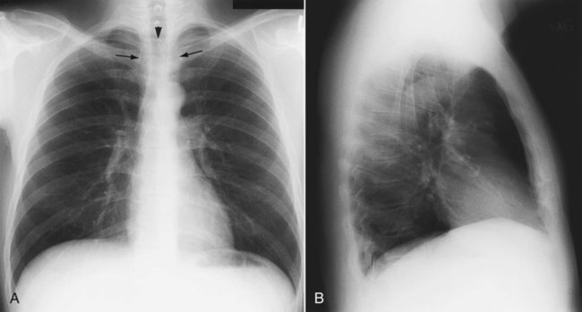
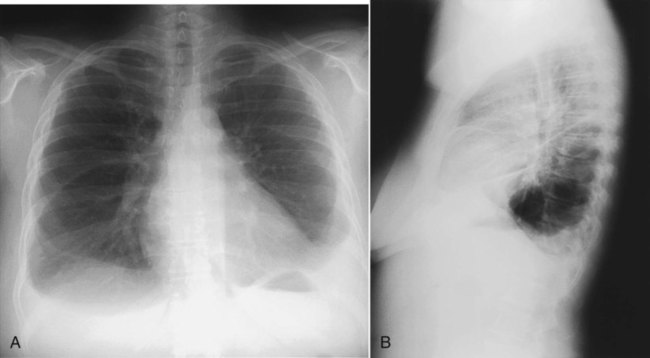
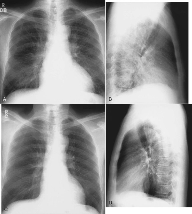
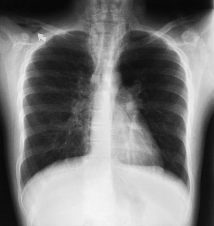
Patient rotation can make interpretation more difficult by projecting midline structures (e.g., the trachea) to the right or left. The observer can assess for rotation by comparing anterior structures such as the medial (toward the middle) ends of the clavicles with a posterior structure such as the spinous process (midline structure of the spine). In a perfectly positioned or aligned chest film, the spinous process should be seen midway between the medial ends of the clavicles and in the middle of the tracheal air column (Figure 20-1). Patient rotation makes the mediastinum appear unusually wide and obscures or distorts the appearance of the pulmonary arteries as they emerge from the mediastinum into the lung parenchyma.
Anatomic Structures Seen on a Chest Radiograph
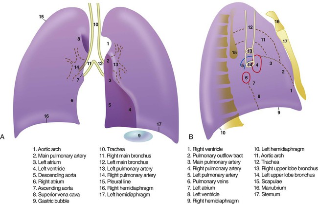
After the RT has reviewed the technical aspects of the chest radiograph, it is time to review the anatomic findings in the film. The main structures imaged on a routine chest radiograph are listed next and illustrated in Figure 20-2:
1. Bones (e.g., ribs, clavicles, scapulae, vertebrae)
2. Soft tissues (e.g., tissues of the chest wall, upper abdomen, lymph nodes)
3. Lungs (including the trachea, bronchi, and lung tissue or parenchyma)
4. Pleura (membranous coverings of the lung, including the visceral pleura [the part attached to the lungs] and the parietal pleura [the part lining the inside of the chest wall]; although normally occupied by only a small amount of fluid, the space between the parietal and visceral pleura is called the pleural space)
5. Heart, great vessels, and mediastinum (i.e., the tissues between the two lungs in the center of the chest, bordered by the sternum and the vertebral column in the AP dimension and by the thoracic inlet [where the trachea enters the thorax] and the diaphragm in the cephalocaudal direction)
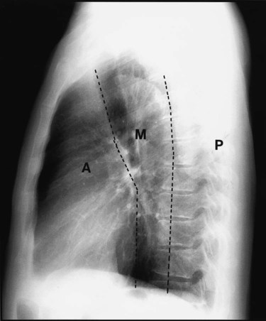
Review of the lung edge on both frontal and lateral films discloses any pleural abnormalities, such as fluid in the pleural space (e.g., hydrothorax, hemothorax [blood in the pleural space]) and air in the pleural space (pneumothorax). Evaluation of the mediastinum should include assessment of heart size. In the PA projection, the diameter of the heart shadow should not exceed one-half the diameter of the chest. An enlarged heart may occur with congestive heart failure or with a large pericardial effusion (accumulation of fluid within the space that surrounds the heart encased within the pericardium). The lateral contours of the mediastinum should correspond to normal anatomic structures as outlined in Figure 20-3.
Advanced Chest Imaging Techniques
Computed Tomography of the Chest
Computed Tomography Angiography
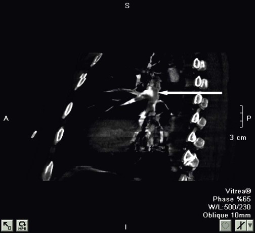
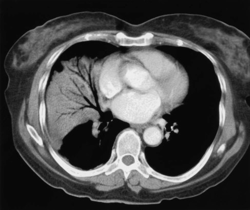
The rapid scanning that can be performed on helical CT scanners has made CT angiography possible. To perform CT angiography, a large amount of contrast dye is injected into the patient’s vein. The CT technician monitors the movement of contrast material so the scan can be started when the contrast material has entered the area to be studied. CT angiography of the chest has been used for years to identify pulmonary thromboemboli (Figure 20-4).1 More recently, CT angiography of the coronary artery has been evaluated; this seems to provide an alternative to routine coronary angiography in many patients.
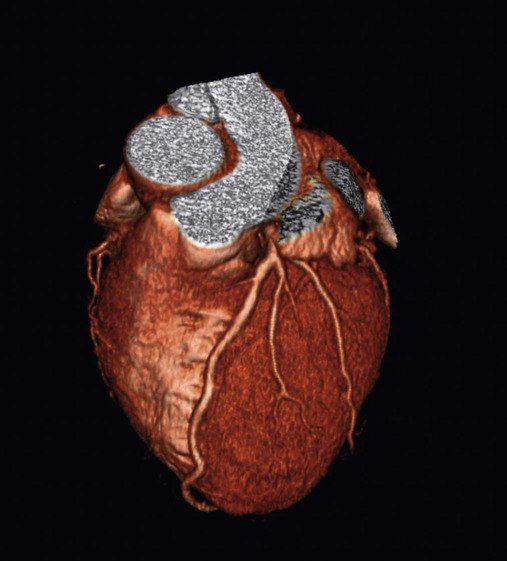
Three-Dimensional Reconstruction
The imaging processing capabilities of modern CT scanners allow reconstruction of the chest in any direction and production of three-dimensional representations of some areas of the body (Figure 20-5). The term virtual bronchoscopy is used when these reconstructions simulate the view of the airways that a physician would have during bronchoscopy.
Magnetic Resonance Imaging of the Chest
MRI also has significant limitations when applied to imaging the chest. The large magnet required for the study makes it impossible for patients with pacemakers or other significant metal objects in their bodies to undergo MRI. A patient with a small metal object, such as a surgical clip, in the brain or eye cannot undergo MRI. The powerful magnet also prevents RTs from taking metal-containing respiratory care equipment such as ventilators or gas cylinders near the MRI machine. It is crucial to avoid taking conventional metal objects near the MRI machine because the powerful magnet would pull the metallic object into the magnet with great force, exposing patients and health care providers in its path to life-threatening risk. Deaths have been reported when oversight has allowed metal objects (e.g., oxygen cylinders) to come within the magnetic field of the MRI, and RTs must be especially vigilant about this issue. Another limitation is the slow nature of the MRI process means that respiratory and cardiac motion limits its value in chest imaging. The most common uses for MRI in the chest are for imaging the mediastinum, large vessels in the lung,2 and hilar regions of the lungs.
Ultrasound
Ultrasound imaging is created by passing high-frequency sound waves into the body and detecting the sound waves that bounce back (echo) from the tissues of the body. The pattern of the returning sound waves is used to generate an image of the tissue studied. Ultrasound of the chest is excellent for evaluating the heart or pleural fluid.3 Ultrasound evaluation of the lung itself is rarely useful because of the poor ability of ultrasound to transmit through the air-filled lungs.
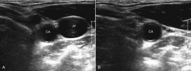
Ultrasound imaging using small portable machines has become common in critical care units. Portable ultrasound units allow rapid assessment of heart function and volume status and are used to assist in many critical care procedures.4 Ultrasound is also commonly used to guide the placement of central and arterial catheters. Blood vessels can be easily identified using ultrasound. The compressibility of veins is used to differentiate veins from arteries (Figure 20-6). Because the path the needle is taking is clearly seen on the ultrasound screen, using ultrasound guidance for venous and arterial puncture allows the procedure to be more easily accomplished with less time, risk, and patient discomfort.
 Rule of Thumb
Pleura
Hydrothorax
In healthy individuals, it is estimated that 1 to 8 ml of pleural fluid is normally present.5 Hydrothorax (also called pleural effusion) refers to the accumulation of excessive fluid within the pleural space. Normally, the diaphragm forms a dome that curves down to attach to the chest wall on the lower ribs and thoracic vertebra. On a chest radiograph, the arch of the diaphragm and the chest wall meet to form a point called the costophrenic angle. The costophrenic angle is seen on both PA and lateral views (see Figure 20-2). If the point of the costophrenic angle is rounded rather than sharp, it usually indicates a pleural effusion is present (Figure 20-7).6 For a pleural effusion to cause blunting of the costophrenic angle on the frontal view, at least 175 to 200 ml of pleural fluid must have accumulated. The lateral film detects smaller pleural effusions than are detected with the frontal view. The posterior costophrenic angle becomes blunted with 75 to 100 ml of fluid. The best film for detecting small amounts of pleural fluid is the lateral decubitus view, which is a frontal view taken as the patient is lying on the side of the suspected effusion; 5 ml of pleural fluid can be detected on a decubitus radiograph.7
Sometimes, fluid can accumulate between the lung and the diaphragm and maintain a sharp costophrenic angle, hiding 500 ml of fluid.8 Fluid that accumulates between the lung and the diaphragm is said to be in a subpulmonic location. The subpulmonic location is the first place pleural effusions accumulate in an upright patient.9 The earliest sign of a left-sided pleural effusion on an upright chest radiograph is an increased distance between the inferior margin of the left lung and the stomach gas bubble. With a subpulmonic effusion, there may be an associated slight lateral shift of the point at which the diaphragm dips downward on the frontal chest radiograph (i.e., similar to a hockey stick with the blade toward the lateral chest wall).
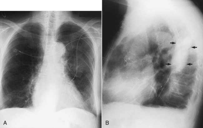
If both air and fluid are contained within the same space, the interface between the air and the fluid forms a soft tissue density with a straight, level border that has air density above it. The interface may have a small meniscus on both sides. These straight, level interfaces between air and fluid are called air-fluid levels. An air-fluid level in the pleural space indicates a hydropneumothorax (Figure 20-8).
Occasionally, fluid occupies an unusual position, such as within an interlobar fissure (which separates lobes of the lung). Fluid is most commonly seen in the minor fissure, which is between the right middle lobe and the right upper lobe. Fluid within a fissure can be diagnosed on a chest radiograph by a characteristic lenslike, elliptic shape on either the PA or the lateral projection (Figure 20-9).
An increased volume of fluid generally is categorized as either a transudate or an exudate (see Chapter 25), but an exudate cannot be distinguished from a transudate on a chest radiograph. This distinction requires analyzing a sample of the pleural fluid. Loculation of pleural fluid (or trapping so that the fluid does not move freely with changing positions) is more commonly seen in exudative effusions, hemothorax (blood in the pleural space), and empyema (infection of the pleural fluid).
Ultrasound for Evaluating Pleural Fluid
Ultrasound reliably detects small pleural effusions. It is also very useful in separating pleural fluid from solid tissue10 and readily identifies tissue bands associated with loculated effusions. Ultrasound is also helpful in guiding thoracentesis, in particular, for small or loculated pleural effusions.
Computed Tomography
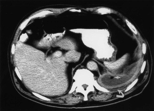
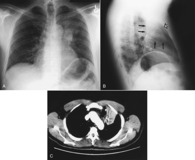
The pleural lining is enhanced by contrast media with some forms of pleural disease. Pleural thickening and nodularity are well seen with contrast-enhanced CT scan. An elliptic pleural fluid collection with thickening and enhancement of the surrounding pleura suggests an empyema, which is infected pleural fluid.11 The presence of gas bubbles within the fluid without prior surgery or needle insertion (which can introduce air) establishes the diagnosis of empyema (Figure 20-10).
Pneumothorax
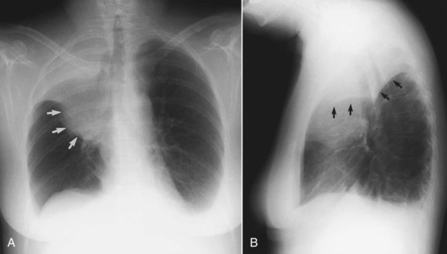
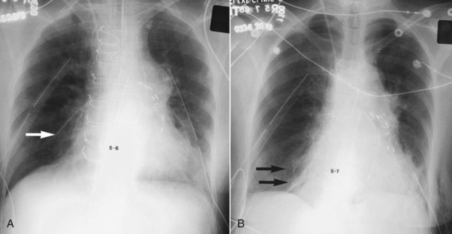
The term pneumothorax refers to the collection of air within the pleural space. The visceral pleura surrounding the lung becomes visible when air accumulates in the pleural space. Pneumothorax may occur spontaneously because of rupture of a bleb (a gas-containing space within the visceral pleura of the lung—a form of pulmonary air cyst) or may result from trauma or an invasive procedure that punctures the pleura, such as a transbronchial biopsy or percutaneous aspiration lung biopsy. Pneumothorax may also occur as a complication of positive pressure ventilation (which is called barotrauma). When the patient is upright, the intrapleural air accumulates over the top of the lung (apex) and pushes the lung away from the chest wall. The clinician can easily detect a pneumothorax by seeing the thin pleural line at the lung margin and noting the absence of bronchovascular markings between the lung margin and the inner aspect of the chest wall (Figure 20-11). If a diagnosis of pneumothorax is suspected, an upright chest radiograph should be obtained. Visualizing a small pneumothorax may be assisted by taking the chest radiograph when the patient exhales.
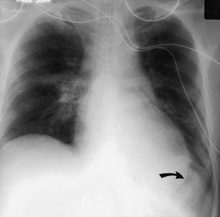
When the patient is supine, the free air in the pleural space moves to the highest point in the chest, which is the anterior cardiophrenic sulcus (see Figure 20-1).12 Because air in this region does not create a visible edge between the pleura and the x-ray beam, radiographic clues to the presence of pneumothorax are more subtle in a supine patient.12 A supine patient with a pneumothorax may have a deep sulcus sign (Figure 20-12),13 which refers to air accumulating anteriorly and outlining the heart border below the dome of the diaphragm. In addition, the upper abdomen on the same side often shows increased lucency. If the diagnosis remains in doubt, a decubitus radiograph or a cross-table lateral radiograph (in which the patient lies face up while the x-ray is directed across the body) can help make the diagnosis of pneumothorax.
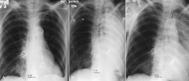
Occasionally, air within the pleural space may be under pressure or tension (Figure 20-13); this is called a tension pneumothorax. Tension pneumothorax is an emergency that occurs when the tear in the pleura (which allows air to leave the lung and enter the pleural space) opens on inspiration but closes on expiration. Air continues to accumulate in the pleural space and can compress the heart and adjacent lung. A tension pneumothorax is suggested on chest films when the hemidiaphragm is pushed down inferiorly or when the mediastinum is shifted toward the opposite lung. A tension pneumothorax requires immediate decompression with a chest tube, Heimlich valve, or needle aspiration of the trapped air.
 Problem
Lung Parenchyma
Alveolar Disease
These shadows, or opacities, often have lucent tubular visible structures running through them that represent air bronchograms (Figure 20-14). Normally, patent airways are invisible in the outer two-thirds of the lung on a chest radiograph. There is no contrast between air in the airway and air in the lung. However, the increased contrast produced by filling of the surrounding alveoli with fluid makes the airways more visible and causes the air bronchogram sign. Air bronchograms are the hallmark of infiltrates that fill alveoli (so-called airspace disease) (Figure 20-15 and Box 20-2).
 Rule of Thumb
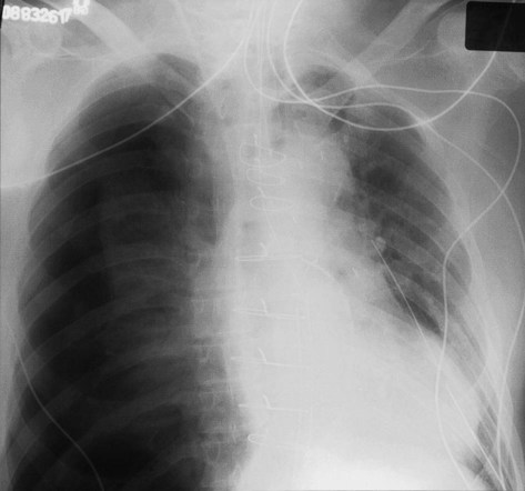
Pulmonary Edema
Pulmonary edema is one of the most common chest film findings in critically ill patients. Pulmonary edema can be caused by vascular congestion, loss of integrity of the pulmonary capillaries, or some combination of both factors. Edema from vascular congestion can be caused by failure of the left heart (cardiogenic pulmonary edema), renal failure, or fluid overload. Breakdown in the integrity of the lung capillaries can also cause pulmonary edema as in acute respiratory distress syndrome (ARDS; see Chapter 27).
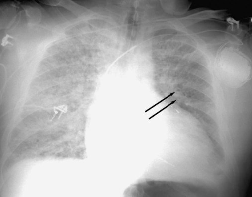
The development of cardiogenic pulmonary edema can be described through a series of changes on the chest film. Before pulmonary edema develops, the pressure in the pulmonary veins increases. The increasing pressure in the pulmonary veins can be seen on the chest film as enlarging blood vessels to the apices of the lungs. If the blood vessels to the apices of the lungs are the same size or larger than the blood vessels to the base, the vessels are said to be “cephalized” (Figure 20-16). Cephalization of the pulmonary blood flow is often caused by left-sided heart failure.
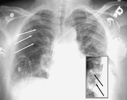
As fluid builds up from the high venous pressures, thickening of bronchial walls (peribronchial cuffing) (see Figure 20-16) and edema in the septa that separate the lung lobules become evident. The thickened septa are most clearly seen as thin lines against the pleural edge that run perpendicularly away from the pleural edge. These lines are called Kerley B lines (Figure 20-17).
 Rule of Thumb
Radiographic signs of cardiac decompensation include the following:
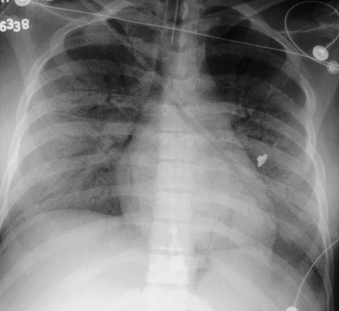
The development of edema in the lung itself is seen first in the hila of the lungs by blurring the normally distinct walls of the hilar blood vessels; this is followed by blurring and increased haziness caused by the edema progressing outward toward the pleura. The term bat’s wing appearance is applied to the predominance of edema in the hilar regions of both lungs with progressively less edema in the more peripheral areas of the lungs (Figure 20-18).
Interstitial Disease
Diseases that mainly involve the interstitium of the lung have a different radiographic appearance than alveolar diseases (see Box 20-2). The interstitium of the lung represents the part of the lung that frames the airspaces and supports the vessels and bronchi as they travel through the lung. A pulmonary lobule is the smallest functional unit of the lung.14 A pulmonary lobule contains alveoli and alveolar ducts built around a central pulmonary arteriole and bronchiole, all surrounded by a thin sheet of fibrous connective tissue called the intralobular septa. Intralobular septa are invisible on a normal chest radiograph. Pulmonary edema secondary to poor left-sided heart function causes edema of the intralobular septa. As noted, short thin lines from the edematous intralobluar septa can be seen perpendicular to the pleura (see Figure 20-16); these are Kerley B lines.
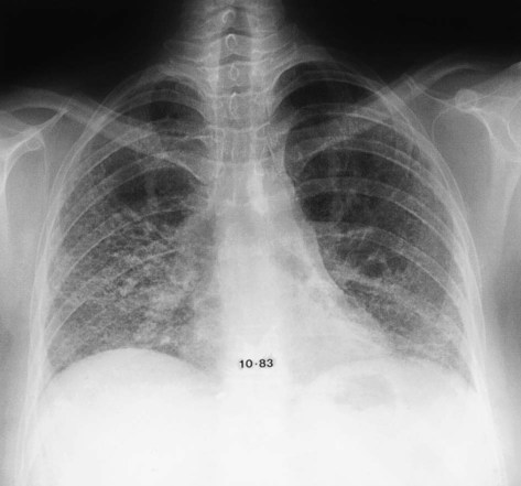
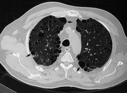
Interstitial lung disease (see Chapter 24) refers to a group of diseases that involve the lower respiratory tract. Chest radiographs of patients with interstitial lung disease may have several different appearances, depending on the stage and type of interstitial lung disease (see Box 20-2). A chest radiograph of a patient with interstitial lung disease usually has diffuse, bilateral infiltrates. The infiltrates may resemble scattered, ill-defined nodules (nodular); a collection of scattered lines (reticular); a combination of both nodules and lines (reticular-nodular); or honeycombing, which is the development of cystic spaces with well-defined walls seen in the periphery of the lung and resembling a bee’s honeycomb. Honeycombing is thought to represent irreversible scarring and indicates end-stage lung disease (Figure 20-19).
There are many types of interstitial lung disease. Causes include infectious (e.g., viral pneumonia) or occupational exposures (e.g., to asbestos [asbestosis] or to silica [silicosis]). The two most common interstitial lung diseases, sarcoidosis and idiopathic pulmonary fibrosis, have no known cause.15 Because many different types of interstitial lung diseases have the same appearance on a chest radiograph, the chest film rarely helps establish the specific cause of interstitial disease. Clues to specific causes of interstitial lung disease on a plain chest film are reviewed in Table 20-1. HRCT has become an important tool in establishing the specific form of interstitial lung disease that a patient may have. HRCT is particularly helpful in diagnosing idiopathic pulmonary fibrosis.16
TABLE 20-1
Clues on Plain Chest Radiograph That Indicate the Specific Cause of Interstitial Lung Disease
| Clues on Radiograph | Cause of Disease |
| Pneumothorax | Lymphangioleiomyomatosis, Langerhans cell histiocytosis |
| Pleural effusion | Rheumatoid arthritis, systemic lupus erythematosus |
| Dilated esophagus | Scleroderma, CREST syndrome* |
| Erosive arthropathy (shoulder joints, clavicles) | Rheumatoid arthritis |
| Mediastinal adenopathy | Sarcoidosis, scleroderma, metastatic cancer |
| Soft tissue calcification | Dermatomyositis, scleroderma |
| Pleural plaque | Asbestosis |
*Calcinosis cutis, Raynaud phenomenon, esophageal dysfunction, sclerodactyly, and telangiectasia.
Assessing Lung Volume
Volume loss, or atelectasis, is a common abnormality on chest radiographs, and the location and extent of volume loss produce characteristic chest radiograph patterns. Atelectasis may be localized to a subsegmental portion of the lung, where it has a classic radiographic appearance called plate (or platelike) atelectasis (Figure 20-20).17 Plate atelectasis is seen occasionally on chest films of normal individuals but is often associated with ventilatory disturbance, including restricted diaphragmatic motion, sometimes with resultant alveolar hypoventilation; retained secretions, producing small airway obstruction; and diminished surfactant production.18 Atelectasis commonly occurs after abdominal or thoracic surgery, with pleurisy, or after pleural irritation from rib fracture or pulmonary infarction.
Volume loss involving a whole lobe is usually caused by central airway obstruction.19 The collapsed lobe assumes the shape of a wedge with the apex of the wedge at the hilum and the base of the wedge on the pleural surface. This wedge is visible on a PA or lateral x-ray film, depending on which lobe is collapsed (Figure 20-21). The central bronchial obstruction may be caused by cancer, a foreign body, or a mucous plug (Figure 20-22). As shown in Figure 20-23, a bulging convexity to the apex of the wedge indicates a central tumor.
 Rule of Thumb
Radiographic signs of volume loss include the following:
See Figures 20-19, 20-20, and 20-21.
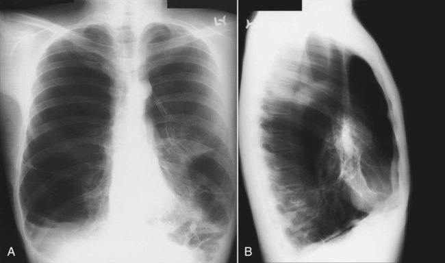
Assessment of lung volumes on a chest radiograph requires several observations. Rib counting is a popular method to assess lung volume. With a good inspiration, the sixth and sometimes the seventh anterior rib should project above the diaphragm. If more than seven anterior ribs are visible above the diaphragm, hyperinflation is present. Obstructive pulmonary disease is classically associated with increased lung volumes (hyperinflation). In patients with chronic obstructive pulmonary disease, there may also be an increase in the AP diameter of the chest, with associated enlargement of the retrosternal and retrocardiac airspaces and flattening of the hemidiaphragms. These all are secondary signs of pulmonary emphysema. The only primary signs of emphysema are loss or shifting of pulmonary vessel markings and the appearance of the walls of bullous airspaces (Figure 20-24).
 Rule of Thumb
Because radiographic signs of emphysema are apparent only with more advanced disease, the chest radiograph is generally considered insensitive for detecting obstructive lung disease. However, HRCT is far more sensitive and may show evidence of emphysema even when pulmonary function test results are normal.20 Figure 20-25 shows a case of upper lobe paraseptal emphysema, characterized by cysts on the pleural surface. A chest CT scan may prove useful to help define which patients may benefit from treatments such as lung volume reduction surgery.
Solitary Pulmonary Nodule
A solitary pulmonary nodule (SPN) is a parenchymal opacity smaller than 3 cm in diameter that is totally surrounded by aerated lung. One or two SPNs are encountered in every 1000 chest radiographs. SPNs are important to identify because they may be caused by lung cancer. The reported prevalence of malignancy in SPN ranges from 3% to 6% in large surveys of the general population. In patients with SPN who have surgical resection, 30% to 60% of the nodules are malignant.21
When first encountered, SPN should be assessed for features listed in Table 20-2 that may help establish a nonmalignant cause. The goal of imaging SPNs is to avoid resecting benign nodules, while encouraging surgical removal of all potentially curable cancers. The axial anatomic display of CT coupled with better density-discriminating powers make CT a favored tool for evaluating SPN. CT provides a detailed evaluation of the shape and edges of pulmonary nodules, in addition to helping to identify whether calcification is present and, if so, the pattern of its calcification (Figure 20-26).
TABLE 20-2
Features Useful in Distinguishing Benign from Malignant Solitary Pulmonary Nodules
| Feature | Favoring Malignant Nodule | Favoring Benign Nodule |
| Patient age | >40 years old | <40 years old |
| Smoking status | Current or former smoker | Lifetime nonsmoker |
| Size of nodule | >3 cm | <3 cm |
| Shape of nodule | Lobulated | Spherical |
| Margins of nodule | Spiculated | Well defined |
| If cavity | Thick-walled | Thin-walled |
| Doubling time* | 7-465 days | <7 or >465 days |
| Calcification | Rare, usually eccentric | Central, lamellar, popcorn |
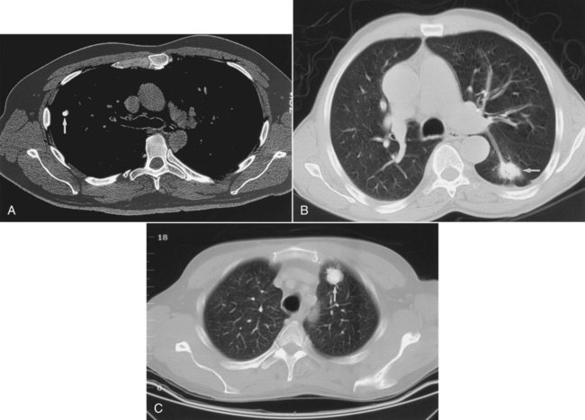
Central, or lamellar (swirls of concentric rings), calcification strongly suggests a benign cause of SPN or a granuloma. Eccentric (off-center), speckled, or amorphous calcification may be seen in cancers. A smooth-edged, round nodule more often is benign, whereas a lobulated or spiculated (having a spikelike appearance) edge is more likely to be a malignant nodule (see Figure 20-26). PET is often very helpful in evaluating SPNs. Nodules with greater than 1 cm diameter that are avid for the isotope used in PET (fluorodeoxyglucose) and “light up” on the scan generally are more likely to be malignant than nodules without uptake.
Mediastinum
The mediastinum consists of the heart, great vessels, trachea, and other soft tissue structures that lie between the lungs. The mediastinum is divided into three compartments: anterior, middle, and posterior. When a mediastinal abnormality has been found, determining the precise portion of the mediastinum that is affected helps determine possible causes. The mediastinal compartments are best defined on a lateral chest film (see Figure 20-3). A line extending from the diaphragm along the posterior margin of the heart and the anterior margin of the trachea to the neck divides the anterior mediastinum from the middle compartment. A second line traversing the vertebral bodies 1 cm behind their anterior margins and extending from the neck to the diaphragm divides the middle from the posterior compartment. Most mediastinal masses are visible on both front and lateral projections, and the specific location within the mediastinum offers the first clue to diagnosis.
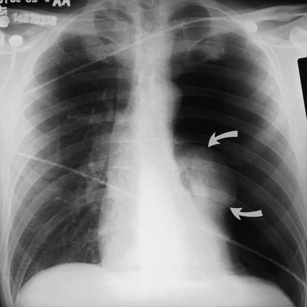
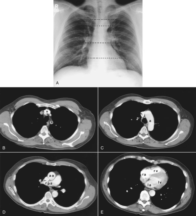
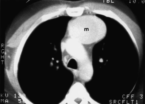
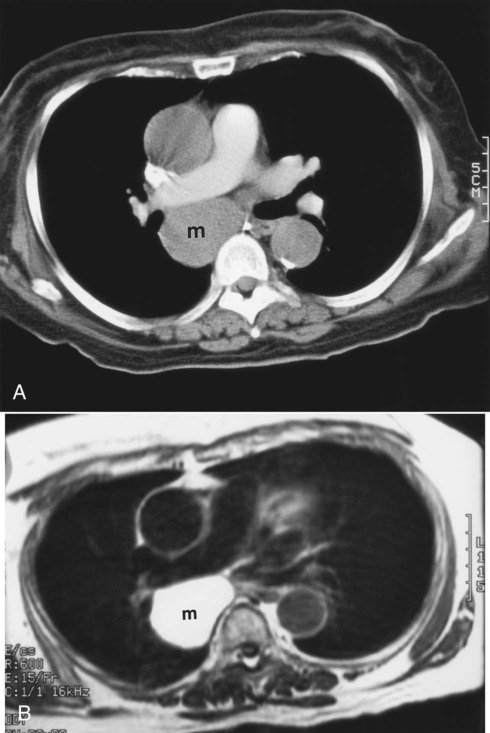
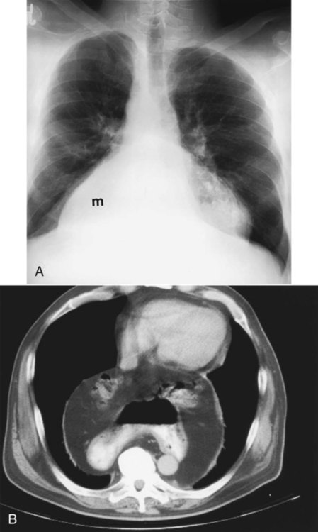
Table 20-3 lists the common causes of masses in the three mediastinal compartments. CT is the best type of imaging for assessing most mediastinal masses. Figure 20-27 shows the normal axial anatomic display on contrast-enhanced CT scan at the levels of the great vessels, aortic arch, carina, and cardiac chambers. The CT appearance of an anterior mediastinal mass (thymoma) is shown in Figure 20-28. Figure 20-29 shows a middle mediastinal mass (bronchogenic cyst) on both axial CT and MRI scans. A large hiatal hernia in the posterior mediastinum can easily be confused with a mass on the frontal chest film but is easily seen on CT in Figure 20-30.
TABLE 20-3
Mediastinal Abnormalities by Compartment
| Anterior Mediastinum | Middle Mediastinum | Posterior Mediastinum |
| Thyroid or parathyroid mass | Aortic aneurysm (ascending/arch) | Aortic aneurysm (descending) |
| Thymic lesions | Lymphadenopathy | Neurogenic tumors |
| Lymphoma | Bronchogenic cyst | Lymphoma |
| Pericardial cyst/fat pad | Tracheoesophageal masses | Neurenteric cyst |
| Teratoma | Hiatal hernia | Bochdalek hernia* |
| Morgagni hernia* | ||
| Ventricular aneurysm |
*Hernia in which the abdominal contents press through a gap in the diaphragm.
Pneumomediastinum
Pneumomediastinum, a form of barotrauma, may result from movement of air into the mediastinum, as may also be seen in cases of esophageal rupture (Figure 20-31). This condition usually occurs in the distal portion of the esophagus in patients who undergo procedures to stretch or dilate the esophagus. Chest trauma may cause rupture of a main bronchus, also allowing movement of air into the mediastinum. Rarely, air dissects down from the soft tissues of the neck after thyroid, parathyroid, or tonsillar surgery. Gas associated with a retrotonsillar abscess may also move down to the mediastinum through the fascial planes of the neck. Air that accumulates in the retroperitoneum may enter the mediastinum via openings in the diaphragm for the aorta or esophagus.
Catheters, Lines, and Tubes
Endotracheal Tube
Endotracheal tubes are radiopaque or have an opaque marker indicating the end of the tube. Radiographs are routinely obtained at the bedside after intubation to assess correct tube position. The radiograph shows the distal tip of the endotracheal tube and the carina.22 The position of the patient’s neck is important. The neck position usually is neutral, but the position of the tip of the endotracheal tube can vary with neck position. Specifically, the endotracheal tube position can move 4 cm toward the main carina as the neck moves from full extension (high position) to full neck flexion (low position), which is one-third the length of the average adult trachea. Goodman and Putman23 suggested that when the head and neck are in the neutral position, the endotracheal tube should be positioned in the midtrachea (5 to 7 cm from the carina). Placement below the thoracic inlet ensures that the tube is beyond the vocal cords (usually at C5-6). Figure 20-32 shows a malpositioned endotracheal tube in the right main stem bronchus.
 Rule of Thumb
Pulmonary Artery (Swan-Ganz) Catheter
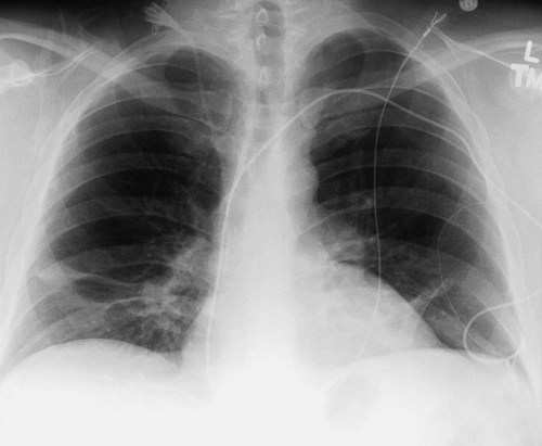
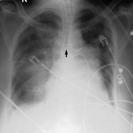
A Swan-Ganz catheter is used to measure hemodynamic and central pressure variables such as pulmonary artery occlusion pressure. Pulmonary artery catheters are placed at the bedside and ideally should reside in the proximal right or left main pulmonary arteries. They are floated into position using an inflatable balloon on the catheter tip. Because of this floating, they are placed in the right pulmonary artery more than 90% of the time. When measuring the so-called wedge or pulmonary artery occlusion pressure, the balloon is inflated, and the catheter moves out into a more peripheral vessel. As soon as the reading is accomplished, the balloon should be deflated, and the catheter should be pulled back to a central location. Persistent peripheral placement (i.e., when the catheter tip is far out in the lung parenchyma) can cause infarction of lung distal to the wedged catheter (Figure 20-33).
[/level-membership-for-pulmolory-and-respiratory-category][not-level-membership-for-pulmolory-and-respiratory-category]
Review of Thoracic Imaging
After reading this chapter you will be able to:
List the four tissue densities seen on a chest radiograph.
Define the terms radiolucent and radiopaque.
Describe how to evaluate the technical quality of a chest radiograph.
State the differences between a posteroanterior chest film and an anteroposterior chest film.
List the anatomic structures seen on a chest radiograph.
List the steps used to interpret thoracic imaging studies.
Identify the value of a computed tomography (CT) scan, high-resolution CT scan, and CT angiogram.
Describe the common radiographic abnormalities seen in the pleura, lung parenchyma, and mediastinum.
Overview of Plain Chest Radiograph
When to obtain a chest radiograph is ultimately the decision of the attending physician. However, the RT may be able to suggest that a chest x-ray should be obtained in certain circumstances, such as when a patient in the intensive care unit suddenly deteriorates for no apparent reason. The RT needs to be familiar with the common clinical indications for obtaining a chest radiograph (Box 20-1).
Approach to Reading a Plain Chest Radiograph
In broad terms, the steps in reviewing a chest film are as follows:
• Identify the name on the radiograph.
• Review the technique and quality of the film: Is the film well centered (i.e., the spinous processes are right in the middle of the trachea on a posteroanterior [PA] film), and is the amount of penetration of the beam adequate, too high (i.e., the lung parenchyma is too dark to see subtle changes), or too low (i.e., the lung parenchyma is too white, causing normal lung markings to appear abnormal)?
• Systematically review the anatomic structures on the chest film to assess their normality or abnormality.
Chest Radiograph Technique and Quality
Several technical factors should be routinely assessed when reading a chest film:
1. Is the film appropriately labeled?
2. Is the film PA with a lateral view, or is it an anteroposterior (AP) portable film?
3. Is the entire chest imaged on the film (i.e., are any structures cut off from the film)?
4. Was the patient properly positioned for the film?
5. Were the optimal settings for the x-ray beam selected when the film was taken (the term used is penetration, which is similar to exposure on camera film)?
Patient rotation can make interpretation more difficult by projecting midline structures (e.g., the trachea) to the right or left. The observer can assess for rotation by comparing anterior structures such as the medial (toward the middle) ends of the clavicles with a posterior structure such as the spinous process (midline structure of the spine). In a perfectly positioned or aligned chest film, the spinous process should be seen midway between the medial ends of the clavicles and in the middle of the tracheal air column (Figure 20-1). Patient rotation makes the mediastinum appear unusually wide and obscures or distorts the appearance of the pulmonary arteries as they emerge from the mediastinum into the lung parenchyma.
Anatomic Structures Seen on a Chest Radiograph
After the RT has reviewed the technical aspects of the chest radiograph, it is time to review the anatomic findings in the film. The main structures imaged on a routine chest radiograph are listed next and illustrated in Figure 20-2:
1. Bones (e.g., ribs, clavicles, scapulae, vertebrae)
2. Soft tissues (e.g., tissues of the chest wall, upper abdomen, lymph nodes)
3. Lungs (including the trachea, bronchi, and lung tissue or parenchyma)
4. Pleura (membranous coverings of the lung, including the visceral pleura [the part attached to the lungs] and the parietal pleura [the part lining the inside of the chest wall]; although normally occupied by only a small amount of fluid, the space between the parietal and visceral pleura is called the pleural space)
5. Heart, great vessels, and mediastinum (i.e., the tissues between the two lungs in the center of the chest, bordered by the sternum and the vertebral column in the AP dimension and by the thoracic inlet [where the trachea enters the thorax] and the diaphragm in the cephalocaudal direction)
Review of the lung edge on both frontal and lateral films discloses any pleural abnormalities, such as fluid in the pleural space (e.g., hydrothorax, hemothorax [blood in the pleural space]) and air in the pleural space (pneumothorax). Evaluation of the mediastinum should include assessment of heart size. In the PA projection, the diameter of the heart shadow should not exceed one-half the diameter of the chest. An enlarged heart may occur with congestive heart failure or with a large pericardial effusion (accumulation of fluid within the space that surrounds the heart encased within the pericardium). The lateral contours of the mediastinum should correspond to normal anatomic structures as outlined in Figure 20-3.
Advanced Chest Imaging Techniques
Computed Tomography of the Chest
Computed Tomography Angiography
The rapid scanning that can be performed on helical CT scanners has made CT angiography possible. To perform CT angiography, a large amount of contrast dye is injected into the patient’s vein. The CT technician monitors the movement of contrast material so the scan can be started when the contrast material has entered the area to be studied. CT angiography of the chest has been used for years to identify pulmonary thromboemboli (Figure 20-4).1 More recently, CT angiography of the coronary artery has been evaluated; this seems to provide an alternative to routine coronary angiography in many patients.
Three-Dimensional Reconstruction
The imaging processing capabilities of modern CT scanners allow reconstruction of the chest in any direction and production of three-dimensional representations of some areas of the body (Figure 20-5). The term virtual bronchoscopy is used when these reconstructions simulate the view of the airways that a physician would have during bronchoscopy.
