Chapter 101 Principles and Techniques of Vitreoretinal Surgery
Vitreoretinal surgical anatomy
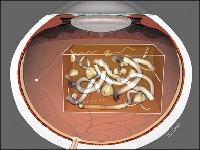
The vitreous can be considered as a three-dimensional matrix of collagen fibers and hyaluronic acid gel (Fig. 101.1). In the normal state, the outer surface of the vitreous is in contact with the retina, pars plana, and ciliary body in a roughly spherical shape with an anterior facet for the lens. Disease-induced RPE and glial cell migration, attachment of cells to the extracellular matrix and hypocellular contraction of the collagen matrix take place with the majority of the relevant changes occurring at the cortex surface. The anterior vitreous cortex (AVC) is contiguous with the posterior vitreous cortex (PVC) and, for the most part, is nonfenestrated.
Mechanics of vitreoretinal surgery
Peeling
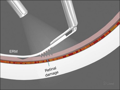
Force along the axis of a collagen fiber bundle causes non-elastic collagen fibers to slightly stretch and ultimately to fail. Damage to attached structures is a function of the number of fibers and the strength of the attachment and the substrate. Membrane peeling requires force perpendicular and tangential to the retina, which causes failure of the attachment at the vitreoretinal interface by elongation. Because dense, highly adherent membranes such as those associated with diabetic traction retinal detachments are approximately 100 times stronger than the retina, retina surface defects or retinal breaks usually occur before removal of the membrane occurs (Fig. 101.2). For this reason, membrane peeling is inappropriate in diabetic traction retinal detachment cases.
Shear
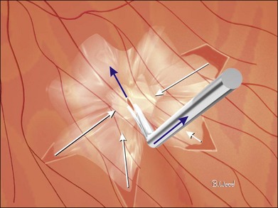
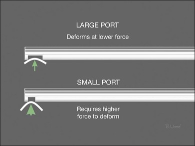
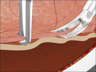
Shear cutting occurs when force is applied along two opposing parallel edges moving past each other. Vitreous cutters and scissors use shearing to cut tissue. Inclusive shears such as a vitreous cutter prevent the push-out force that occurs as exclusive shears (scissors) close (Fig. 101.3), pushing the tissue away from the fulcrum, but require elastic deformation of tissue into the port caused by transport pressure gradient (Fig. 101.4).
Infusion system management
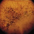
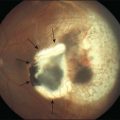
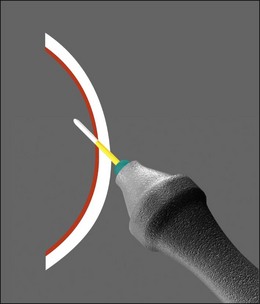
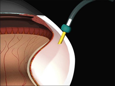
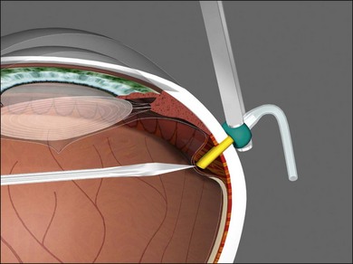
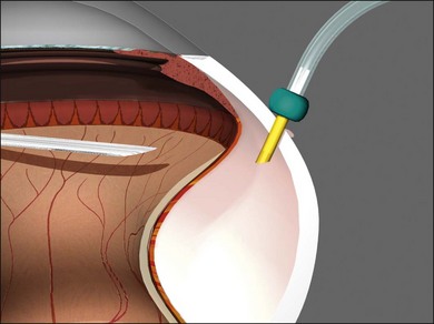
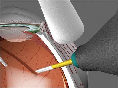
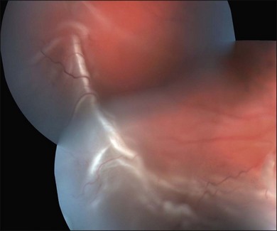
Vitrectomy surgeons have occasionally experienced excessively low intraocular pressure (IOP) during vitreoretinal surgery throughout the history of vitreoretinal surgery. Gravity-fed infusion systems were simplistic and could only cause low intraocular pressure if the bottle was too low or the infusion fluid was depleted. Sutured 20-gauge (G) vitrectomy resulted in low intraoperative IOP if the cannula was initially positioned into the suprachoroidal space without surgeon recognition or displaced intraoperatively thereby causing suprachoroidal infusion. Digital display of infusion driven by an air pressure source in the machine created the false impression that IOP was controlled when in fact as much as 25 mmHg of difference existed between infusion pressure and IOP with typical flow rates during core vitrectomy and fragmenter use. The fragmenter lumen, unlike the vitreous cutter is not obstructed by an inner needle or port opening and closing. Low intraoperative IOP is prevented by using a sufficient infusion pressure to compensate for infusion line and cannula resistance-based losses. Ohm’s law of fluidic resistance; pressure = flow × resistance, explains pressure drop in the infusion system during flow. There are many causes of excessively low intraocular pressure during vitrectomy; each of these will be discussed. Inadvertent suprachoroidal infusion is a relatively common cause of low pressure as well as other more serious complications during vitrectomy with 23G and 25G surgery as well as the 20G sutured systems used for over three decades. Sutureless 25G vitrectomy initially utilized straight-in trocar cannula trajectories to produce sclerotomies perpendicular to the sclera. When 23G, sutureless surgery was introduced subsequently, oblique trocar-cannula entry was utilized in order to construct a scleral tunnel to reduce wound leakage. Initially, surgeons used a two-plane approach; the initial trocar-cannula insertion segment was approximately 30° relative to the sclera and the second segment trajectory perpendicular to the sclera. Some surgeons even believed that a biplanar incision was constructed, although this is not true because the scleral tunnel was created before changing the trajectory. More recently, surgeons using both 23G and 25G systems have switched to oblique entry in order to create a long scleral tunnel1–3; unfortunately some surgeons use excessively steep angles (5–10°). Although near tangential entry creates a long scleral tunnel; it increases the chances of infusing into the suprachoroidal or subretinal space (Fig. 101.5). If the cannula is in the suprachoroidal space, the peripheral choroid, which is not observed by the surgeon, expands early in the case allowing infusion without hypotony, later the choroid can no longer expand and infusion becomes limited, alerting the surgeon to the problem (Fig. 101.6). Thinking that hypotony caused a choroidal effusion leads to incorrect management. A single plane, 20–30° trajectory is better compromise between the benefits of a long scleral tunnel and the catastrophe of suprachoroidal infusion. Inspecting the infusion cannula with the operating microscope after insertion and before initiating infusion was standard practice with sutured 20G vitrectomy. Many surgeons have discontinued this practice since 23/25G sutureless vitrectomy began; clearly the crucial step of observing the tip of the infusion cannula must not be omitted. It is best practice to insert the infusion port in the cannula with the infusion running to prevent bubbles followed by immediate inspection of the tip of the infusion cannula. The naked eye and endoilluminator provide insufficient magnification to make the determination that the cannula has penetrated the choroid and non-pigmented pars plana epithelium; microscope visualization is essential. Adhesively fastening the infusion cannula tubing and associated stopcock(s) and connectors to the drape is imperative to prevent traction on the infusion cannula and the eye. Unrecognized pulling on the tubing by the assistant or surgeon can easily cause the cannula to partially pull out causing a suprachoroidal infusion. Adhesively fastening the infusion cannula tubing to the drape with eye in the primary position with a short tubing loop can result in a suprachoroidal infusion when the eye is rotated to view the periphery creating tension on the cannula. Scleral depression is another cause of inadvertent suprachoroidal infusion by causing torque on the cannula as the eye is rotated by the depressor. In addition, scleral depression can force blood clots, dense scar tissue, peripheral vitreous, or silicone oil into the infusion cannula and tubing, effectively plugging it, giving the false impression of infusion system failure. Placing the infusion cannula too close to the lower lid rather than just inferior to the horizontal meridian is a common cause of suprachoroidal infusion created when the eye is rotated down to visualize the inferior periphery and the cannula is rotated into the suprachoroidal space. Kinking of the more flexible silicone tubing terminal segment of the infusion cannula can be caused by the surgeon or assistant accidentally pulling on the tubing. This problem is exacerbated by using excessively low infusion pressure settings (10–25 mmHg) insufficient to straighten out the tubing kink. The author has always used 45 mmHg except when operating on children or patients with very low systemic blood pressure, typically under general anesthesia. Some surgeons have recently advocated using infusion settings of 10–20 mmHg because of a completely unfounded belief that occult ischemia is common during vitrectomy. Using infusion settings of 10–20 mmHg causes miosis, bleeding, and corneal astigmatism from contact lens pressure on the cornea and instrument forces on the sclerotomies as well as scleral infolding often mistakenly thought to be choroidals. Kinking as well as multiple bubbles in the infusion line increase resistance to flow and cause pressure drop ultimately resulting in excessively low IOP. Surgeon remediation of intraoperative low IOP should be systematic; the first step is to inspect the cannula with the microscope to make sure it extends all the way through the choroid and non-pigmented ciliary epithelium. If not, a 25G MVR blade can be used to incise the tissue covering the cannula while pressing the cannula into the eye with smooth forceps (Fig. 101.7). Another option is to move the infusion system port to the supranasal cannula. The infusion tubing should be examined for kinking or inadvertent disconnection. Kinking is most common when excessively low infusion pressure settings are used and the tubing bends at the fluid–air stopcock/valve. If a suprachoroidal infusion occurs, infusion through a cannula with a 25G needle (if 25G surgery) into the middle of the eye will compress the choroid against the sclera and cause the suprachoroidal fluid to disappear often via egress around the cannulas (Fig. 101.8). Cut down drainage is never necessary. If choroidals are present at the inception of surgery, a 6 mm instead of 4 mm cannula can be used and/or infusion initiated with a 25G needle as described above.
Vitreous cutter considerations
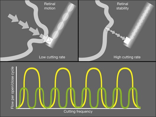
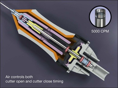
All current vitreous cutters utilize suction and inclusive shearing. Ideal tissue cutting is defined as that producing zero displacement of the tissue to be removed and no vitreoretinal traction. It is safest to use the lowest suction force sufficient to imbricate tissue or vitreous into the cutter port. High cutting rates (≥5000 cuts/minute) increase port-based flow limiting and thereby decrease pulsatile fluid flow and pulsatile vitreoretinal traction (Fig. 101.9). Port-based flow limiting via high cutting rates also limits fluid surge after sudden elastic deformation of dense ERM, scar tissue or lens material through the port. Dual actuation eliminates the spring, which facilitates higher cutting rates and enables duty cycle control (Fig. 101.10). In summary, using the highest available cutting rate is the best approach for all tasks and all cases unless all the vitreous has been removed first.
Microscope requirements
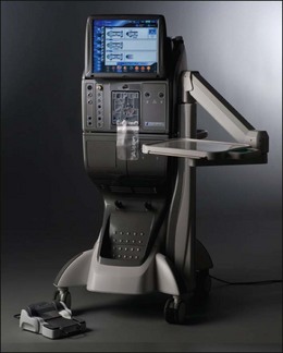
All power and control sources for surgical tools should be integrated into a single system for greater efficiency. Advanced vitreoretinal surgery systems have a unified human–machine interface combining all surgical functions into an integrated system (Fig. 101.11). Illumination, diathermy, and infusion are referred to as global functions and are always available. Infusion is best controlled by digital, sensor-based, pressurized infusion systems.
Surgical steps
Transconjunctival, small gauge vitrectomy
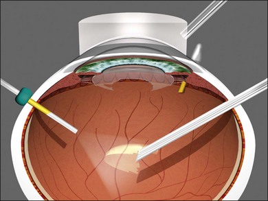
Transconjunctival, sutureless 23/25/27G vitrectomy systems have improved to the point that in general, there is no longer a need for 20G vitrectomy; referring to 20G vitrectomy as the “gold standard” is, in the author’s opinion, now arcane. The advantages of 23/25/27G are improved safety because of fewer iatrogenic retinal breaks, reduced operating times, less patient discomfort, and faster visual improvement.4–6 A single 20G sclerotomy is required to remove intraocular foreign bodies and for a fragmenter to remove dense lens material (Fig. 101.12).
Sclerotomies
Conjunctival displacement ensures that the conjunctival trocar-cannula wound is not overlying the scleral trocar-cannula wound (Fig. 101.13). Conjunctival displacement is essential for the transconjunctival sutureless technique, to provide containment of vitreous wick as well as prevent access of tear film to the sclerotomies, thereby reducing endophthalmitis risk.
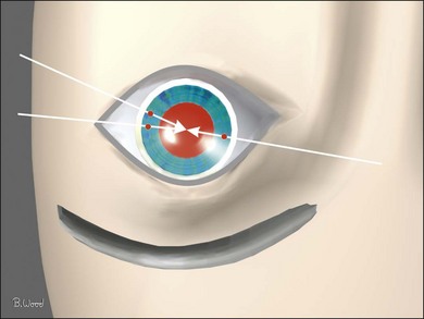
There is no rule that sclerotomies should be placed at certain hours of the clock or at the borders of the rectus muscles; they should be located to avoid conjunctival scars, filtering blebs and regions of abnormal pars plana, as well as facilitate the greatest possible solid angle intraocular access (Fig. 101.14). The inferotemporal sclerotomy should be located just below the horizontal meridian to reduce the risk of bumping the lower lid when rotating the eye to view the inferior retina. The superonasal sclerotomy should be located on a virtual line from the lowest point of the bridge of the nose to the pupillary axis. The supertemporal sclerotomy should be located on a virtual line from the lowest point of the supraorbital rim to the pupillary axis; the cannula hub will then be immediately adjacent to the inferotemporal cannula hub. More anterior or nonstandard locations are required in cases of congenital or pathologic abnormalities of the pars plana.
Vitreous removal
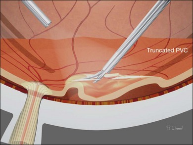
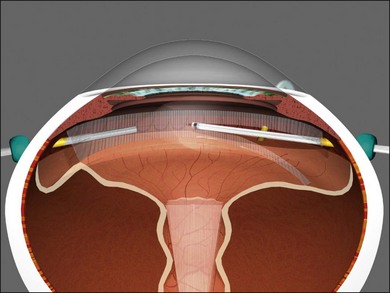
Conventional algorithms have stressed the sequence: core vitrectomy followed by posterior vitreous detachment (PVD) creation if PVD is not present, then so-called peripheral vitreous shaving and finally management of epiretinal membranes. Cutting technology, surgical techniques and understanding of pathoanatomy have improved to the point that a linear algorithm no longer suffices; therefore, each algorithm should be selected according to case-specific pathoanatomy. If the AVC is semi-opaque, opaque, or taut, it should be removed first. If it is clear and the lens is to be left in place, it should be retained unless there is an element of anterior loop traction (anterior proliferative vitreoretinopathy) or compartmentalization requiring removal (see Lens management, below). In the majority of cases, the “core” vitreous requires no specific attention, and the algorithm should proceed to the decision about whether to truncate the PVC or to delaminate ERM first. If the PVC is opaque or semiopaque, it usually requires truncation before the ERM can be peeled or delaminated (Fig. 101.15). When there is a partial PVD and the ERM is continuous with sections of the PVC, delamination should precede PVC truncation (Fig. 101.16).
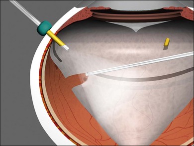
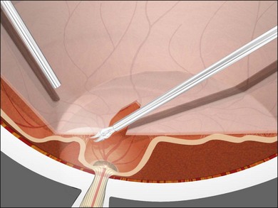
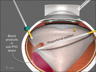
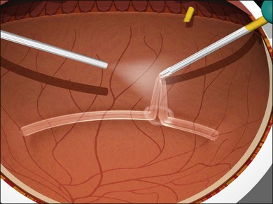
If sub-PVC blood products are encountered while PVC truncation is under way, a soft-tip cannula or vitreous cutter with cutting deactivated should be used to remove blood, this is referred to as extrusion (Fig. 101.17). If, in the process of PVC truncation, regions of PVC are stretched between areas of ERM, they can be sectioned with the cutter only if it can be done without undue traction on the retina. Curved scissors should be used to segment these sections of the PVC if there is concern about iatrogenic retinal breaks in atrophic, elevated retina (Fig. 101.18).
Anterior loop traction (radial fibers) is a significant feature of anterior proliferative vitreoretinopathy (PVR), some trauma cases, and anterior hyaloidal fibrovascular proliferation (retrolenticular neovascularization) in severe proliferative diabetic retinopathy (PDR) cases. Anterior cortical fibers are made taut by hypocellular vitreous contraction extending in the anteroposterior direction from the vitreous base to the pars plana, ciliary body, and even to the posterior iris surface. They can be present typically inferiorly in PVR cases, or in severe cases, this pathoanatomy can extend for 360°. Anterior loop traction is to be differentiated from the “skirt” that is left after core vitrectomy. Anterior loop traction can be visualized with contact-based wide-angle viewing, scleral depression by the surgeon using chandelier illumination, or scleral depression by the assistant. Wide-angle viewing systems are essential for viewing the periphery; contact-based wide-angle viewing provides 10° greater field of view than non-contact systems, eliminates all corneal asphericity and requires less ocular rotation. Scleral depression is very effective but requires a skilled assistant or chandelier illumination, which reduces the ability to visualize clear vitreous. Anterior loop traction can usually be resected with a 23/25/27G vitreous cutter (Fig. 101.19).
Lens management
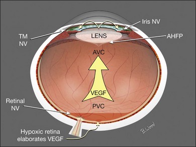
In addition to its normal optical function for the patient, the lens affects the vitrectomy-based management of retinal detachment. Cells, as well as cytokines, proteins, and inflammatory components, are retained in the vitreous cavity and thus are exposed to the retina longer in the phakic and pseudophakic eye. In cases of severe PVR, extensive giant breaks, severe uveitis, and severe trauma, it may be advantageous to remove the lens to accomplish decompartmentalization of the eye (Fig. 101.20). Aphakia also permits better dissection of the anterior vitreous, eliminates concern about subsequent cataract surgery, improves visualization, and facilitates exchanges. In PDR, there is a trade-off in that the presence of the lens greatly reduces neovascular glaucoma, but facilitates anterior fibrovascular proliferation (retrolenticular neovascularization) and greatly prolongs the retention time of postoperative hemorrhage. Lens removal in conjunction with diabetic vitrectomy or retinal detachment is best managed with phacovitrectomy and introduction of an acrylic posterior chamber lens.
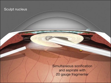
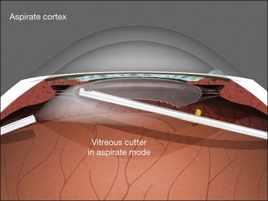
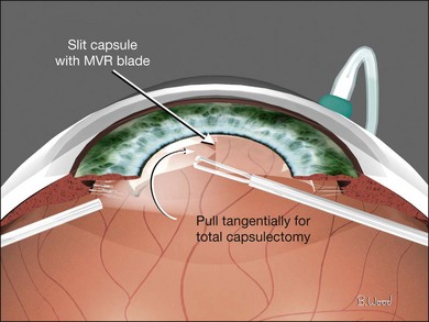
Endocapsular lensectomy is an efficient and safe method of lens removal if intraocular lens (IOL) implantation is not planned. The first step is placement and verification of the infusion cannula insertion through the choroid and non-pigmented pars plana epithelium using the operating microscope, not the naked eye. Anterior vitrectomy should be performed before lensectomy to prevent traction on the retina from the fragmenter. The cutter should then be used to make a circular rhexis in the posterior capsule. Hydrodissection and delineation should be performed with a 27–30G blunt cannula. A fluid wave should be seen under the anterior lens capsule (Fig. 101.21). An assistant-held syringe or a machine-controlled fluid injector connected to a short length of tubing facilitates this step. Sculpting of the epinucleus, nucleus, and inner cortex with the fragmenter at moderate power levels is the next step (Fig. 101.22). Simultaneous sonification and aspiration using a 20G fragmenter is better than intermittent suction followed by sonification without aspiration, because it is less likely to cause scleral burns. The cortex should then be aspirated with the vitreous cutter in suction-only mode (Fig. 101.23). The cutter can then be used in cutting mode after the cortex has been displaced from the capsular bag. If severe miosis occurs, scleral depression or injection of 1 : 10 000 epinephrine (adrenaline) without preservative will facilitate the required removal of all peripheral cortex. Proportional (linear) suction should be used with typical suction levels of 100–150 mmHg while in the capsular bag. A capsulotomy to facilitate forceps removal of the capsule should be made with the MVR blade or cutter after all cortex is removed if lens implantation is not planned. The entire capsule should then be removed with the end-grasping forceps using a circular, zonular rhexis motion (Fig. 101.24). Removal of the complete capsule prevents the inflammation and peripheral proliferation associated with the retention of lens material as well as fibrosis-based closure of peripheral iridectomies.
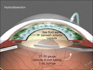
Fig. 101.21 A fluid wave should be seen under the anterior capsule during hydrodissection and delineation.
Epiretinal membrane management
Disposable, 25G or 23G, end-grasping ILM forceps are the author’s preferred instruments for peeling PVR membranes, as well as epimacular membranes and internal limiting membrane peeling (Fig. 101.25). End-grasping forceps membrane peeling eliminates the need for pics, membrane scrapers, and MVR blades, all of which can damage the retinal surface.
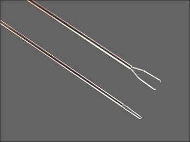
Fig. 101.25 ILM forceps are ideal for both epimacular membrane and internal limiting membrane peeling.
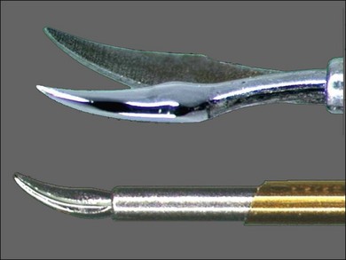
The preferred tool for delamination and access segmentation is 25G or 23G curved scissors (Fig. 101.26). Because the radius of curvature is similar to the retinal contour, the chance of making iatrogenic retinal breaks is reduced compared with the 135° (“right-angle”) scissors. Curved scissors are also preferred over vertical scissors for segmentation because blade thickness is much less than blade width (Fig. 101.27); iatrogenic retinal breaks are less likely when the bottom blade is inserted in the potential space between ERM and retina. In addition, transition from access segmentation to delamination does not require tool exchange, only small-angle tool rotation to place both blades under the ERM and begin delamination.
Management of subretinal proliferation
Subretinal proliferation can be placoid, band-like, or annular in configuration (Fig. 101.28). Because the biologic behavior seems to be less likely to result in reproliferation, subretinal membrane removal is dictated by geometric considerations. If the retina cannot be reattached with an undistorted macula due to subretinal proliferation, subretinal surgery is indicated.
Subretinal surgery can be categorized as peeling or scissors segmentation. If a retinal break is appropriately positioned, forceps can be passed through the break and used to grasp and remove long dendrites with a sequential re-grasping technique (Fig. 101.29). If a convenient break is not present, punch-through retinotomy with the forceps is the preferred technique (Fig. 101.30). If the membrane is placoid, forceps removal should be used. Occasionally, subretinal bands are fibrovascular and require scissors segmentation rather than forceps removal.
Extrusion techniques
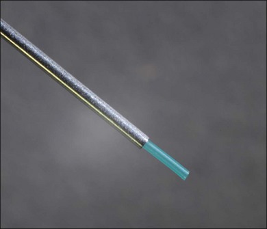
Soft-tip cannulas (Fig. 101.31) can be used to remove material from the eye using foot pedal controlled machine-driven aspiration; this is called extrusion. Soft-tip 23/25G cannulas with low suction levels are ideal for removing free blood products, PFO (perfluoro-n-octane), oil droplets, or small pieces of lens material from the retinal surface or vitreous cavity after the vitreous is removed with the cutter. Extrusion is always preferable to using the flute cannula because inadvertent tip movement due to covering the egress hole on the handle, and extrusion provides more precise aspiration control as well as foot pedal controlled precision reflux.
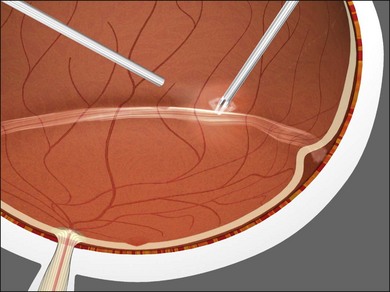
Flexible soft-tip cannulas are preferred over rigid cannulas for internal drainage of subretinal fluid (SRF) because they can be angulated into the subretinal space (Fig. 101.32) and are less likely to damage the choroid and cause bleeding with patient movement or suboptimal positioning due to poor visualization. The algorithm for internal drainage of SRF begins with drainage, then fluid–air exchange with continued or repetitive internal drainage of SRF. If fluid–air exchange is done before internal drainage of subretinal fluid, the SRF is forced posteriorly, creating the need for drainage retinotomy and potentially detaching an attached macula.
Interfacial surface tension management
Air (gas) interface with aqueous (72 dyne/cm2) provides greater interfacial surface tension than the silicone–aqueous interface (40 dyne/cm2) (Fig. 101.33). Viscoelastics and lipoproteins from blood or inflammation lower the interfacial tension of the silicone–aqueous interface causing emulsification.
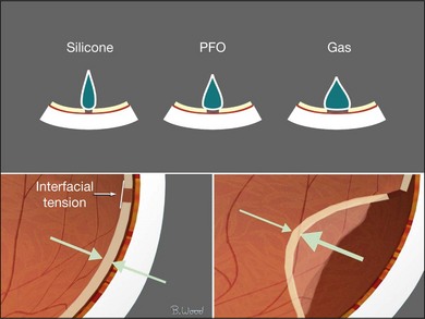
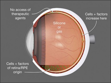
Silicones and gases may contribute to reproliferation by sequestering cytokines, proteins, and cells at the retinal surface (Fig. 101.34). The best silicone oils are those with the highest electrical resistance, lowest vapor pressure, and 1000 cSt (centi-Stokes) viscosity. There is no scientific evidence that 5000 cSt oil has lower emulsification rates than 1000 cSt and 5000 cSt oil takes five times as long to inject and remove as 1000 cSt.
An inferior peripheral iridectomy in aphakic eyes or eyes with decentered intraocular lenses and capsular defects allows aqueous to enter the anterior chamber from below and reduces the chance of silicone oil contact with the cornea. Fewer than 5% of long-term silicone cases develop corneal problems because of the iridectomy and higher-quality silicone oil available today. Emulsification glaucoma is relatively uncommon if proper precautions are taken. With the improvements in silicone oil, the incidence of emulsification glaucoma is now less than 20%, as previously reported.7
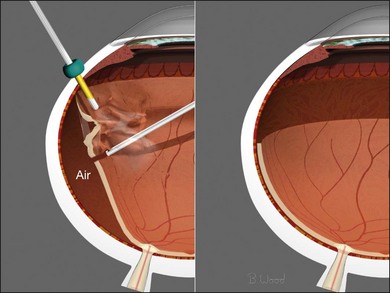
Fluid–air exchange
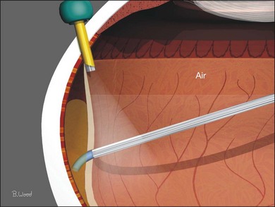
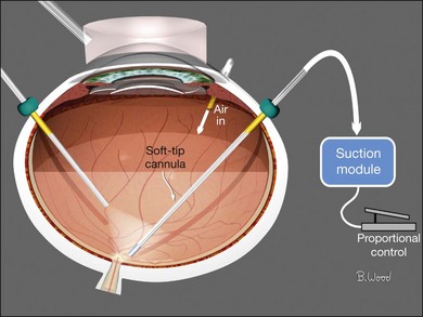
Air, for surface tension management, should be injected through the infusion cannula while simultaneously removing infusion fluid and SRF (Fig. 101.35), as described earlier (proportional suction, extrusion). Constant-pressure air pumps control intraocular pressure, are non-pulsatile, and can provide large flow rates to compensate for wound leaks. Incremental retinectomy and further vitreoretinal traction removal, forceps membrane peeling, segmentation or delamination can be performed under air if persistent traction is identified.8–10
Air–gas exchange
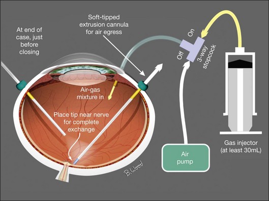
If a long-acting gas is chosen to maintain surface tension until retinopexy “seals” retinal defects, it should be injected in an isoexpansive concentration (25% SF6 or 18% C3F8) through the infusion cannula after fluid–air exchange and endolaser retinopexy has been completed (Fig. 101.36).11–18 The air is aspirated with constant low suction near the optic nerve to ensure complete exchange and accurate gas concentration. Injecting aliquots of gas into an air-filled eye provides poor control of gas concentration and subsequent bubble size because of unknown ocular volume. This technique increase the likelihood of excessive intraocular pressure potentially resulting in central artery occlusion or insufficient gas fills.
Liquid perfluorocarbon
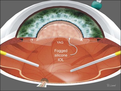
Liquid perfluorocarbon such as perfluoro-n-octane (PFO) is essential for repositioning giant retinal breaks and can be used for removal of subretinal fluid as well as stabilization of the retina to offset membrane peeling forces (Fig. 101.37).19–21 Fogging of the posterior surface of intraocular lenses occurs because the room temperature infusion fluid cools the IOL and the infused air is saturated with water vapor (Fig. 101.38). A capsule defect as well as discontinuity in anterior vitreous cortex is necessary for fogging to occur. Fogging can occur with polymethylmethacrylate (PMMA) and acrylic IOLs, although it is more common with silicone IOLs because of higher posterior capsule opacification (PCO) rates and greater thermal mass. If fogging occurs, the best practice is to return to BSS infusion, remove the air, reattach the retina with PFO and treat all retinal breaks with endolaser before performing PFO–gas exchange with isoexpansive SF6 or C3F8. PFO can be used in all retinal detachment cases but fluid–air exchange and internal drainage of subretinal fluid is effective and does not add cost. PFO should be used with caution in PVR cases because of the not uncommon occurrence of subfoveal PFO due to retinal breaks combined with rigid retina.
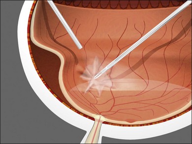
Fig. 101.37 PFO (perfluoro-n-octane) can be used to stabilize the retina and offset membrane peeling forces.
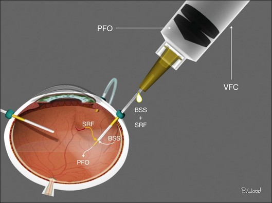
PFO should be injected under direct visualization by first injecting a small bubble at the optic nerve head with a 23G or preferably 25G dual-bore cannula. This bubble is enlarged by injecting, using a power injector with 10 psi injection pressure withdrawing the dual-bore cannula during the injection maintaining contact between the tip and the top of the PFO bubble. The proximal fluid egress port always stays above the PFO to avoid loss of PFO but allows fluid egress and a normotensive process (Fig. 101.39). PFO–air exchange in non-giant break cases is the inverse; the soft-tip cannula is always positioned at the fluid–PFO interface and advanced posteriorly so all the fluid is removed and replaced with air before PFO is removed.
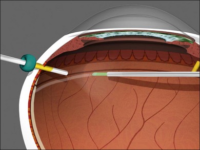
Air–silicone exchange
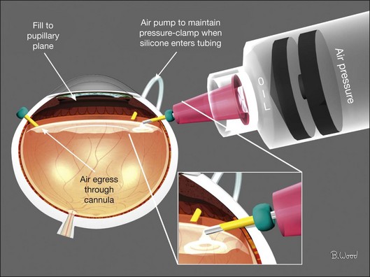
Because air has a higher interfacial tension than silicone oil, fluid–air exchange with internal drainage of SRF to reattach the retina should precede silicone infusion. Silicone should be injected with a pressure-controlled power injector through a short 23/25G straight cannula through the superotemporal cannula; not through the infusion cannula (Fig. 101.40). The air will egress through the open superonasal cannula until the silicone oil reaches the pupillary plane. Viscoelastics should be used to reform the anterior chamber if it becomes flat or if oil enters the anterior chamber.
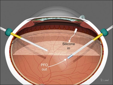
Perfluorocarbon–silicone oil exchange
Direct perfluorocarbon–silicone exchange is preferred over an intermediate step of fluid–air exchange followed by air–perfluorocarbon exchange in giant retinal break cases. The rationale for this approach is reduced chance of posterior slippage of the giant break. The goal is a full PFO fill and elimination of all subretinal fluid, infusion fluid and liquid vitreous. The soft-tip cannula is used to remove PFO as the power injector is used to inject oil through a special infusion cannula (Fig. 101.41). If a standard cannula is used for oil injection, each of the surgeon’s hands are in use therefore requiring a chandelier for illumination.
Retinectomy
Retinectomy should be performed in conjunction with fluid–air exchange and internal drainage of SRF (Fig. 101.42) (see also Chapter 108, Retinotomies and retinectomies). If subretinal air appears as internal drainage of SRF is slowly proceeding, the subretinal air location indicates residual retinal traction. Further vitrectomy, forceps membrane peeling, scissors segmentation/delamination, subretinal surgery, or retinectomy is required to achieve reattachment. Retinectomy should proceed incrementally with the vitreous cutter until the retina is reattached. Retinectomy performed under fluid is more difficult and may result in excessive or insufficient retinectomy. Large vessels should be precoagulated with bipolar diathermy.
Retinopexy
All forms of retinopexy create tissue destruction and reproliferation and therefore should be used as little as possible. Continuous (painting) laser endophotocoagulation is preferable to rows of spots because it results in more uniform tissue destruction and greater tensile strength (Fig. 101.43). Panretinal photocoagulation should only be used for neovascular retinopathies, never for PVR. Cryopexy causes more proliferation than laser or diathermy, and in my opinion, it should be avoided in vitrectomy surgery.
1 Rizzo S, Genovesi-Ebert F, Vento A, et al. Modified incision in 25-gauge vitrectomy in the creation of a tunneled airtight sclerotomy: An ultrabiomicroscopic study. Graefes Arch Clin Exp Ophthalmol. 2007;245:1281–1288.
2 Inoue M, Shinoda K, Shinoda H, et al. Two-step oblique incision during 25-gauge vitrectomy reduces incidence of postoperative hypotony. Clin Experiment Ophthalmol. 2007;35:693–696.
3 López-Guajardo L, Vleming-Pinilla E, Pareja-Esteban J, et al. Ultrasound biomicroscopy study of direct and oblique 25-gauge vitrectomy sclerotomies. Am J Ophthalmol. 2007;143:881–883.
4 Asheesh T, Shah GK, Fang A. Visual outcomes with 23-gauge transconjunctival sutureless vitrectomy. Retina. 2008;28:258–262.
5 Fujii GY, De Juan E, Jr., Humayun MS, et al. A new 25-gauge instrument system for transconjunctival sutureless vitrectomy surgery. Ophthalmology. 2002;109:1807–1813. [Erratum in: Ophthalmology 2003;110:9.]
6 Lakhanpal RR, Humayun MS, de Juan E, Jr., et al. Outcomes of 140 consecutive cases of 25-gauge transconjunctival surgery for posterior segment disease. Ophthalmology. 2005;112:817–824.
7 Barr CC, Lai MY, Lean JS, et al. Postoperative intraocular pressure abnormalities in the Silicone Study. Silicone Study Report 4. Ophthalmology. 1993;100:1629–1635.
8 Charles S. Fluid–gas exchange in the vitreous cavity. Ocutome Newslett. 1977;2:1.
9 Charles S. Controlled drainage of subretinal and choroidal fluid. Retina. 1985;5:233.
10 McCuen BW, Bessler M, Hickingbotham D, et al. Automated fluid–gas exchange. Am J Ophthalmol. 1983;95:717.
11 Abrams GW, Edelhauser HF, Aaberg TM, et al. Dynamics of intravitreal sulfur hexafluoride gas. Invest Ophthalmol. 1974;13:863–868.
12 Fineberg E, Machemer R, Sullivan P. SF6 for retinal detachment surgery, a preliminary report. Mod Probl Ophthalmol. 1974;12:173.
13 Fineberg E, Machemer R, Sullivan P, et al. Sulfur hexafluoride in owl monkey vitreous cavity. Am J Ophthalmol. 1975;79:67.
14 Chang S, Lincoff H, Coleman J, et al. Perfluorocarbon gases in vitreous surgery. Ophthalmology. 1985;92:651.
15 Lincoff A, Haft D, Liggett P, et al. Intravitreal expansion of perfluorocarbon bubbles. Arch Ophthalmol. 1980;98:1646.
16 Lincoff H, Coleman J, Kreissig J, et al. The perfluorocarbon gases in the treatment of retinal detachment. Am Acad Ophthalmol. 1983;90:546.
17 Lincoff H, Mardirossian J, Lincoff A, et al. Intravitreal longevity of three perfluorocarbon gases. Arch Ophthalmol. 1980;98:1610.
18 Aaberg TM, Abrams GW, Edelhauser HF. Intraocular sulfur hexafluoride: experimental and clinical correlation. International Symposium on New and Controversial Aspects of Vitreoretinal Surgery, Texas Medical Center, Houston, Texas. St Louis: Mosby; 1977. p. 393–7
19 Chang S, Ozmert E, Zimmerman NJ. Intraoperative perfluorocarbon liquids in the management of proliferative vitreoretinopathy. Am J Ophthalmol. 1988;106:668–674.
20 Chang S, Reppucci V, Zimmerman NJ, et al. Perfluorocarbon liquids in the management of traumatic retinal detachments. Ophthalmology. 1989;96:785–791.
21 Chang S, Lincoff H, Zimmerman NJ, et al. Giant retinal tears. surgical techniques and results using perfluorocarbon liquids. Arch Ophthalmol. 1989;107:761–766.