[level-membership-for-anesthesiology-category]
Pain management and regional anaesthesia
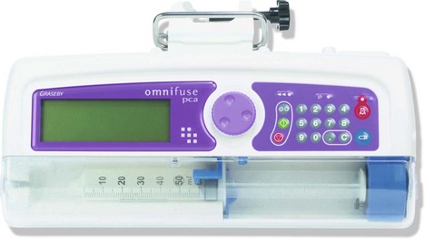
Patient controlled analgesia (PCA)
Mechanism of action
1. Different modes of analgesic administration can be employed:
a) patient controlled on-demand bolus administration (PCA)
b) continuous background infusion and patient controlled bolus administration.
2. The initial programming of the pump must be tailored for the individual patient. The mode of administration, the amount of analgesic administered per bolus, the ‘lock-out’ time (i.e. the time period during which the patient is prevented from receiving another bolus despite activating the demand button), the duration of the administration of the bolus and the maximum amount of analgesic permitted per unit time are all variable settings on a PCA device.
3. Some designs have the capability to be used as a PCA pump for a particular variable duration then switching automatically to a continuous infusion as programmed.
4. The history of the drug administration including the total dose of the analgesic, the number of boluses and the number of successful and failed attempts can be displayed.
5. The devices have memory capabilities so they retain their programming during syringe changing.
6. Tamper-resistant features are included.
7. Some designs have a safety measure where an accidental triggering of the device is usually prevented by the need for the patient to make two successive presses on the hand control within 1 second.
8. PCA devices operate on mains or battery.
9. Different routes of administration can be used for PCA, e.g. intravenous, intramuscular, subcutaneous or epidural routes.
10. Alarms are included for malfunction, occlusion and disconnection.
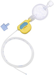
11. Ambulatory PCA pumps are available allowing patient’s mobilization during use (Fig. 12.2).
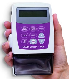
Fig. 12.2 The CADD Legacy portable PCA.
Problems in practice and safety features
1. The ability of the patient to co-operate and understand is essential.
2. Availability of trained staff to programme the device and monitor the patient is vital.
3. In the PCA mode, the patient may awaken in severe pain because no boluses were administered during sleep.
4. Some PCA devices require special giving sets and syringes.
Syringe pumps
These are programmable pumps that can be adjusted to give variable rates of infusion and also bolus administration (Fig. 12.3). They are used to maintain continuous infusions of analgesics (or other drugs). The type of flow is pulsatile continuous delivery and their accuracy is within ±2–5%. Some designs can accept a variety of different size syringes. The power source can be battery and/or mains.
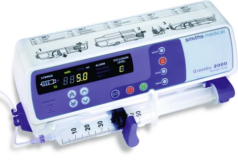
Fig. 12.3 The Graseby 2000 syringe pump.
Volumetric pumps
These are programmable pumps designed to be used with specific giving set tubing (Fig. 12.4). They are more suitable for infusions where accuracy of total volume is more important than precise flow rate. Their accuracy is generally within ±5–10%. Volumetric pump accuracy is sensitive to the internal diameter of the giving set tubing. Various mechanisms of action exist. Peristaltic, cassette and reservoir systems are commonly used.
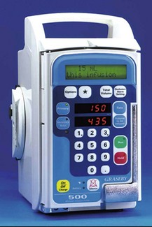
Fig. 12.4 The Graseby volumetric pump.
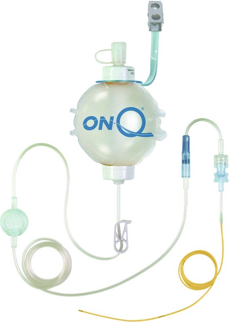
Elastomeric pumps
These recently designed light, portable and disposable pumps allow continous infusions of local anaesthetic solutions. Continuous incisional infiltration or nerve blocks can be used so allowing the delivery of continuous analgesia (Fig. 12.5).
Mechanism of action
1. The balloon deflates slowly and spontaneously delivering a set amount of local anaesthetic solution per hour. Rates of 2–14 mL/h can be programmed.
2. Catheters are designed with multiple orifices allowing the infusion of local anaesthetic solution over a large area.
3. An extra on-demand bolus facility is available in some designs. This allows boluses of 5 mL solution with a lock-out time of 60 min.
4. Some designs allow the simultaneous infusion of two surgical sites.
5. Silver-coated dressing for anti-microbial effect is provided.
Problems in practice and safety features
1. Some of the local anaesthetic may get absorbed into the balloon.
2. The infusion rate profile can vary throughout the infusion. It is thought that the initial rate is higher than expected initially especially if the pump is under filled. The infusion rates tend to decrease over the infusion period.
3. It is important to follow the manufacturer’s instructions regarding positioning of the device in relation to the body and ambient temperature. Changes in temperature can affect the flow rate. A change of 10°C in the temperature of water-based fluids results in altered viscosity, which causes a 20–30% change in flow rate.
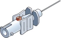
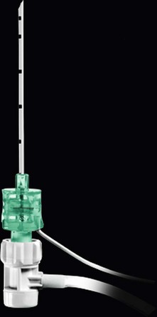
Epidural needles
Epidural needles are used to identify and cannulate the epidural space. The Tuohy needle is widely used in the UK (Fig. 12.6).
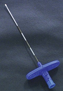
Components
1. The needle is 10 cm in length with a shaft of 8 cm (with 1-cm markings). A 15-cm version exists for obese patients.
2. The needle wall is thin in order to allow a catheter to be inserted through it.
3. The needle is provided with a stylet introducer to prevent occlusion of the lumen by a core of tissue as the needle is inserted.
4. The bevel (called a Huber point) is designed to be slightly oblique at 20° to the shaft, with a rather blunt leading edge.
5. Some designs allow the wings at the hub to be added or removed.
Mechanism of action
1. The markings on the needle enable the anaesthetist to determine the distance between the skin and the epidural space. Hence the length of the catheter left inside the epidural space can be estimated.
2. The shape and design of the bevel (Fig 12.7) enable the anaesthetist to direct the catheter within the epidural space (either in a cephalic or caudal direction).
3. The bluntness of the bevel also minimizes the risk of accidental dural puncture.
4. Some anaesthetists prefer winged epidural needles for better control and handling of the needle during insertion.
5. A paediatric 19-G, 5-cm long Tuohy needle (with 0.5-cm markings), allowing the passage of a 21-G nylon catheter, is available.
6. A combined spinal–epidural technique is possible using a 26-G spinal needle of about 12 cm length with a standard 16-G Tuohy needle. The Tuohy needle is first positioned in the epidural space then the spinal needle is introduced through it into the subarachnoid space (Fig. 12.7). A relatively high pressure is required to inject through the spinal needle because of its small bore. This might lead to accidental displacement of the tip of the needle from the subarachnoid space leading to a failed or partial block. To prevent this happening, in some designs, the spinal needle is ‘anchored’ to the epidural needle to prevent displacement (Fig. 12.8).
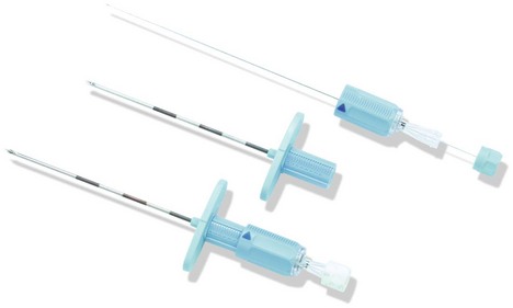
Problems in practice and safety features
1. During insertion of the catheter through the needle, if it is necessary to withdraw the catheter, the needle must be withdrawn simultaneously. This is because of the risk of the catheter being transected by the oblique bevel.
2. In accidental dural puncture, there is a high incidence of postdural headache due to the epidural needle’s large bore (e.g. 16 G or 18 G).
3. Wrong route errors: in order to avoid administering drugs that were intended for intravenous administration, all epidural bolus doses are performed using syringes, needles and other devices with safer connectors that cannot connect with intravenous Luer connectors.
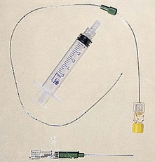
Epidural catheter, filter and loss of resistance device (Fig. 12.9)
Components

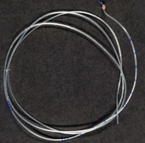
1. 90-cm transparent, malleable tube made of either nylon or Teflon and biologically inert. The 16-G version has an external diameter of about 1 mm and an internal diameter of 0.55 mm.
2. The distal end has two or three side ports with a closed and rounded tip in order to reduce the risk of vascular or dural puncture (see Fig. 12.7). Paediatric designs, 18 G or 19 G, have closer distal side ports.
3. Some designs have an open end.
4. The distal end of the catheter is marked clearly at 5-cm intervals, with additional 1-cm markings between 5 and 15 cm (Fig. 12.10).
5. The proximal end of the catheter is connected to a Luer lock and a filter (Fig. 12.10).
6. In order to prevent kinking, some designs incorporate a coil-reinforced catheter.
7. Some designs are radio-opaque. These catheters tend to be more rigid than the normal design. They can be used in patients with chronic pain to ensure correct placement of the catheter.
Mechanism of action
1. The catheters are designed to pass easily through their matched gauge epidural needles.
2. The markings enable the anaesthetist to place the desired length of catheter within the epidural space (usually 3–5 cm).
3. There are catheters with a single port at the distal tip. These offer a rather sharp point and increase the incidence of catheter-induced vascular or dural puncture.
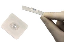
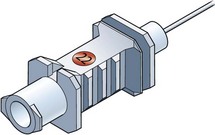
4. An epidural fixing device can be used to prevent the catheter falling out. The device clips on the catheter. It has an adhesive flange that secures it to the skin. The device does not occlude the catheter and does not increase the resistance to injection (Fig. 12.11).
Problems in practice and safety features
1. The patency of the catheter should be tested prior to insertion.
2. The catheter can puncture an epidural vessel or the dura at the time of insertion or even days later.
3. The catheter should not be withdrawn through the Tuohy needle once it has been threaded beyond the bevel as that can transect the catheter. Both needle and catheter should be removed in unison.
4. It is almost impossible to predict in which direction the epidural catheter is heading when it is advanced.
5. Once the catheter has been removed from the patient, it should be inspected for any signs of breakage. The side ports are points of catheter weakness where it is possible for the catheter to break. Usually, if a portion of the catheter were to remain in the patient after removal, conservative management would be recommended.
6. Advancing the catheter too much can cause knotting (Fig. 12.12).
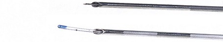
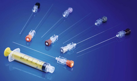
Spinal needles
These needles are used to inject local anaesthetic(s) and/or opiates into the subarachnoid space. In addition, they are used to sample cerebrospinal fluid (CSF) or for intrathecal injections of antibiotics and cytotoxics (Fig. 12.13).
Components
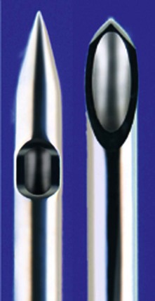
1. The needle’s length varies from 5 to 15 cm; the 10-cm version is most commonly used. They have a transparent hub in order to identify quickly the flow of CSF.
2. A stylet is used to prevent a core of tissue occluding the lumen of the needle during insertion. It also acts to strengthen the shaft. The stylet is withdrawn once the tip of the needle is (or is suspected to be) in the subarachnoid space.
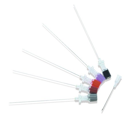
3. Spinal needles are made in different sizes, from 18 G to 29 G in diameter. 32-G spinal needles have been described but are not widely used.
4. The 25-G and smaller needles are used with an introducer which is usually an 18-G or 19-G needle.
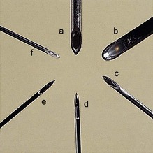
5. There are two designs for the bevel. The cutting, traumatic bevel is seen in the Yale and Quincke needles. The non-cutting, atraumatic pencil point, with a side hole just proximal to the tip, is seen in the Whitacre and Sprotte needles (Figs 12.14 and 12.15).
6. A 28-G nylon, open-ended microcatheter can be inserted through a Crawford spinal needle (23 G). A stylet inside the catheter is removed during the insertion. This allows top-ups to be administered. The priming volume is 0.03 mL with a length of 910 mm. A 0.2-micron filter is attached to the catheter (Fig. 12.16).
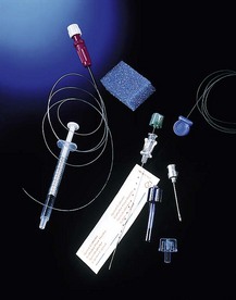
Fig. 12.16 The Portex spinal microcatheter set.
Mechanism of action
1. The large 22-G needle is more rigid and easier to direct. It gives a better feedback feel as it passes through the different tissue layers.
2. The CSF is slower to emerge from the smaller sized needles. Aspirating gently with a syringe can speed up the tracking back of CSF.
3. Continuous spinal anaesthesia can be achieved by inserting 3–4 cm of the 28-G spinal microcatheter into the subarachnoid space.
Problems in practice and safety features
1. Wrong route errors: in order to avoid administering drugs that were intended for intravenous administration, all spinal (intrathecal) bolus doses and lumbar puncture samples are performed using syringes, needles and other devices with safer connectors that cannot connect with intravenous Luer connectors (Figs 12.17 and 12.18).
Dural headache
1. The incidence of dural headache is directly proportional to the gauge of the needle and the number of punctures made through the dura and indirectly proportional to the age of the patient. There is a 30% incidence of dural headache using a 20-G spinal needle, whereas the incidence is reduced to about 1% when a 26-G needle is used. For this reason, smaller gauge spinal needles are preferred.
2. The Whitacre and Sprotte atraumatic needles separate rather than cut the longitudinal fibres of the dura. The defect in the dura has a higher chance of sealing after the removal of the needles. This reduces the incidence of dural headache.
3. Traumatic bevel needles cut the dural fibres, producing a ragged tear which allows leakage of CSF. Dural headache is thought to be caused by the leakage of CSF.
4. The risk of dural headache is higher during pregnancy and labour, day-surgery patients and those who have experienced a dural headache in the past.
Nerve block needles
These needles are used in regional anaesthesia to identify a nerve plexus or peripheral nerve (Fig. 12.19).
Components
1. They are made of steel with a Luer-lock attachment.
2. They have short, rather blunt bevels in order to cause minimal trauma to the nervous tissue. The bluntness makes skin insertion more difficult. This can be overcome by a small incision.
3. The needles have transparent hubs which allow earlier recognition of intravascular placement while performing blocks.
4. A side port for injecting the local anaesthetic solution is found in some designs.
5. The needles are connected to a nerve stimulator to aid in localizing the nerve using an insulated cable to prevent leakage of current (see Chapter 14).
6. 22-G size needles are optimal for the vast majority of blocks. There are different lengths depending on the depth of the nerve or plexus. Some suggested length needles for common blocks are:
a) interscalene block: 25–50 mm
c) psoas compartment block: 80–120 mm
e) sciatic nerve block (depending on the approach): 80–150 mm.
7. A pencil-shaped needle tip with a distal side hole for injecting local anaesthetic drugs is available.
Mechanism of action
1. The needle should first be introduced through the skin and subcutaneous tissues and then attached to the lead of the nerve stimulator.
2. An initial high output (e.g. 1–3 mA) from the nerve stimulator is selected. For superficial nerves, a starting current of 1–2 mA should be sufficient in most cases. For deeper nerves, it may be necessary to increase the initial current to 3 mA or even more. The needle is advanced slowly towards the nerve until nerve stimulation is noticed. The output is then reduced until a maximal stimulation is obtained with the minimal output. This current should be 0.2–0.4 mA. Contractions with such a low current mean that the tip of the needle is touching or very close to the nerve. Higher currents suggest that the needle is unlikely to be near the nerve. Contractions at a current less than 0.2 mA may indicate possible intraneural needle placement.
3. The blunt nerve block needle pushes the nerve ahead of itself as it is advanced, whereas a sharp needle is more likely to pierce the nerve. Blunt needles give a better feedback feel as resistance changes as they pass through the different layers of tissues.
4. As the local anaesthetic solution is injected, the stimulation is markedly reduced after only a small volume (about 2 mL) is injected. This is due to displacement of the nerve by the needle tip. Failure of the twitching to disappear (or pain experienced by the awake patient) after injection may indicate intraneural needle placement.
5. The immobile needle technique is used for major nerve and plexus blocks when a large volume of local anaesthetic solution is used. One operator maintains the needle in position, while the second operator, after aspiration, injects the local anaesthetic solution through the side port. This technique reduces the possibility of accidental misplacement and intravascular injection.
6. Catheters can be inserted and left in situ after localizing the nerve or plexus (Fig. 12.20). Repeat bolus or continuous infusion of local anaesthetic solution can then be administered. Catheter techniques can be used to enhance the spread (such as in the axillary block) or to prolong the duration of the block.
7. Stimulating catheters can also be inserted to provide a continuous block. The catheter body is made from insulating plastic material and usually contains a metallic wire, inside which conducts the current to its exposed tip electrode. Usually, such stimulating catheters are placed using a continuous nerve block needle which is placed first using nerve stimulation. It acts as an introducer needle for the catheter. Once this needle is placed close to the nerve or plexus to be blocked, the stimulating catheter is introduced through it and the nerve stimulator is connected to the catheter. Stimulation through the catheter should reconfirm the catheter tip position in close proximity to the target nerve(s). However, it must be noted that the threshold currents with stimulating catheters may be considerably higher. Injection of local anaesthetic or saline (which is frequently used to widen the space for threading the catheter more easily) should be avoided, as this may increase the threshold current considerably and may even prevent a motor response.
Nerve block needles can either be insulated with an exposed tip or non-insulated.
Insulated needles
These needles are Teflon coated with exposed tips. The current passes through the tip only (Fig. 12.21). The insulated needles have a slightly greater diameter than similar non-insulated needles, which may result in a higher risk of nerve injury. The plexus or nerve can be identified with a smaller current than that required using the non-insulated needles.
Non-insulated needles
These needles allow current to pass through the tip as well the shaft (Fig. 12.21). They are effective in regional anaesthesia because the maximum density of the current is being localized to the tip because of its lower resistance. However, a nerve may be stimulated via the shaft. In this situation, the local anaesthetic solution injected will be placed away from the nerve resulting in an unsuccessful block.
Percutaneous localization of nerves
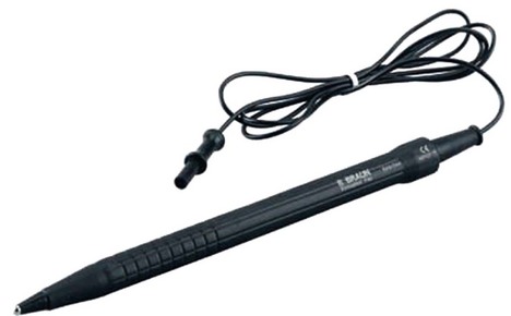
This recent new technique allows rapid, relatively painless and non-invasive localization of superficial nerves using a pen-like device (Fig. 12.22). This technique allows the identification of the optimal angle and needle entry point before introducing the needle into the patient. Such a device can be used to identify nerves up to 3 cm in depth.
Nerve stimulator for nerve blocks
This device is designed to produce visible muscular contractions at a predetermined current and voltage once a nerve plexus or peripheral nerve(s) has been located, without actually touching it, thereby providing a greater accuracy for local anaesthetic deposition (Fig. 12.23).
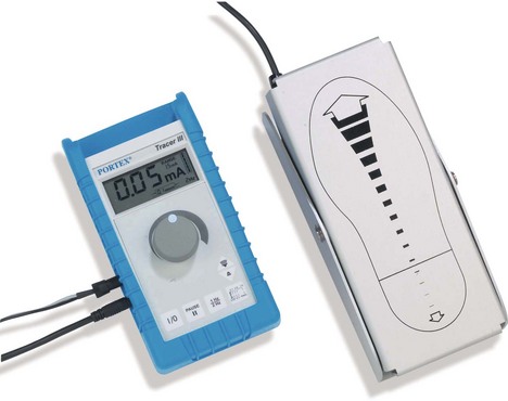
Fig. 12.23 The Portex Tracer III peripheral nerve stimulatort. Note its facility for remote control.
Components
1. The nerve stimulator case with an on/off switch and a dial selecting the amplitude of the current.
2. Two leads to complete the circuit. One is connected to an ECG skin electrode and the other to the locating needle. The polarity of the leads should be clearly indicated and colour-coded with the negative lead being attached to the needle.
Mechanism of action
1. A small constant current (0.25–0.5 mA) is used to stimulate the nerve fibres causing the motor fibres to contract. Less current is needed if the needle is connected to the negative lead than to the positive lead. When the negative (cathode) lead is used to locate the nerve, the current causes changes in the resting membrane potential of the cells, producing an area of depolarization and so causing an action potential. If the stimulating electrode is positive (anode), the current causes an area of hyperpolarization near the needle tip and a ring of depolarization distal to the tip. This requires a much higher current.
2. The frequency is set at 1–2 Hz. Tetanic stimuli are not used because of the discomfort caused. Using 2-Hz frequency allows more frequent feedback.
3. The duration of the stimulus should be short (50–100 ms) to generate painless motor contraction.
4. The nerve stimulator is battery operated to improve patient safety.
5. Nerve location can be very accurately defined, especially when low currents are used. The success rate of technically difficult nerve blocks can be increased by using a nerve stimulator. A sciatic nerve block with a success rate of over 90% can be achieved in experienced hands, compared to about 50% without using a nerve stimulator.
6. Remote control of the nerve stimulator allows sterile one-hand operation (Figs 12.23 and 12.24).
Problems in practice and safety features
1. Higher currents will stimulate nerve fibres even if the tip of the needle is not adjacent to the nerve. The muscle fibres themselves can also be directly stimulated when a high current is used. In both situations, the outcome will be an unsuccessful block once the local anaesthetic solution has been injected.
2. The positive ground electrode should have good contact with clear dry skin. As the current flows between the two electrodes (needle and ground), it is preferable not to position the ground over a superficial nerve. The passage of the current through the myocardium should also be avoided.
3. Most stimulators have a connection/disconnection indicator to ensure that the operator is aware of the delivery or not of stimulus current.
4. It is not recommended to use nerve stimulators designed to monitor the extent of neuromuscular blockade for regional nerve blocks. These are high-output devices which can damage the nervous tissue.
5. It should be remembered that using the nerve stimulator is no excuse for not having the sound knowledge of surface and neuroanatomy required to perform regional anaesthesia.
Ultrasound guidance in regional anaesthesia
More specially designed needles for the use of ultrasound are available allowing a better reflection of the ultrasound waves (Fig. 12.25). The needles have echogenic laser markings to facilitate better needle visualization with minimal acoustic shadowing.
Dalrymple P., Chelliah S. Electrical nerve locators. Continuing Education in Anaesthesia. Critical Care and Pain. 2006;6(1):32–36.
Keay S., Callander C. The safe use of infusion devices. Continuing Education in Anaesthesia. Critical Care and Pain. 2004;4(3):81–85.
Marhofer P., Greher M., Kapral S. Ultrasound guidance in regional anaesthesia. British Journal of Anaesthesia. 2005;94(1):7–17.
MHRA. Intravascular and epidural devices – top tips. Online. Available at: http://www.mhra.gov.uk/Publications/Postersandleaflets/CON2025731, 2007.
MHRA. Infusion systems, DB 2003(02) v2.0. Online. Available at: http://www.mhra.gov.uk/Publications/Safetyguidance/DeviceBulletins/CON007321, 2010.
NHS. Epidural injections and infusions. Online. Available at: http://www.nrls.npsa.nhs.uk/resources/?entryid45=59807&p=11, 2007.
NHS. Safer ambulatory syringe drivers. Online. Available at: http://www.nrls.npsa.nhs.uk/resources/?entryid45=92908&p=2, 2010.
NHS. Design for patient safety: a guide to the design of electronic infusion devices. Online. Available at: http://www.nrls.npsa.nhs.uk/resources/?entryid45=68534&p=4, 2010.
NHS. Safer spinal (intrathecal), epidural and regional devices. Online. Available at: http://www.nrls.npsa.nhs.uk/resources/?entryid45=94529&p=2, 2011.
Obstetric Anaesthetists’ Association. Spinal/epidural needle design. Online. Available at: http://oaa-anaes.ac.uk/content.asp?contentid=367, 2012.
The Royal College of Anaesthetists. Good practice in the management of continuous epidural analgesia in the hospital setting. Online. Available at: www.rcoa.ac.uk/docs/Epid.Analg.pdf, 2004.
In the following lists, which of the statements (a) to (e) are true?
1. Epidural catheters and filters:
a) A minimum of 10 cm of the catheter should be inserted into the epidural space.
b) The catheter should not be withdrawn through the Tuohy needle once it has been threaded beyond the bevel.
c) Catheters with a single port at the distal tip reduce the incidence of vascular or dural puncture.
2. Regional anaesthesia using a nerve stimulator:
a) The needles used have sharp tips to aid in localizing the nerves/plexuses.
b) AC current is used to locate the nerve.
c) A current of 1 A is usually used to locate a nerve.
3. Nerve stimulators in regional anaesthesia:
a) They enable the block to be performed even without full knowledge of the anatomy.
b) In the insulated nerve block needle, the current passes through the tip only.
c) In the non-insulated nerve block needle, the current passes through the tip and the shaft.
d) A catheter can be used for continuous nerve/plexus blockade.
e) The immobile needle technique improves the success rate of the block.
4. Incidence of spinal headache:
a) Yale and Quincke needle design have lower incidence of spinal headache.
b) It is inversely proportional to the size of the needle used.
c) It is similar in young and elderly patients.
5. Which of the following is/are true:
a) Using ultrasound guidance in regional anaesthesia, a frequency range of 10–14 kHz is adequate.
b) It is important to prevent free flow from the syringe pump.
c) There is no need to use anti-reflux valves in other infusion lines.
d) Sector transducers can achieve better images when in regional anaesthesia.
e) Syringe pumps should be positioned at the same level as the patient.
1. Epidural catheters and filters:
a) False. 3–5 cm of the catheter is left in the epidural space. This reduces the incidence of vascular or dural puncture, segmental or unilateral block (as the catheter can pass through an intervertebral foramina) and knotting.
b) True. The withdrawal of the catheter through the Tuohy needle after it has been threaded beyond the bevel can lead to the transection of the catheter. This usually happens when the catheter punctures a vessel during insertion. The needle and the catheter should be removed together and another attempt should be made to reinsert the needle and catheter.
c) False. Catheters with a single port at the distal tip increase the incidence of vascular or dural puncture. This is due to the ‘sharp’ point at the end of the catheter. In contrast, catheters with side ports have a closed and rounded end thus reducing the incidence of vascular or dural puncture.
d) False. The filter can be used for up to 24 h.
e) True. Some catheters are designed to be radio-opaque. They are more rigid than the standard design. They are mainly used in patients with chronic pain to ensure the correct placement of the catheter.
2. Regional anaesthesia using a nerve stimulator:
a) False. There is a need for feedback from the needle as it goes through the different layers of tissue. A sharp needle will pass the different layers of tissues easily with minimal feedback. A blunt needle will provide much better feedback.
b) False. DC current from a battery is used to operate nerve stimulators. By avoiding AC current, patient safety is improved.
c) False. This is a very high current. A current range of up to 5 mA is needed in locating the nerve. A current of 0.25–0.5 mA is used to stimulate the nerve fibres. Using a very high current, the tip of the needle might be far away from the nerve but might still lead to stimulation of the nerve fibres or the muscle fibres directly leading to the failure of the block.
d) True. There is no need for paraesthesia in order to achieve a successful block using a nerve stimulator. Paraesthesia implies that the needle is touching the nerve. With a nerve stimulator, the nerve can be stimulated electrically without being touched.
e) False. Stimuli with a frequency of 1–2 Hz are used. Tetanic stimuli (e.g. 50-Hz frequency) are not used because of the discomfort caused.
3. Nerve stimulators in regional anaesthesia:
a) False. Full knowledge of the anatomical structure is essential for a successful block.
b) True. As the tip is the only non-insulated part of the needle, the current passes only through it. Using a small current, the tip of the needle has to be very close to the nerve before stimulation is visible.
c) True. In a non-insulated needle, the current passes through both the tip and shaft. This might lead to nerve stimulation by current from the shaft even when the tip is far away from the nerve. This obviously leads to a failed block.
d) True. After successful nerve stimulation, a catheter can be inserted. This allows a prolonged and continuous block using an infusion or boluses.
e) True. The immobile needle technique allows one operator to maintain the needle in the correct position while the second operator injects the local anaesthetic. This also reduces the risk of accidental intravascular injection.
4. Incidence of spinal headache:
a) False. Yale and Quincke have a higher incidence of spinal headache. This is due to the traumatic bevel cutting the dural fibres producing a ragged tear which allows CSF leakage.
b) False. The incidence is directly proportional to the size of the needle used. Using a 20-G spinal needle causes a 30% incidence of spinal headache whereas a 26-G needle has a 1% incidence of headache.
c) False. The incidence of spinal headache is much higher in the young than in elderly patients.
d) True. The incidence of spinal headache is increased with multiple dural punctures.
e) True. The pencil-shaped needle tip separates rather than cuts the longitudinal dural fibres. After removal of the needle, the dura has a higher chance of sealing, reducing the incidence of spinal headache.
5. Which of the following is/are true:
a) False. The frequencies needed for nerve blocks are in the range of 10–14 MHz. Most modern ultrasound devices can generate these frequencies.
b) True. Anti-siphon valves are used to prevent free flow from the syringe pump. In addition, the syringe should be securely clamped to the pump. Siphoning can also occur if there is a crack in the syringe allowing air entry.
c) False. An anti-reflux valve should be inserted in any other line that is connected to the infusion line. Anti-reflux valves prevent backflow up the secondary (usually with lower pressure) should a distal occlusion occur and avoid a subsequent inadvertent bolus.
d) False. Sector transducers emit diverging sound waves, such that the echotexture of the nerves will only be displayed in the centre of the image. The true echogenicity of a nerve is only captured if the sound beam is oriented perpendicularly to the nerve axis. This can best be achieved with linear array transducers with parallel sound beam emission.
e) True. Gravitational pressure can be generated to overcome the friction between a non-secured plunger and barrel especially if the pump is positioned more than 100 cm above the patient.
[/level-membership-for-anesthesiology-category][not-level-membership-for-anesthesiology-category]
Pain management and regional anaesthesia
Patient controlled analgesia (PCA)
Mechanism of action
1. Different modes of analgesic administration can be employed:
a) patient controlled on-demand bolus administration (PCA)
b) continuous background infusion and patient controlled bolus administration.
2. The initial programming of the pump must be tailored for the individual patient. The mode of administration, the amount of analgesic administered per bolus, the ‘lock-out’ time (i.e. the time period during which the patient is prevented from receiving another bolus despite activating the demand button), the duration of the administration of the bolus and the maximum amount of analgesic permitted per unit time are all variable settings on a PCA device.
3. Some designs have the capability to be used as a PCA pump for a particular variable duration then switching automatically to a continuous infusion as programmed.
4. The history of the drug administration including the total dose of the analgesic, the number of boluses and the number of successful and failed attempts can be displayed.
5. The devices have memory capabilities so they retain their programming during syringe changing.
6. Tamper-resistant features are included.
7. Some designs have a safety measure where an accidental triggering of the device is usually prevented by the need for the patient to make two successive presses on the hand control within 1 second.
8. PCA devices operate on mains or battery.
9. Different routes of administration can be used for PCA, e.g. intravenous, intramuscular, subcutaneous or epidural routes.
10. Alarms are included for malfunction, occlusion and disconnection.
11. Ambulatory PCA pumps are available allowing patient’s mobilization during use (Fig. 12.2).
Fig. 12.2 The CADD Legacy portable PCA.
Problems in practice and safety features
1. The ability of the patient to co-operate and understand is essential.
2. Availability of trained staff to programme the device and monitor the patient is vital.
3. In the PCA mode, the patient may awaken in severe pain because no boluses were administered during sleep.
4. Some PCA devices require special giving sets and syringes.
Syringe pumps
These are programmable pumps that can be adjusted to give variable rates of infusion and also bolus administration (Fig. 12.3). They are used to maintain continuous infusions of analgesics (or other drugs). The type of flow is pulsatile continuous delivery and their accuracy is within ±2–5%. Some designs can accept a variety of different size syringes. The power source can be battery and/or mains.
Fig. 12.3 The Graseby 2000 syringe pump.
Volumetric pumps
These are programmable pumps designed to be used with specific giving set tubing (Fig. 12.4). They are more suitable for infusions where accuracy of total volume is more important than precise flow rate. Their accuracy is generally within ±5–10%. Volumetric pump accuracy is sensitive to the internal diameter of the giving set tubing. Various mechanisms of action exist. Peristaltic, cassette and reservoir systems are commonly used.
Fig. 12.4 The Graseby volumetric pump.
Elastomeric pumps
These recently designed light, portable and disposable pumps allow continous infusions of local anaesthetic solutions. Continuous incisional infiltration or nerve blocks can be used so allowing the delivery of continuous analgesia (Fig. 12.5).
Mechanism of action
1. The balloon deflates slowly and spontaneously delivering a set amount of local anaesthetic solution per hour. Rates of 2–14 mL/h can be programmed.
2. Catheters are designed with multiple orifices allowing the infusion of local anaesthetic solution over a large area.
3. An extra on-demand bolus facility is available in some designs. This allows boluses of 5 mL solution with a lock-out time of 60 min.
4. Some designs allow the simultaneous infusion of two surgical sites.
5. Silver-coated dressing for anti-microbial effect is provided.
Problems in practice and safety features
1. Some of the local anaesthetic may get absorbed into the balloon.
2. The infusion rate profile can vary throughout the infusion. It is thought that the initial rate is higher than expected initially especially if the pump is under filled. The infusion rates tend to decrease over the infusion period.
3. It is important to follow the manufacturer’s instructions regarding positioning of the device in relation to the body and ambient temperature. Changes in temperature can affect the flow rate. A change of 10°C in the temperature of water-based fluids results in altered viscosity, which causes a 20–30% change in flow rate.
Epidural needles
Epidural needles are used to identify and cannulate the epidural space. The Tuohy needle is widely used in the UK (Fig. 12.6).
Components
1. The needle is 10 cm in length with a shaft of 8 cm (with 1-cm markings). A 15-cm version exists for obese patients.
2. The needle wall is thin in order to allow a catheter to be inserted through it.
3. The needle is provided with a stylet introducer to prevent occlusion of the lumen by a core of tissue as the needle is inserted.
4. The bevel (called a Huber point) is designed to be slightly oblique at 20° to the shaft, with a rather blunt leading edge.
5. Some designs allow the wings at the hub to be added or removed.
Mechanism of action
1. The markings on the needle enable the anaesthetist to determine the distance between the skin and the epidural space. Hence the length of the catheter left inside the epidural space can be estimated.
2. The shape and design of the bevel (Fig 12.7) enable the anaesthetist to direct the catheter within the epidural space (either in a cephalic or caudal direction).
3. The bluntness of the bevel also minimizes the risk of accidental dural puncture.
4. Some anaesthetists prefer winged epidural needles for better control and handling of the needle during insertion.
5. A paediatric 19-G, 5-cm long Tuohy needle (with 0.5-cm markings), allowing the passage of a 21-G nylon catheter, is available.
6. A combined spinal–epidural technique is possible using a 26-G spinal needle of about 12 cm length with a standard 16-G Tuohy needle. The Tuohy needle is first positioned in the epidural space then the spinal needle is introduced through it into the subarachnoid space (Fig. 12.7). A relatively high pressure is required to inject through the spinal needle because of its small bore. This might lead to accidental displacement of the tip of the needle from the subarachnoid space leading to a failed or partial block. To prevent this happening, in some designs, the spinal needle is ‘anchored’ to the epidural needle to prevent displacement (Fig. 12.8).
Problems in practice and safety features
1. During insertion of the catheter through the needle, if it is necessary to withdraw the catheter, the needle must be withdrawn simultaneously. This is because of the risk of the catheter being transected by the oblique bevel.
2. In accidental dural puncture, there is a high incidence of postdural headache due to the epidural needle’s large bore (e.g. 16 G or 18 G).
3. Wrong route errors: in order to avoid administering drugs that were intended for intravenous administration, all epidural bolus doses are performed using syringes, needles and other devices with safer connectors that cannot connect with intravenous Luer connectors.
Epidural catheter, filter and loss of resistance device (Fig. 12.9)
Components
1. 90-cm transparent, malleable tube made of either nylon or Teflon and biologically inert. The 16-G version has an external diameter of about 1 mm and an internal diameter of 0.55 mm.
2. The distal end has two or three side ports with a closed and rounded tip in order to reduce the risk of vascular or dural puncture (see Fig. 12.7). Paediatric designs, 18 G or 19 G, have closer distal side ports.
3. Some designs have an open end.
4. The distal end of the catheter is marked clearly at 5-cm intervals, with additional 1-cm markings between 5 and 15 cm (Fig. 12.10).
5. The proximal end of the catheter is connected to a Luer lock and a filter (Fig. 12.10).
6. In order to prevent kinking, some designs incorporate a coil-reinforced catheter.
7. Some designs are radio-opaque. These catheters tend to be more rigid than the normal design. They can be used in patients with chronic pain to ensure correct placement of the catheter.
Mechanism of action
1. The catheters are designed to pass easily through their matched gauge epidural needles.
2. The markings enable the anaesthetist to place the desired length of catheter within the epidural space (usually 3–5 cm).
3. There are catheters with a single port at the distal tip. These offer a rather sharp point and increase the incidence of catheter-induced vascular or dural puncture.
4. An epidural fixing device can be used to prevent the catheter falling out. The device clips on the catheter. It has an adhesive flange that secures it to the skin. The device does not occlude the catheter and does not increase the resistance to injection (Fig. 12.11).
