[level-membership-for-anesthesiology-category]
Chapter 20 Medical suction apparatus
Main components
The main components of a medical suction system are:
The schematic drawings in Fig. 20.1 outline the methods used in suction apparatus, using internationally agreed symbols.
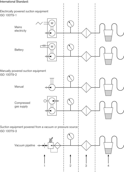
Energy source
Suction apparatus requires an energy source that generates a sub-atmospheric pressure. This is colloquially referred to as a vacuum source, despite the fact that a true (high) vacuum is rarely achieved. In fact, the pressure required is only a maximum of 60 kPa less than the normal environmental pressure (see Further reading).
Vacuum source
The sub-atmospheric pressure required may be generated by:
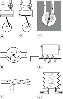
• an electric motor or other source of rotational energy that may be used to drive a mechanical pump, various forms of which are shown in Figs 20.2A–E.
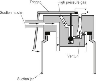
• pneumatically driven pumps that usually work on the Venturi principle (Fig. 20.2F). The driving force may be air, oxygen, steam or water
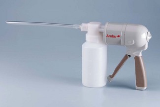
• a manually (or foot) operated spring-loaded bellows arrangement with unidirectional valves (Fig. 20.2G).
Pump types
Fig. 20.2A shows a piston pump, which is capable of creating high vacuum but, in transportable models, has a relatively low displacement (i.e. can only sustain low flow rates). Fig. 20.2B shows a diaphragm pump, which is a variation of the piston pump. It is mechanically simpler but is also frequently much noisier. One reason for the increased noise is that often, rather than using a conventional rotating electric motor, a much simpler large electromagnet displaces the diaphragm. Fig. 20.2C shows a form of rotary pump that can produce a high vacuum without conventional one-way valves. Fig. 20.2D shows a rotary pump capable of producing very high flows, as would be required in a dental surgery. It works in the same way as a vacuum cleaner and has the disadvantage of being extremely noisy. Fig. 20.2E shows a pump that works on the principle of the Archimedean screw. This type of pump can produce a high vacuum for a comparatively small size of machine. Fig. 20.2F shows the principle of a Venturi pump which makes use of the Bernoulli effect. Compressed fluid (gas or liquid), passing through a narrow orifice, creates a region of negative pressure beyond that orifice, which can be used to entrain adjacent air/debris. The main disadvantage of this simple affair is that it uses and is thus wasteful of large volumes of driving fluid, which is usually oxygen from cylinders. However, it does have the virtue of being extremely portable (Fig. 20.3). Finally, Fig. 20.2G shows a simple bellows mechanism with a pair of one-way valves, as would be used in manually operated suction apparatus.
Collection vessel
The collection vessel stores the aspirate prior to its disposal. It needs to be of sufficient volume to hold enough aspirate so that it does not need emptying too often. However, the larger its volume, the greater the displacement that is necessary from the pump, in order to reduce the pressure in the vessel before aspiration can occur efficiently. It is important that the inlet to the collection vessel has an internal diameter sufficiently large to admit the largest particles expected in the particular application of the apparatus (see Further Reading).
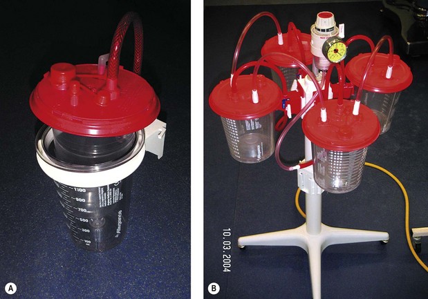
To minimize risks of contamination to theatre staff, all suction apparatus, except portable emergency units, should make use of a disposable collection system (Fig. 20.4A). This usually consists of a rigid outer transparent container with volume markings on its side and an inner (transparent) disposable plastic sleeve with an integral lid. The aspirate is stored in the inner sleeve and when full is capped off and discarded. As it is disposed of with other clinical waste, a gelling agent should be added to the vessel so as to solidify the contents to prevent accidental spillage. Thus, staff should never come into contact with any aspirate.
Efficiency
The efficiency of suction apparatus depends upon:
• the degree of vacuum (sub-atmospheric pressure) that can be produced by the pump, with particular regard to the time taken to achieve it
• the displacement, i.e. the volume of air at atmospheric pressure that the pump is able to move in unit time
• the internal resistance of the suction apparatus as a whole. This is related not only to the length and diameter of tubing and other components, but also to the tubing and other accessories between the apparatus and the liquid being aspirated
Other components of suction apparatus
Cut-off over-flow valve
In order to test both the collection vessel and especially its inlet and also the cut-off overflow valve, an international standard test vomit has been specified. It consists of food-grade xantham gum, water and 1 mm glass beads (see Further reading).
Multiple collection vessels
Modern suction apparatus usually has two collection vessels with a manually operated valve, so that the vacuum source can be rapidly switched from a full vessel to a fresh one. Alternatively, where large volumes of aspirate are anticipated, a number of collection vessels are connected in series in a carousel with all the individual valves open. Here, aspirate overflows from the first vessel into the next and so on (Fig. 20.4B). When the accurate estimation of small volumes of aspirate is required, as in paediatric surgery, a small calibrated vessel may be used in addition to the main apparatus. This container is disposable and is usually close to the operative field.
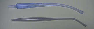
The suction nozzle, catheter or hand-piece
The design of what is referred to in International Standards as the ‘applied part’ depends upon the application. The commonest examples of hand-held suction nozzles are shown in Fig. 20.5. The key requirement of any suction ‘applied part’ is that the smallest internal diameter is at the very tip. If there are smaller diameters between the tip and the collection vessel, then blockages are likely to occur. The shape of the tip should be smooth so as to prevent damage to delicate tissues. The practice of allowing the tip to be occluded by any tissue, to reduce the noise of suction when not actually aspirating, must be deprecated as it causes tissue damage. Similarly, the noise of suction when using transportable, electrically powered suction machines should be reduced by switching off the motor rather than by occluding the suction tubing, as this may overload the motor. Hand-held suction nozzles of the Yankauer type (Fig. 20.5) often have a hole on the handle for fine control of suction with a finger.
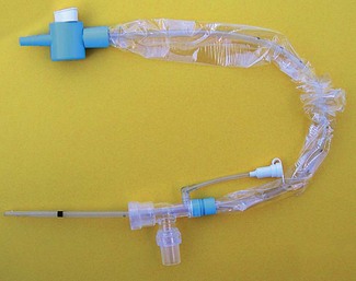
To protect staff, closed suction catheter systems are now commonly used (Fig. 20.6). The catheter is enclosed in a flexible sheath, which is permanently attached to a special 15 mm-taper adapter, which is left in circuit between the catheter mount and the endotracheal or tracheostomy tube. These systems are replaced every 24 h or as specified by the manufacturer.
Local vacuum units
Piped vacuum systems are now installed in most hospitals. The ‘behind the wall’ equipment and terminal outlets are described in Chapter 1. Medical suction apparatus may be connected into this system, wherever there is a terminal outlet.
There are two main types of ‘local’ apparatus:
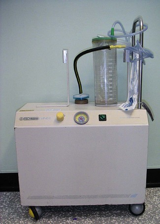
1. Free-standing floor units, mains electricity powered and often with two collection vessels used for surgical purposes in the operating theatre (Fig. 20.7). Small, ‘low-suction’, low displacement units are also available for bedside use for intracavitary and continuous wound drainage. Generating typically 5–50 mmHg sub-atmospheric pressure, these devices are usually mains and rechargeable battery-powered piston pumps.
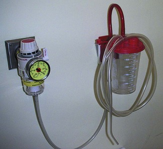
2. Wall-mounted units are local suction controllers for connection to central piped vacuum source (see Chapter 1). These have a single collection vessel as shown in Fig. 20.8. There are two types of controller: conventional ‘high-suction’ and also ‘low-suction’. Low-suction controllers are deliberately limited to provide safe suction for intra-pleural drainage or nasogastric suction. Confusion between the two types of suction controller can have disastrous consequences, hence the resurgence of free-standing ‘low-suction’ units.
Choice of suction apparatus
• Must it be portable? If so, should it be hand/foot operated (Fig. 20.9)? If not, should it be powered by electricity (mains or battery) or is pipe-line vacuum available? Could it be powered from a gas cylinder using a Venturi injector?
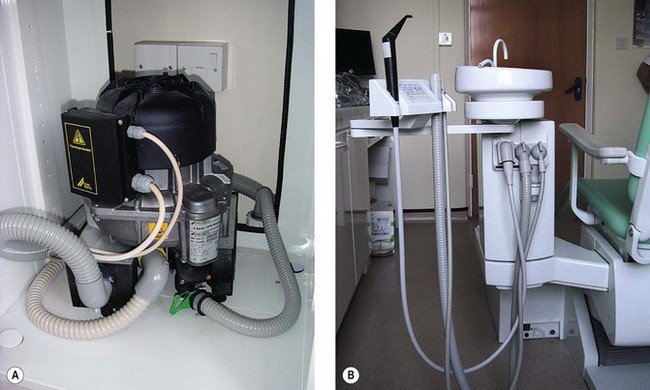
High-volume aspirators, as used in dental surgery, use a pump similar to that used in a vacuum cleaner (Fig. 20.10A). They usually have several suction tubes of different diameters for different applications (Fig. 20.10B). These tubes and their nozzles should never be obstructed, as a high flow of air is required to cool the motor, which would otherwise overheat. This type of high-flow suction is needed in dental surgery to aspirate the spray of water used to cool the tooth during high-speed drilling.
2009 Medical Suction Equipment. Electrically powered suction equipment. Safety requirements. BS EN ISO 10079-1. London: British Standards Institute, 2009.
2009 Medical Suction Equipment. Manually powered suction equipment. BS EN ISO 10079-2. London: British Standards Institute, 2009.
2009 Medical Suction Equipment. Suction equipment powered from a vacuum or pressure source. BS EN ISO 10079-3. London: British Standards Institute, 2009.
2006 HTM 02-01. Medical Gas Pipeline Systems. Department of Health Estates and Facilities Directorate. London: The Stationery Office, 2006.
[/level-membership-for-anesthesiology-category][not-level-membership-for-anesthesiology-category]
Chapter 20 Medical suction apparatus
Main components
The main components of a medical suction system are:
The schematic drawings in Fig. 20.1 outline the methods used in suction apparatus, using internationally agreed symbols.
Energy source
Suction apparatus requires an energy source that generates a sub-atmospheric pressure. This is colloquially referred to as a vacuum source, despite the fact that a true (high) vacuum is rarely achieved. In fact, the pressure required is only a maximum of 60 kPa less than the normal environmental pressure (see Further reading).
Vacuum source
The sub-atmospheric pressure required may be generated by:
• an electric motor or other source of rotational energy that may be used to drive a mechanical pump, various forms of which are shown in Figs 20.2A–E.
• pneumatically driven pumps that usually work on the Venturi principle (Fig. 20.2F). The driving force may be air, oxygen, steam or water
• a manually (or foot) operated spring-loaded bellows arrangement with unidirectional valves (Fig. 20.2G).
Pump types
Fig. 20.2A shows a piston pump, which is capable of creating high vacuum but, in transportable models, has a relatively low displacement (i.e. can only sustain low flow rates). Fig. 20.2B shows a diaphragm pump, which is a variation of the piston pump. It is mechanically simpler but is also frequently much noisier. One reason for the increased noise is that often, rather than using a conventional rotating electric motor, a much simpler large electromagnet displaces the diaphragm. Fig. 20.2C shows a form of rotary pump that can produce a high vacuum without conventional one-way valves. Fig. 20.2D shows a rotary pump capable of producing very high flows, as would be required in a dental surgery. It works in the same way as a vacuum cleaner and has the disadvantage of being extremely noisy. Fig. 20.2E shows a pump that works on the principle of the Archimedean screw. This type of pump can produce a high vacuum for a comparatively small size of machine. Fig. 20.2F shows the principle of a Venturi pump which makes use of the Bernoulli effect. Compressed fluid (gas or liquid), passing through a narrow orifice, creates a region of negative pressure beyond that orifice, which can be used to entrain adjacent air/debris. The main disadvantage of this simple affair is that it uses and is thus wasteful of large volumes of driving fluid, which is usually oxygen from cylinders. However, it does have the virtue of being extremely portable (Fig. 20.3). Finally, Fig. 20.2G shows a simple bellows mechanism with a pair of one-way valves, as would be used in manually operated suction apparatus.
