[level-membership-for-anesthesiology-category]
Chapter 4 The anaesthetic workstation
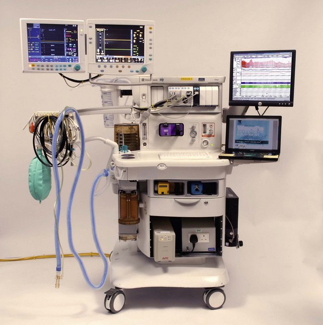
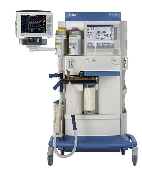
The anaesthetic workstation (Fig. 4.1) has evolved over the years from the simple inhaler for the admixture of volatile anaesthetics, through anaesthetic machines with calibrated delivery of inspired agents to the current modern workstation complete with integral ventilator, breathing system and patient and machine monitoring. Automated record keeping systems allow integration of the machine into institutional information networks and, more recently, online access to expert systems for decision support (see Chapter 22, Information Technology and the Anaesthetic Workstation). Such systems remain rare and in spite of the diminishing costs and expanding capabilities of electronic-microprocessor-based control systems, simple pneumatic anaesthetic machines with needle-valve flowmeters and conventional vaporizers still dominate in UK hospitals. There has been no ‘revolution’ in anaesthetic machines as yet.
Products offered to a market place by successful companies reflect a balance of technology, economics and what the end user is or will be willing to engage with. In this respect the particular machines described in the latter section of this chapter when viewed as a whole, demonstrate how anaesthetists have only gradually come to be prepared to use ‘fly by wire’ technology: electronically controlled machines operated through a computer interface. Even within anaesthesia such technology is not new; along the way machines with iterations of such technology such as the Engstrom Elsa1 have perished in the market where the devices really were ‘before their time’.
When the anaesthetic machine appears a physically, if not intellectually, impenetrable box with opaque control systems operated through a simple video screen, it is tempting to think that the study of joints in metal tubing, pressure regulators, mechanical hypoxia prevention systems and flow valves is somewhat anachronistic. It may be, but caution is advised: the user manual for a state of the art workstation such as the Dräger Zeus runs to 346 pages (it is difficult to envisage more than a singular instruction sheet for the original Boyle’s trolley) and reflects the complexity of the processes underlying these devices. The logic and control of such systems is an elaboration of what has gone before and an understanding of the processes is necessary if we are to be able to cope with the machines and to demand better performance or deal with fault conditions. Additionally it seems we are occasionally required to relearn lessons of the past.2
Throughout the changes above, developments have been driven by the need for safety addressed by the inclusion of fail-safe systems, and by ‘the designing out’ of the possibilities of dangerous user errors. This aspect of the workstation may be regarded as having developed through successive generations of improvements and modifications having been incorporated, such that the ‘anaesthetic machine’ component of a modern workstation is still usually recognizable as a descendant of the first-generation Boyle’s trolley. Over time, technological safety features have become enshrined in national and international standards which are largely adhered to. As such, an analysis of critical incidents may help to inform a logical approach to the understanding of the safety features and design of modern machines, and for this reason such a section is included in this chapter.
One notable change over the last few years has been the narrowing gap between anaesthesia ventilators and intensive care ventilators. Software-driven, electronically controlled devices are seen that, if not identical in technology to the ITU types, are at least capable of emulating most ventilatory modes if desired. Simple purely mechanical ventilators are seen now only in devices purpose built for the developing countries (see Chapter 27). The reader is referred to Chapters 9 and 10 for more detailed information on ventilators.
Functions of the modern workstation
• Safe provision, selection and delivery of anaesthetic gasses and vapours together with an appropriate built-in breathing system, usually a circle system
• Provision of back-up supplies of gasses in the event of failure of the primary sources
• Respiratory support in the form of sophisticated automatic ventilators capable of managing the full range of patient needs
• Monitoring of machine function and settings
• Monitoring of patient physiological variables
• Automated archived record keeping (or at least the facility to output monitored parameters to other systems) and ideally on-line access to information and administration networks
• The integration of the display and auditory signalling of monitored modalities
• Provision of appropriate connection to an anaesthetic gas scavenging system
• Provision of medical vacuum via a suction regulator
• Provision of supplemental oxygen using an auxiliary O2 flowmeter (for reduced risk of inadvertent anaesthesia)
• Work surface and storage facility for ‘everyday’ items
• Provision of mains electricity sockets for low-consumption items used in association with delivery or monitoring of anaesthesia, e.g. syringe pumps. (international standards preclude the powering of one medical device from another. For the purpose of this standard, the workstation is seen as a resuscitation trolley.)
Development of the anaesthetic workstation
Integrated and modular designs
• a circle breathing system and usually a ‘bag in bottle’ arrangement to separate respiratory gasses from the usually pneumatically driven ventilator (see Dräger Zeus for an alternative configuration)
• a choice of ventilator, often a single design but software driven and available in a variety of software configurations
• usually one of a choice of back bar vaporizer attachment systems, i.e. Selectatec or Dräger, allowing vaporizers to be exchanged for a choice of volatile agent; however, some newer electronically controlled machines utilize their own proprietary systems for volatile agent dosing (see later)
• a patient monitor of choice, itself often of a modular design where individual parameters can be ‘hot swapped’, i.e. exchanged whilst actually in use
• an archived/networked or stand alone anaesthesia record system if so desired
Electronics: monitoring or control?
The flow of gasses through the workstation has largely remained under pneumatic and direct mechanical control. There are currently only very few machines offering electronic servo control of gas flow and/or vapour concentrations. Although needle valves (see below) remain ubiquitous for control of gas flows, many machines do use electronic monitoring (and display) of the flow rates instead of rotameters (see Chapter 2).
The anaesthetic delivery system
A typical machine consists of:
• a rigid metal framework on wheels; attached to this is a source of compressed gas consisting of a pipeline system and/or metal cylinders containing the relevant gasses
• pressure regulators for reducing the high pressures in the attached cylinders to machine working pressures of approximately 420 kPa (60 psi) or 310 kPa (45 psi) in some countries. (The British Standard stipulates 420 kPa which is 61.3 psi. For convenience this has been rounded off to 60 psi)
• secondary regulators for damping surges in machine working pressure (see below)
• pressure gauges to show pipeline and cylinder pressures
• a method of metering (e.g. flowmeters), using adjustable valves for proportioning and mixing the various gasses
• a system for attaching vaporizers to the anaesthetic machine for the addition of volatile anaesthetic agents to the gas mixture
• a safety mechanism to warn of the failure of the oxygen supply and to prevent hypoxic mixtures of gas/vapour reaching the patient (oxygen failure warning device)
• a safety mechanism for releasing high-pressure build-up of gasses (back bar pressure relief valve) should a fault occur in the machine
• a system that bypasses the flowmeter for the administration of a high flow of pure oxygen in an emergency
• in-built connection to a circle breathing system with the facility to switch to a single outlet for delivering the gasses and vapours to any other breathing system (the common gas outlet).
The compressed gas attachments
Cylinders
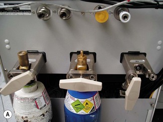
The cylinders are clamped onto the machine by a yoke arrangement and secured tightly using a wing-nut (Fig. 4.2). To prevent installation of the wrong gas cylinder to a yoke, the cylinder heads are coded with appropriately positioned holes that match pins on the machine yoke. This is called a pin index system, for which there is an internationally agreed standard (ISO 407:2004) (see Fig. 1.5). A thin neoprene and aluminium washer (Bodok seal) is interposed between the cylinder head and yoke to provide a gas-tight seal when the two are clamped together.
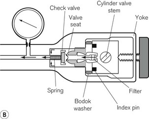
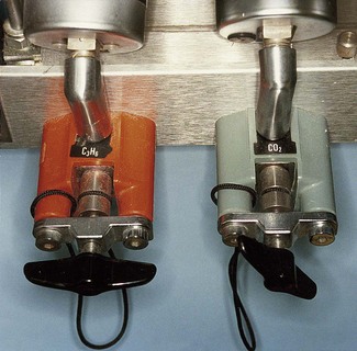
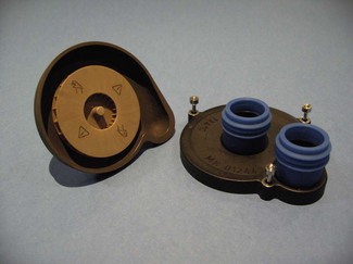
A leak of not more than 15 ml min–1 through an open yoke is acceptable in new machines. However, in older machines the non-return valve may not be as efficient owing either to the design (the valve not being spring loaded) or to wear and tear, and could result in greater than acceptable backpressure leaks. These leaks, when occurring unexpectedly, have been shown to alter the composition of the gas leaving the flowmeter block and have resulted in the delivery of a hypoxic gas mixture to an attached breathing system (see section on Flowmeters). Blanking plugs (dummy cylinder heads) are available and should be inserted into all empty yokes to overcome this problem (Fig. 4.3).
Pipelines
Each pipeline source is attached to the machine via a gas-specific connection. In the UK this is called a NIST (non-interchangeable screw-threaded) connection and is discussed in greater detail in Chapter 1 (see Fig. 1.29). In the USA, a similar system is employed called DISS (Diameter Indexed Safety System). However, the diameters of the nipples and bodies for the various connections are smaller and not compatible with the NIST system.
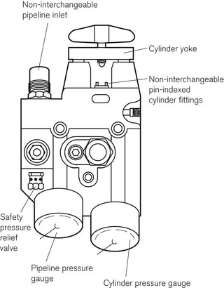
Pressure (contents) gauges
The pressure in cylinders and pipelines is measured by Bourdon-type gauges (see Fig. 2.6). The gas entry to the pressure gauge has a constriction so as to smooth out surges in pressure that could damage the gauge, as well as to prevent total and rapid loss of gas should a gauge rupture. The gauges are labelled and colour coded for each gas, according to the standards for each country. They are also calibrated for each gas used on the machine. The scale on the gauge extends to a pressure at least 33% greater than either the filling pressure of the cylinder or pipeline pressure (at a temperature of 20°C). Each cylinder yoke may be fitted with a gauge or, alternatively, a single-cast brass block may be used to house the NIST/DISS pipeline connection, cylinder yoke, pressure regulator and housings for the pressure gauges (Fig 4.4). This minimizes the number of connections and potential leaks, but is a somewhat dated arrangement now.
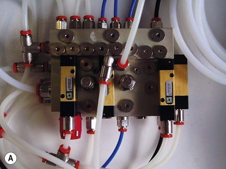
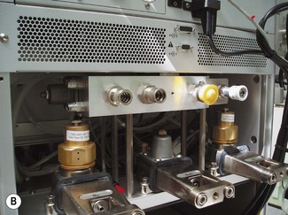
Single-block manifold
The single-cast brass block has given way in recent years to the single-block gas manifold (Fig. 4.5), which is drilled to accommodate as many as possible of the gas pipeline and pneumatic valve interconnections. The small, compact manifold (Fig. 4.5A), for reasons of design economy, does not carry the cylinder yokes and is hence typically downstream of the primary pressure regulator which is invariably part of the cylinder yoke assembly (Fig. 4.5B).
Pressure regulators (reducing valves)
Pressure regulators are used on anaesthetic machines for three main reasons:
1. The pressure delivered from a cylinder is far too high to be used with safety in apparatus where a sudden surge of pressure might accidentally be delivered to the patient.
2. If the pressure were not reduced, flow-control (fine-adjustment) valves, tubing and various other parts of the apparatus would have to be much more robust, and a fine and accurate control of gas flow would be difficult to achieve. There would also be a danger of pressure building up and damaging other components of the apparatus.
3. As the contents of a cylinder are exhausted, the pressure within the cylinder falls. If there were no regulating mechanism to maintain a constant reduced pressure, continual adjustment would have to be made of the flow-control valve in order to maintain a given flow rate.
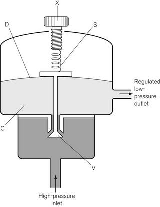
Working principles
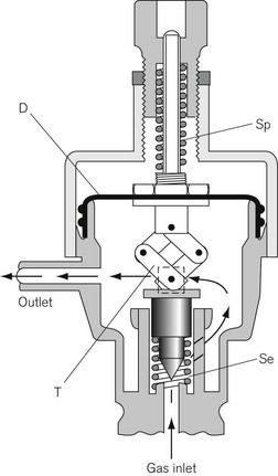
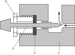
In Fig. 4.6, the chamber C is enclosed on one side by the diaphragm D. As gas enters the chamber through the valve V, the pressure in the chamber is increased and the diaphragm is distended against its own elastic recoil and the force from the spring S. Eventually the pressure rises high enough to move the diaphragm far enough to close valve V. The pressure at which this occurs may be varied by adjusting the screw X so as to alter the force exerted by the spring S. If gas is allowed to escape from the outlet of the chamber, the pressure falls and valve V reopens. When the regulator is in use, a steady pressure is maintained in the chamber by the partial opening of valve V.
In another form of regulator (Adams valve), the push-rod is replaced by a ‘lazy tongs’ toggle arrangement (Fig. 4.7), which reverses the direction of the thrust transmitted from the diaphragm.
The accuracy of regulators
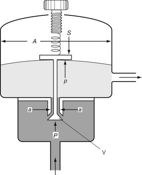
Let us consider that the push-rod is pushed downward by two forces: the compression in the spring and the elastic recoil of the diaphragm (Fig. 4.8). Let these be added together and represented by S. The force that opposes S consists of two parts: the high pressure (P) of the gas pushing on the valve V over an area of a; and the low pressure (p) acting on the diaphragm over an area A, so:

In the Adams valve (Fig. 4.9), it can be seen that the pressure P exerted by the high-pressure gas to open valve V is assisted by the spring and the recoil of the diaphragm S. These forces jointly oppose the force exerted by the low-pressure gas on the diaphragm, so:
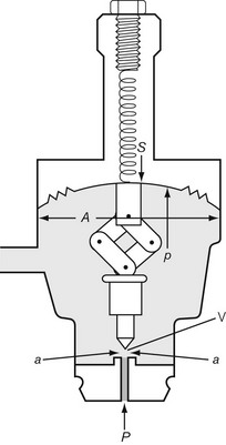

Now as P falls, so does p; therefore the regulated pressure falls slightly as the cylinder pressure drops. At the same time the valve V opens slightly and this, by allowing the spring to expand, reduces S, which slightly accentuates the fall in p. The fall of p can be minimized by making S great compared with Pa.
There are several types of pressure regulator available, the choice being dependent on:
Interchangeability of regulators
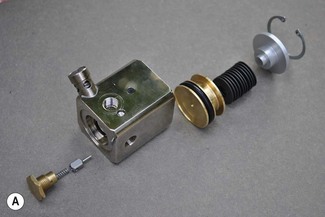
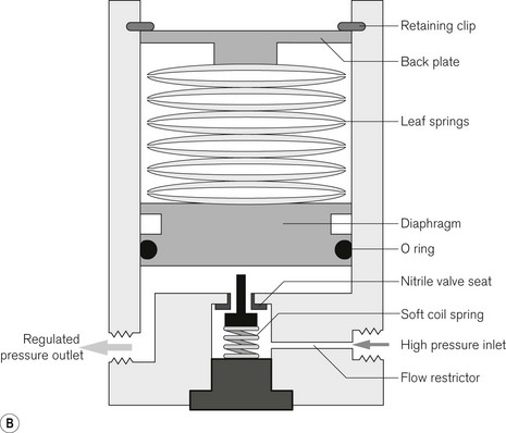
Pressure regulators used to be labelled and coded for specific gasses. This is because a special alloy was required in the valve seating for some gasses (e.g. nitrous oxide) in order to prevent corrosion. However, modern regulators are designed to be compatible with all anaesthetic gasses. This is achieved by using materials such as PTFE coatings on the diaphragms together with nitrile (a hard synthetic rubber) valve seats and chrome-plated brass for the regulator body (Fig. 4.10). These too are described as ‘universal’ by their manufacturers.
Common faults in regulators
• Damage to the soft seating of valves may occur as a result of the presence of grit or dust, usually from a dirty cylinder. This may cause a steady build-up of pressure in the apparatus when the cylinder is left turned on but with no gas flowing.
• A hissing noise may indicate a leaking or burst diaphragm. The regulator will need replacing or repairing by the manufacturer or service engineer.
• Adams valves sometimes develop a fault that causes continual ‘jumping’ of the flowmeter bobbin, indicating an intermittent change of pressure and flow rate. This is usually due to the ‘lazy tongs’ sticking as a result of wear, but it may also be caused by small particles of grit or metal in the lazy tongs or the valve seating.
Relief valves on regulators
Safety blow-off valves are often fitted on the downstream side of regulators to allow the escape of gas if, by accident, the regulators fail and allow a high-output pressure. With a regulator designed to give a pressure of 420 kPa (60 psi), the relief valve may be set at 525 kPa (70 psi). These valves may be spring loaded (Fig. 4.10), in which case they close when the pressure falls again, or they may operate by rupture, in which case they remain open until repaired. As a further safety feature, a flow restrictor (usually in the form of a simple pin hole orifice) on the high pressure inlet side of the regulator, limits maximal flow from the cylinder to between 70 and 150 l min–1, ensuring that in the event of regulator failure the high-pressure relief valve can dump the maximal flow without further pressure rises.
Secondary pressure regulators
Several factors cause the machine working pressure (420 kPa in the UK) to fluctuate by up to 20%. For example, at times of peak demand in a hospital, pipeline pressures may well drop by this amount. Similarly, if an auxiliary outlet on the anaesthetic machine is used to drive a ventilator with a very high sudden and intermittent gas demand, a similar pressure drop will occur before the pipeline or cylinder is able to restore the supply. These pressure fluctuations produce parallel fluctuations in flowmeter performance. A second (secondary) regulator set below the anticipated pressure drop smoothes out the supply, minimizing these fluctuations. This is important in machines incorporating mechanically linked anti-hypoxia systems attached to the flowmeter bank (see below), as these systems assume that the oxygen supply pressure is constant in order to achieve an accurate flow of gas. A mechanically linked system would not be able to detect altered gas flow rates caused by changing pressures. Furthermore, secondary regulators also prolong the accurate supply of oxygen to the flowmeter if there is a gradual failure of the oxygen supply (i.e. cylinder emptying) prior to the oxygen failure warning device being activated.
Flow restrictors
It was an occasional practice to entirely omit regulators from the pipeline supply (420 kPa (60 psi)) in older anaesthetic machines. Sudden pressure surges at the patient end of the anaesthetic machine were prevented by flow restrictors. These consisted of constrictions in the regulated pressure pipework upstream of the flowmeters. The disadvantage of using flow restrictors without regulators was that changes in pipeline pressure were reflected in changes of flow rate, which made readjustment of the flow control valves necessary. Also, there was a danger that if there was an obstruction at the outlet from the anaesthetic machine, pressure could build up in the vaporizers and cause damage. This was normally prevented by the inclusion of a ‘blow-off’ safety valve (see section on ‘the back bar’ below). Flow restrictors do not normally require any maintenance.
Gas-tight connections within the machine
Whilst there is no standard for the design of gas piping within the machine, with the advent of nylon tubing, manufacturers tend to use pipes of differing diameters and/or sometimes colour for the different gasses to reduce the risk of accidental misconnection during servicing and assembly (see Fig 4.5A where the white tubing is for oxygen and the blue and black, respectively, for nitrous oxide and air).
Joints in metal tubing
1. One pipe may have a slightly larger diameter than the other so that they overlap (Fig. 4.11A).
2. Where the diameters are similar, both ends are inserted into a sleeve of metal (Fig. 4.11B).
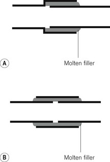
The adjacent surfaces are then bonded together by brazing (applying a molten filler alloy whose melting temperature is above 430°C) or hard soldering (a similar principle using an alloy with a lower melting point). After making such a joint it is important that all traces of flux are removed. Flux is a material applied to the surfaces to be bonded, allowing the molten filler to spread more evenly. More recently, a system of brazing copper pipes and brass fittings without flux has been evolved. This is used particularly for medical gas pipeline installations.
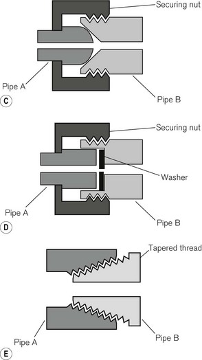
Where provision has to be made for disconnection and reconnection of a joint, a union is used. This consists of two parts held together in a gas-tight manner, usually by a nut or cap, which screws onto a parallel male thread. Figure 4.11C shows a ball and cone (or cone seated) union, in which the seating is by direct metal-to-metal contact. A flange (or flat seated) union (Fig. 4.11D) requires a washer to complete the seal. With pipes carrying oxygen, this washer should be of non-flammable material.
For some other purposes tapered threads (Fig. 4.11E) may be used and the seal made either by screwing them down extremely tightly or by interposing a sealing compound such as PTFE (polytetrafluoroethylene/Teflon) in the form of a tape. The joint between the valve block and the body of a medical gas cylinder, for example, is sealed by a metal foil between two tapered threads and is designed to melt at high temperatures, allowing gradual release of cylinder contents.
Other detachable joints
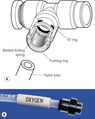
High-density nylon tubing, connected by metal junctions, is now ubiquitous in anaesthetic machines (Fig. 4.12). It is cheaper, less prone to rupture and simpler to install. Joints are made gas-tight by an ‘O’-ring fitted between the components. This consists of a simple ring made to a fine tolerance out of a material such as neoprene. It is housed in a recess in the larger component to stop it becoming dislodged.
Valve glands
Where a valve spindle passes from an area of high pressure to one of low pressure, provision must be made to prevent the leak of gasses along the line of the spindle. This is achieved by means of a gland. In Figure 4.13, the nut ‘N’ must be screwed down sufficiently tightly to ensure that the packing is applied so closely to the spindle that no gas can escape by this route. There is provision for the nut to be tightened down further to prevent leaks as the packing wears.
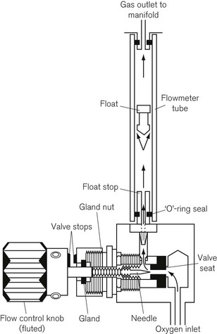
The principle can be used for a high-pressure gland, such as that of an oxygen cylinder (see Chapter 1), or in a low-pressure gland such as that in a flowmeter (Fig. 4.14). In the case of high-pressure valves, a special type of leather or long-fibre asbestos was at one time used for the packing, but modern glands are filled with specially shaped nylon. Those in low-pressure flow control valves may be filled with rubber, nylon, neoprene or cotton.
‘O’-rings
In certain circumstances, the packing of a stuffing box may be replaced by an ‘O’-ring (Fig. 4.12A). If the valve spindle S and the casing C are suitably designed, an ‘O’-ring is all that is required to prevent leakage at this point. ‘O’-rings can withstand remarkably high pressures and yet cause very little friction between the spindle and the casing.
Flowmeters (rotameters)
Gas at a suitably regulated pressure from either a pipeline supply or cylinder, is passed through a flowmeter, which accurately controls the flow of that gas through the anaesthetic machine. The anaesthetic machine conventionally has a bank of flowmeters for the various gasses used (Fig. 4.15). Flowmeters are described briefly here, but more detailed information can be found in Chapter 2.
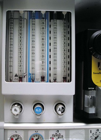
Figure 4.15 A flowmeter bank. Note the ‘cascade’ flowmeters for all gasses and the protrusion of the O2 control valve.
A typical flowmeter assembly (Fig. 4.14) consists of:
1. The torque (twisting force) required to operate them must be high enough to minimize accidental readjustment (this torque can be adjusted by the manufacturer by varying the degree of tightness of the gland nut, although these may work loose during frequent use).
2. Values must be accurate to within 10% of the indicated flow (at flow rates between 10% of full scale or 300 ml min–1, whichever is the greater, and 100% of the maximum indicated flow).
3. When axial push or pull forces are applied to the valve spindle without rotation (at a flow rate 25% of the maximum indicated flow), the maximum flow change must not be greater than 10% or 10 ml min–1, whichever is the greater. (Much older machines may have spindles that do not meet this requirement. Axial pressures at a flow rate of 1 l min–1 have been shown to change the flow rate by 50% in these machines, with resultant hypoxic mixtures being delivered to the patient, when they are used with a low-flow anaesthetic breathing system.)
4. Each flow control valve must be permanently and legibly marked, indicating the gas it controls (using the name or chemical symbol).
5. As well as conforming to (4), the oxygen flow control knob (Fig. 4.14) must have an individual octagonal profile. When the valve is closed the knob must project at least 2 mm beyond the knobs controlling other gasses at all flow rates. Its diameter must also be greater than the maximum diameter of the flow control knobs for other gasses.
The flowmeter block
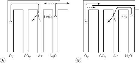
The flowmeters are mounted vertically and usually next to each other, in such a way that their upper (downstream) ends discharge into a manifold. Traditionally, this was unfortunately arranged in such a way that if there were a leak in, say, the central tube, oxygen would be lost rather than nitrous oxide. As a result, a hypoxic mixture could be delivered to the patient (Fig. 4.16A). In most modern machines, oxygen is the last gas to flow into the manifold so that a leak would not lead to such a hypoxic mixture (Fig. 4.16B). As a solution to the same problem, in some countries such as the USA and Canada, the order of the flowmeters in the block has been reversed, with oxygen on the right. However, this too has previously (before the advent of hypoxic guard interlinks) led to patients receiving a hypoxic mixture because anaesthetists have not been made aware of the transposition.
The practice of removing carbon dioxide cylinders (and in the past cyclopropane) from their yokes has exposed a further hazard in older machines. Oxygen can be lost via a retrograde leak through a carbon dioxide (or cyclopropane) flowmeter, even when intact, if the corresponding needle valves are inadvertently left open. Gas can track back from the manifold via the flowmeter and open needle valve to the unblocked cylinder yoke and escape. The one-way (check) valves fitted to cylinder yokes in some machines were never intended to provide a perfect gas-tight seal under all conditions. They were not spring loaded because they were designed to work against high back pressures rather than the relatively low back pressures produced in the retrograde leak. This leak may be increased by adding an extra resistance to flow downstream of the flowmeter block (i.e. some types of minute volume divider ventilator or high-resistance vaporizer), which effectively increases the gas pressure in the flowmeter block. All empty cylinder yokes for air, carbon dioxide and cyclopropane (where these still exist) should be fitted with blanking plugs (Fig. 4.3) so as to prevent this problem. Modern standards (BS EN 740:1999) stipulate that a maximum retrograde flow of 100 ml min–1 is acceptable, or 10 ml h–1 if the fault condition causing this is not alarmed.
Recent increased interest in low-flow anaesthesia systems has created a demand for flowmeters that can more accurately measure flows below 1 l min–1. This is achieved by the use of two flowmeter tubes for the same gas. The first is a long thin tube accurate for flows from 0 to 1000 ml min–1 that complements the second conventional tube calibrated for higher flows (1–10 l min–1 or more). Both are activated from the same flow control valve. These ‘cascade’ flowmeter tubes for each gas are arranged sequentially (Fig. 4.15) so that when the flow control valve is opened the low-flow tube is seen to register first. At flows over 1 l min–1, the bobbin in the low-flow tube is no longer easily visible.
Anti-hypoxia devices
Mechanical devices
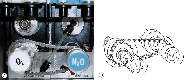
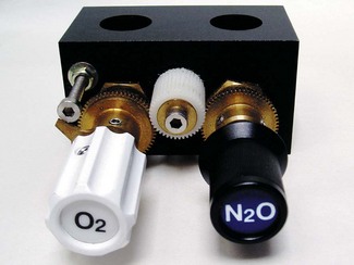
The ‘Link 25’ system (Ohmeda) (Fig. 4.17) incorporates a chain that links the flow control valves for nitrous oxide and oxygen. There is a fixed sprocket (cog) on the nitrous oxide spindle that relays its movement to a larger cog on the oxygen flowmeter spindle via a chain. The oxygen cog moves along a static, hollow worm gear, through which the oxygen flowmeter spindle passes. As the nitrous oxide flowmeter control is turned counter-clockwise (increasing the nitrous oxide flow), the chain link moves this larger cog nearer to the oxygen flowmeter control so that, when a 25% oxygen mixture is reached, it locks on to the oxygen control knob and moves it synchronously with any further increase in nitrous oxide flow. The oxygen flow control can of course be independently opened further, but cannot be closed below a setting that if nitrous oxide is flowing, will produce less than 25% oxygen in the mixture. Other manufacturers use interlinking gears (Fig. 4.18) to achieve the same effect. This type of mechanical link, however, has some limitations:
• It takes no account of other gasses in the flowmeter block (air and carbon dioxide) that could potentially dilute the mixture below a 25% oxygen concentration.
• On its own it will not recognize and compensate for variations in gas supply pressure that affect flowmeter performance. However, these systems include secondary pressure regulators (see above) in both the oxygen and nitrous oxide systems, the purpose of which is to prevent variations in gas supply pressure from affecting flowmeter performance.
• At low fresh gas flows into a circle system, a 25% oxygen ratio may be insufficient to prevent the circle patient gas mixture from becoming hypoxic (see Fig. 5.22). Hence a minimum basal flow of oxygen (see below) or a 50% oxygen ratio at low flows is required.
A further safety feature of this system includes a mechanical stop fitted (Fig. 4.18) to the oxygen flowmeter control valve, ensuring that a preset minimum standing flow (typically between 25 and 250 ml min–1) of oxygen is maintained even when the valve is fully closed. This flow, of course, can occur only when the machine master switch for all the gasses is switched on.
Pneumatic devices, e.g. Pneupac ratio system
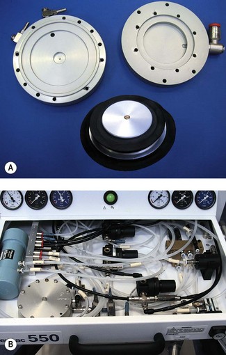
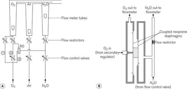
Originally designed and launched by Medical and Industrial Equipment Ltd UK (MIE) in 1988, this system relies on a ratio mixer valve (Fig. 4.19) to ensure that the oxygen concentration leaving the flowmeter block never drops below 25% of the nitrous oxide concentration. When the machine master switch is turned on, a basal flow rate of 200–300 ml min–1 of oxygen is established (Fig. 4.20A). This is independent of, and bypasses, the ratio mixer valve. Nitrous oxide supplied to one side of the valve exerts a pressure on the diaphragm which is opposed by the pressure exerted by oxygen on a separate but coupled larger diaphragm (Fig. 4.20B). Inward movement of the oxygen diaphragm is linked to the opening of a poppet valve that allows more oxygen to flow through the O2 chamber thus balancing the opposing forces. Any increase in the flow of nitrous oxide results in an increase in pressure on the nitrous oxide side of the diaphragm, causing the latter to move towards the compartment containing oxygen. The ratio of the area of the diaphragms is so constructed that the oxygen flow rate will increase by a ratio of 25% of any increase in the nitrous oxide flow rate. This increased oxygen flow is independent of the main oxygen flow control valve that bypasses the ratio mixer valve and, of course, can be adjusted independently. The ratio mixer valve does not work in reverse as it takes a single passive N2O connection from downstream of the N2O flow control valve whilst taking O2 from upstream (before) of the O2 flow control valve; hence, if the nitrous oxide flow rates are reduced, the oxygen flows remain as set before by the O2 flow control valve. The double diaphragm arrangement also means that rupture of a diaphragm will not result in contamination of the O2 flow by N2O.
The back bar
The vaporizers are mounted, either singly or in series, along the back bar, downstream from the flowmeter block. Traditionally, vaporizers were bolted onto the back bar and linked to each other by tapered fittings. The various manufacturers employed different sizes of tapers and mounting positions but these were superseded by the provisions of BS 3849 (UK), which recommended 23 mm ‘cagemount’ tapers. (The term cagemount originally refers to a type and size of tapered connection for a reservoir or rebreathing bag that has a small wire cage fitted to its inlet to prevent the neck of the bag from being obstructed, when the latter is empty and collapsed. The cagemount taper for vaporizers, though no longer used in the West, is still in use in many parts of the world.)
The Ohmeda ‘Selectatec’ System
Each Selectatec station on the back bar has two vertically mounted male valve ports (Fig. 4.21). Between these inlet and outlet ports is an accessory pin and a locking recess. The matching vaporizer assembly has two female ports between which there is a locking assembly and a recess to accommodate the pin. The vaporizer is lowered on to the male valve ports and the locking knob is turned to fix it into the recess on the back bar (Fig. 4.21A). Successive generations of GE /Ohmeda vaporizers are labelled sequentially and, although the essential design of the back bar mounting system has not changed, the accessory pin has been added to prevent use of Tec 3 and previous generations on the modern back bar (see below).
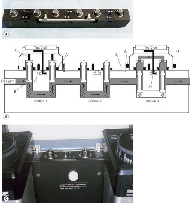
Figure 4.21 A. A three-station ‘Selectatec’ back bar (viewed from behind). B. Schematic diagram showing a TEC 5 vaporizer attached at station 1 and switched OFF, an empty station 2 and a TEC 5 attached at station 3 but switched ON. A, ‘O’-ring seal; B, valve; C, TEC 3 lock-out pin; D, recess for vaporizer lock; E, safety interlock; F, recessed spindles in the vaporizer; G, immobilizer rod; H, back bar lock. C. A three-station back bar showing the safety interlock mechanism.
‘O’-rings on the male valve ports ensure a gas-tight fit. The two female ports on the vaporizer have recessed spindles (TEC 4 and above) that, when the vaporizer is switched on, protrude through the gas-tight seals of the male valve ports on the back bar. The ball valves (which provide the seals) in the male ports are displaced downwards occluding the back bar, and gas from the back bar is diverted into the vaporizer (Fig. 4.21B, station 3). TEC 3 vaporizers had fixed spindles that automatically depressed the ball valves in the male valve ports when the vaporizer was lowered on to the back bar assembly. Gas, therefore, passed through the head of the vaporizer even when it was not switched on or even locked on. This arrangement obviously had a greater potential for gas leaks and has been modified by the retractable spindle assembly on the TEC 4, 5, 6 and 7.
These models also incorporate a ‘safety interlock’. This consists of an extension rod that protrudes sideways from a vaporizer as it is turned on, and displaces the equivalent rod on the vaporizer beside it, preventing the latter from being switched on. On a three-station back bar, there is a plastic lever (Fig. 4.21) linking stations 1 and 3. Should station 2 be empty, the lever links the extension rods between vaporizers 1 and 3 to ensure that only one vaporizer can be turned on at any one time. Tec 3 vaporizers had no safety interlock and this is yet another reason for their use being precluded by the fitting of the accessory pin. Presently machines are rarely specified with a three station back bar and this plastic lever is seldom required.
Dräger Interlock 2
The mounting system is similar to the ‘Selectatec’ version, although the dimensions are unique. The mounting system also includes an interlock preventing the administration of more than one vapour with a selector lever that locks one vaporizer at a time (Fig. 4.22). Dräger vaporizers are also available with Selectatec and other fittings.
Problems with detachable vaporizer systems
Removable vaporizer systems generate specific problems:
• As mentioned above, there is a greater potential for leaks.
• The vaporizer may be accidentally dropped and damaged in transit to or from the back bar.
• Tipping of older models of vaporizer in transit could result in liquid agent entering the bypass system causing either liquid or high concentrations of vapour to be present in the breathing system.
• Also, in countries where trichloroethylene is still used, a vaporizer containing this agent may accidentally be attached to a back bar station in a position that results in the vapour being passed into a breathing system containing soda lime. Trichloroethylene is known to react with warm soda lime to produce substances that are neurotoxic if inhaled.
Back bar working pressures
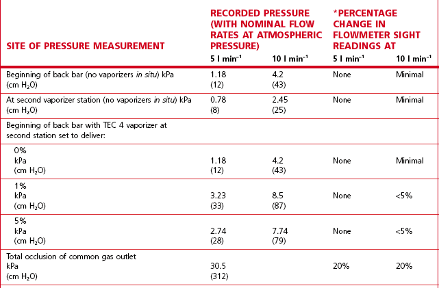
The flowmeter tubes in the flowmeter bank have, as a rule, been calibrated for gas flows assuming no downstream resistance. In a traditional back bar (23 mm internal diameter system) with the vaporizers switched off, the wide bore of the gas passages offers minimal flow resistance and so the back bar pressure developed at conventional flow rates (5–10 l min–1) is marginally above atmospheric pressure. However, many modern back bars have narrow bore (8 mm) gas passages, which increase flow resistance and thus back-pressure on the flowmeters. The addition of high-resistance vaporizers and minute volume divider ventilators, which cause a build-up of pressure in the fresh gas flow (see Chapter 9, Automatic ventilators), increases back bar pressures. Table 4.1 shows typical back bar pressures developed and percentage changes in flowmeter settings with the ‘Selectatec’ back bar with and without a high-resistance vaporizer fitted. It should be noted that the small decreases in the flowmeter indications produced does not mean a decrease in the flow of gas to a patient. It is merely that the gas is compressed at the higher pressures and subsequently re-expands downstream when the various resistances have been overcome. Readjustment of the flowmeters to the original settings following an induced pressure rise would therefore be inappropriate.
Additional safety features
Several safety features are installed either on or downstream of the back bar:
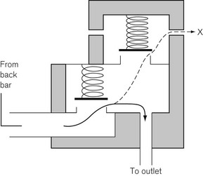
• Intermittent back-pressure surges from certain minute volume divider ventilators can adversely affect vaporizer performance (see Chapter 3), and so most machines employ a spring-loaded non-return valve in the system to prevent these surges reaching the vaporizers.
• Since high-pressure build-up in the back bar can damage flowmeter and vaporizer components, a pressure relief valve (commonly set at 30–40 kPa) is fitted. This is often fitted in the same housing as the non-return valve (Fig. 4.23).
Emergency oxygen
A flowmeter bypass valve for an emergency oxygen supply is now fitted as standard (BS EN ISO 60601-2-13). The bypass flow joins the pipeline from the back bar just before the common gas outlet such that, when activated, it preferentially supplies oxygen at a rate of not less than 30 l min–1 into an attached breathing system. In earlier anaesthetic machines this bypass for oxygen was fitted near the flowmeter block. When it was operated, this resulted in an initial surge of gas and vapour to the patient prior to the pure oxygen being delivered.
Oxygen failure warning devices
The Ritchie whistle
The Ritchie whistle was introduced in the mid-1960s and forms the basis for most current oxygen failure devices. It was the first device to rely exclusively on the failing oxygen supply for its power. Figure 4.24 shows an oxygen failure warning device incorporating a Ritchie whistle marketed at one time by Ohmeda and still present on older machines in service.
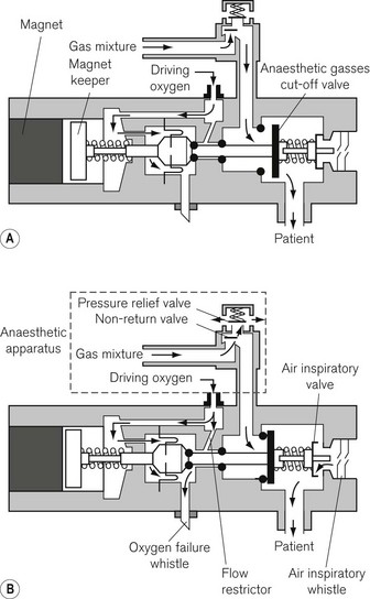
Decreasing pressure in the oxygen supply to the flowmeter block activates the valve, permitting a flow of oxygen (via the restrictor) to operate the oxygen failure whistle. The whistle sounds continuously until the oxygen pressure has fallen to approximately 40.5 kPa (6 psi). At a pressure of approximately 200 kPa (30 psi) the force of the magnet keeper return spring and the magnet causes the anaesthetic gasses cut-off valve to be closed, cutting off the supply of anaesthetic gasses to the patient. At the same time the spring load on the air inspiratory valve is released, allowing the patient to inspire room air. Whenever the patient inhales, the inspiratory air whistle sounds.
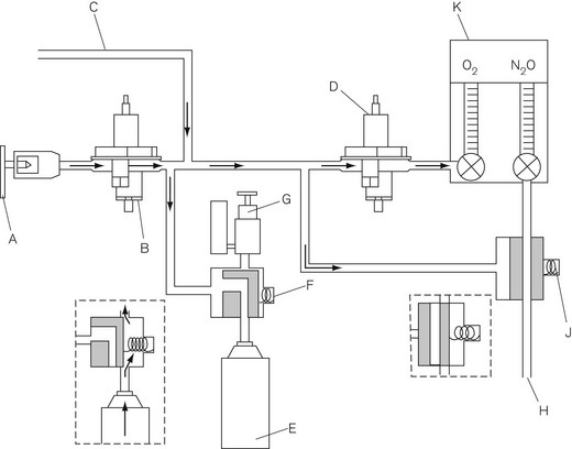
Current oxygen failure warning devices
• cut off the supply of all gasses other than oxygen, air and premixed gasses with an oxygen content above 21%(V/V) to the fresh gas outlet; or
• progressively reduce the flow of all other gasses (except air or premixed gasses with an oxygen content above 21% (V/V)) while maintaining the proportion of oxygen until the supply of oxygen finally fails, at which point the supply of all other gasses (except air or premixed gasses with an oxygen content above 21% (V/V)) shall be cut off.
Figure 4.25 shows a schematic diagram of the pneumatic arrangement for an alarm and shut off system that satisfies current standards.
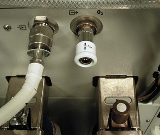
Auxiliary gas sockets
Anaesthetic machines may now be fitted with mini-Schrader gas sockets (Fig. 4.26), but only for air or oxygen. These may be used to power devices such as ventilators, gas injection systems for bronchoscopy, and suction units. The sockets should be permanently and legibly marked for their specific gasses (air or oxygen) and their working pressure of 400 kPa approximately (in the UK).
Ventilators
Automatic ventilators, including their classification and fundamental principles, are discussed specifically in Chapter 9. Ventilators for use in the Intensive Care Unit (ICU) are further considered in Chapter 10.
In order to fully separate the gasses of the pneumatically driven ventilator used by most manufacturers (there are exceptions such as the Dräger Primus and Zeus below) from the respiratory gasses of the patient, the enclosed bellows arrangement with a rising bellows is almost ubiquitous. Chapter 9 gives a detailed overview of ventilators with specific reference to the ‘bag squeezer’ type ventilators seen in modern anaesthetic workstations. The Blease900 Series ventilator (Spacelabs Healthcare) is described in detail in that chapter and gives an insight into the modern ventilators used in many anaesthesia machines.
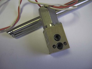
Proportional flow valves
The heart of the modern ventilator is the proportional flow valve. Proportional valves are increasingly also seen in the control of gas flow within the patient gas circuits. This type of valve allows extremely accurate and rapid control of the flow of gas from a high-pressure source. Whereas a simple solenoid valve can oscillate rapidly between on and off positions, the proportional valve is so termed because the excursion of the solenoid (and opening of the attached valve) is proportional to the voltage applied across it (Fig. 4.27). Fig. 4.28 shows a typical proportional valve. Such a valve typically allows flow rates up to 130 l min–1 with a maximal response time of less than 100 ms. In ventilators the valve is usually placed immediately downstream of a secondary regulator which supplies the drive gas to the valve at a pressure of about 2.3 bar. Manufacturers set this pressure somewhat below the minimum pressure that may be expected from gas pipelines in order to have a non-fluctuating supply pressure to the valve so that pressure/flow characteristics are predictable for the flow controller algorithm. ITU ventilators may have larger, more sophisticated proportional valves with an order of magnitude swifter response times. Massive flows can be rapidly generated on patient demand, even allowing almost seamless pressure support of spontaneous patient breathing. Downstream flow and pressure sensing permits feedback control of the flow from the valve via the microprocessor control system.
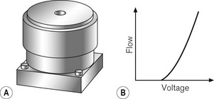
Figure 4.27 A. Representation of proportional flow valve and B. the relationship between voltage and gas flow. (Fig. 9.8A, shows the mode of operation of a typical proportional flow valve.)
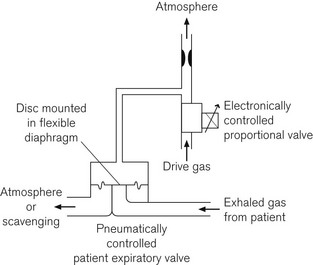
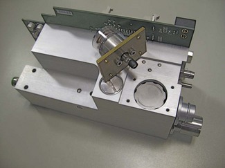
Some systems, such as the Dräger E series ventilators, use a separate or second proportional valve to control a lower pressure gas flow from which a side arm is used to pressurize the machine side of an expiratory valve for control of inspiration and PEEP or continuous positive airway pressure (CPAP) (Fig. 4.29). Alternatively this proportional valve can be of a type that operates an actuator directly onto the leaflet of the ventilator inspiratory/expiratory control valve (Fig 4.30). (See also Figs 9.8 and 9.9, solenoid driven proportional flow valve for low-pressure gas.) Note, comparing figures 4.28 and 4.30, that the valves that manage low pressure gas flows have very much larger apertures.
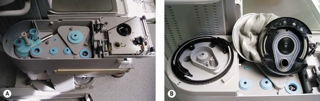
Integral breathing systems
The need to both integrate the breathing system into an ergonomic design and allow sterilization of patient gas pathways, can produce a labarynthine system with multiple parts, valves and microswitches to sense the position and function of levers and detachable components (Fig. 4.31). That in spite of such numerous parts, many of these machines cannot be misassembled and do not leak, is a testament to good engineering design. However, the potential for problems to arise in such complex devices must always be borne in mind and it is advocated that a self-inflating bag and alternative source of oxygen is always readily available (see Pre-use check below). A ‘top circuit’, such as a Mapleson C or D for attachment to the common gas outlet in times of crisis and confusion, is also extremely useful.
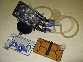
The water generated by the circle absorber system is beneficial in moisturizing the inspired patient gasses, but poses a problem for designers of anaesthesia machines particularly with the increasing use of low flow anaesthesia. Rain out or condensation of this moisture in the system can interfere with the function of the valves and flowmetering within these systems. Particular provision must be made for this, and the issue is tackled differently in the various machines by the manufacturers. This may be the use of heated patient circuit plates as in the Dräger Primus (Fig 4.32), or the use of an additional specific condenser arrangement as in the GE Healthcare Aisys (Fig. 4.33). Here this approach is coupled with flowmeters on the circle system that are modified so that water accumulation is less likely to interfere with the function of the flap valve of the differential pressure variable orifice flowmeters. In the Aestiva also by GE Healthcare the point of condensate collection is at the bottom of the absorber assembly and a drain plug is placed there (Fig. 4.34). This is a frequent source of a breathing system leak that is difficult to trace as it is not obvious when this drain plug is open.

Ergonomics
Given the many demands made of the modern workstation, as detailed above, there has to be far greater consideration given to ergonomics at the design stage. Sections of the machine should have clearly defined task orientations with tasks or modalities not divided across different areas of the machine. Modular approaches to the workstation are particularly prone to having various components fighting one another. The execution of multiple linked manoeuvres to achieve a single functional change in the machine settings (e.g. having to alter several switches to go from spontaneous to controlled ventilation) is an example of poor design. This is clearly more error prone, particularly under stressful conditions, than having a single lever and can leave the patient at risk (here apnoeic). The ‘Feng shui,’ to misappropriate a term from Chinese culture, has to be right. A busy-looking machine, where it is not possible to tell immediately where the pipes are coming from and going to, is an error-prone device.
By contrast, a single item of good ergonomic design sometimes does more to sell a machine than a host of technological advances directed at greater accuracy. In an operating theatre, which may be used for several surgical specialties, the value of features such as a foot-operated single break lever which renders the machine easily mobile on its castors should not be underestimated. The ability to have the machine controls and the patient’s airway all within an easy arc of reach for the anaesthetist can ultimately affect safety and the ease with which a critical incident is dealt with. For similar reasons, the back of the workstation (in particular, the flexible pipeline and electrical cables) should be treated with equal respect and should not be allowed to resemble an explosion in a souk.3
Standards
These documents themselves refer to a number of other standards documents, e.g. ISO 8835-3 (Inhalational Anaesthesia Systems – Part 3: Transfer and Receiving Systems of Active Anaesthetic Gas Scavenging Systems). Chapter 28 gives some background explanation regarding standards and their status and purpose.
The critical incident (see also Chapter 29)
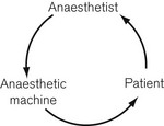
The interaction between anaesthetist, anaesthesia machine and patient may be seen as a closed-loop control system4 (Fig. 4.35): with the situation where one or more components of the control loop behave unpredictably, described as a critical incident.
Under adverse conditions the chance of injury to the patient increases with time, as shown in Fig. 4.36. There is a time delay before a problem is noticed by the anaesthetist and the cause identified. Another delay occurs before the problem is corrected, after which there should be a recovery to safe conditions if the correction is made early enough. Excessive delay in noticing the problem or in its correction may lead to permanent injury.
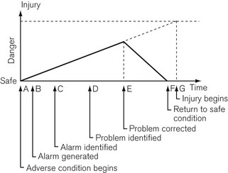
Figure 4.36 Diagram of Schreiber’s time course of a critical incident as it would occur in anaesthetic practice.
The reliability of the human for constant vigilance over long periods of time is questionable and the ability to make decisions when bombarded with multiple sensory inputs is sorely put to the test. Alarm systems should be designed to allow for as much time as possible to correct a problem before injury begins. Examination of Figure 4.36 shows that this may be accomplished by minimizing the pre-alarm period and making it clear to the anaesthetist what the problem is and its level of urgency. Research has shown that intelligent alarm systems which integrate and prioritize multiple alarm conditions can lead to a more rapid and consistent rectification of adverse incidents.5
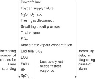
The further along the system (e.g. from the gas and electricity supplies to the patient) that a parameter is monitored (Fig. 4.37), the greater the delay before the alarm is sounded and the greater the number of possible causes of that particular problem. For example, if the oxygen supply fails, the oxygen supply alarm would sound immediately. Some seconds later, depending on the fresh gas flow into the breathing attachment, the inspired oxygen monitor alarm would become active. However, it may be more than a minute before the saturation, as indicated by a pulse oximeter, would fall below the critical level. Furthermore, the causes of a drop in SpO2 are numerous compared with the causes of the sounding of the oxygen supply pressure alarm. In this scenario, assuming multiple monitoring points of anaesthesia system and patient, an intelligent alarm system would assimilate the multiple alarm conditions and prioritize the oxygen supply failure, hence leading to the most rapid resolution of the incident.
Alarms
Much research has been done on alarms,6 alarm characteristics and those features that control the perceived urgency, namely: frequency composition, repetition rate, amplitude, and harmonic relation of the frequency components. The urgency of the alarm must be balanced against its liability to distract the target’s concentration during critical periods, and the possible nuisance effect from ‘false alarms’, as well as its effect on non-target audience (e.g. patient or surgeon). This is not an easy task; additionally, an alarm perceived as excessively intrusive may be disabled by the anaesthetist. Although the BSI and ISO publish clear standards for alarms (BS EN ISO 9703–3:1998), significant latitude is still allowed to manufacturers and even with standards compatible alarm structures it is argued that the current alarms in many popular machines are inappropriate in terms of conveying the correct urgency.7 The 9703 series of standards was withdrawn in 2004. Ideally, however, ultimately alarm signals should be identical across manufacturers for any given modality of monitoring or item of equipment. In any case, it is perhaps time manufacturers revisited this subject.
Nonetheless, the quality of modern monitoring equipment available, as well as the ease and flexibility of operator setting of alarm limits, means that the practice of disabling alarms (rather than setting alarm parameters to prevent inappropriate alarm triggering) is no longer acceptable. By the same token, alarms should not be allowed to continually sound (often a feature of inadequate implied urgency) when there is no perceived problem: this leads to habituation to the alarm sound and ultimately failure to react to appropriate alarms.
Pre-use check
It is mandatory to check the correct functioning of anaesthetic equipment before use. The Association of Anaesthetists of Great Britain and Ireland (AAGBI) publishes a ‘Checklist for Anaesthetic Equipment’ to assist in allowing a comprehensive and systematic check of equipment (Table 4.2). The most recent iteration of this, in 2004,8 recognizes the introduction of microprocessor controlled technology into anaesthetic workstations and attempts not to reduplicate the self-test cycle that modern workstations undergo on start-up. It also stresses the importance of familiarity with these potentially complex pieces of machinery and hence the need for a formal ‘induction’ onto the machine. Also noteworthy is the requirement that a log should be kept of the completion of a pre-use check according to both the requirements of the manufacturer and the AAGBI checklist.
Table 4.2 AAGBI checklist for anaesthetic equipment (with permission from AAGBI)
CHECKLIST FOR ANAESTHETIC EQUIPMENT 2004
1. Check that the anaesthetic machine is connected to the electricity supply (if appropriate) and switched on. Note: Some anaesthetic workstations may enter an integral self-test programme when switched on; those functions tested by such a programme need not be retested.
2. Check that all monitoring devices, in particular the oxygen analyzer, pulse oximeter and capnograph, are functioning and have appropriate alarm limits.
(Some monitors need to be in stand-by mode to avoid unnecessary alarms before being connected to the patient.)
3. Check with a ‘tug test’ that each pipeline is correctly inserted into the appropriate gas supply terminal. Note: Carbon dioxide cylinders should not be present on the anaesthetic machine unless requested by the anaesthetist. A blanking plug should be fitted to any empty cylinder yoke.
4. Check the operation of flowmeters (where fitted).
6. Check the breathing system to be employed.
Note: A new single-use bacterial/viral filter and angle-piece/catheter mount must be used for each patient. Packaging should not be removed until point of use.
7. Check that the ventilator is configured appropriately for its intended use.
8. Check that the anaesthetic gas scavenging system is switched on and is functioning correctly.
9. Check that all ancillary equipment which may be needed is present and working.
10. Check that an alternative means to ventilate the patient is immediately available (e.g. self-inflating bag and oxygen cylinder).
This checklist is an abbreviated version of the Association of Anaesthetists publication ‘Checking Anaesthetic Equipment 3 2004’
(endorsed by the Chief Medical Officer and the Royal College of Anaesthetists).
Specific machines
The following paragraphs are not intended as a critique or assessment of the machines. Features and failures are highlighted purely to make the reader aware of issues that may be pertinent to any device being considered. The purpose of anaesthetic machines is ultimately quite simple – the safe delivery of drugs. Increasing familiarity with a machine can therefore only reveal its inadequacies.
(Datex-Ohmeda) Aestiva/5, GE Healthcare
The Aestiva/5, and its family of machines launched in 1998, has been a very successful design of anaesthetic workstation (Fig. 4.38). It is, in all respects, a traditional pneumatic machine. There is a built-in circle system and a software-driven, pneumatically powered ventilator using the ‘enclosed bellows’ arrangement to isolate respiratory and driving gasses. The ventilator type is briefly described above and specifically in detail in Chapter 9 (Datex-Ohmeda 7900). Conventional vaporizers are mounted on the back bar. Hypoxic mixture prevention is by use of the Ohmeda Link 25 system (see Fig. 4.17). The CGO, as opposed to the integral circle breathing system, is selected by a lever discretely positioned to the side of the absorber.
Its popularity owes more to good ergonomic design than the use of advanced technology. Without doubt, much of this is due to the long-established Datex-Ohmeda AS/3 design of patient monitor. This monitor has hot swappable individual modules for an extensive number of parameters and benefits from a flexible and well laid out display and intuitive operating menu structure. This monitor is neatly housed within the Aestiva with a remote flat panel display which can be mounted on the swing arm of the machine to sit above or below the control panel of the ventilator. Depending on the configuration requested, the machine can offer a significant amount of flat storage or working surfaces and drawers. Use of a single, foot-operated brake lever renders the machine freely mobile, allowing easy positioning of machine for access to the patient in any operating room set-up. The overall appearance of the machine is unfussy with clearly defined instrument clusters.
(Datex-Ohmeda) ADU, GE Healthcare
First released in 1995 (‘ADU 95’) and with a subsequent ‘ADU 98’, this is still a striking-looking machine by virtue of the absence of traditional rotameters and vaporizers and the presence of twin flat panel displays for patient monitoring and control and monitoring of the pneumatic systems (Fig. 4.39). GE Healthcare (who took over Datex-Ohmeda) ceased production of this device in February 2010 with over 11 000 units having been put into service worldwide.
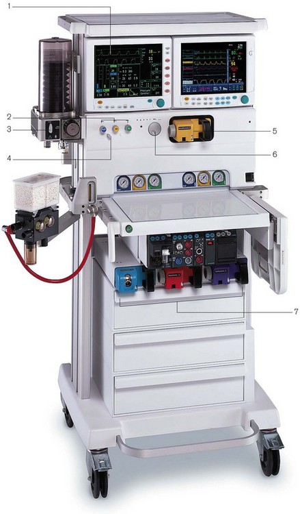
Figure 4.39 The Datex-Ohmeda ADU. Shown here with US standard colour coding for gasses. (1) Ventilator user interface. (2) Gas flow needle valve controls. (3) Ventilator selection switch. (4) Side gas selection switch. (5) Aladin cassette. (6) Agent concentration selection. (7) Vaporizer storage rack.
Photograph courtesy of Datex-Ohmeda.
The ADU is essentially a modular system and comprises:
• a wall gas unit, taking gas inlets from pipeline supplies and reserve cylinders
• a fresh gas control unit responsible also for volatile agent admixture
• an electronic ventilator unit
• a central electronic unit for integrating control and monitoring
• an attached bellows block and compact circle absorber system.
The ventilator and fresh gas control units have their own microprocessor controls which communicate through the central electronic unit. A number of features of the ADU stand out for individual consideration (Fig. 4.40).
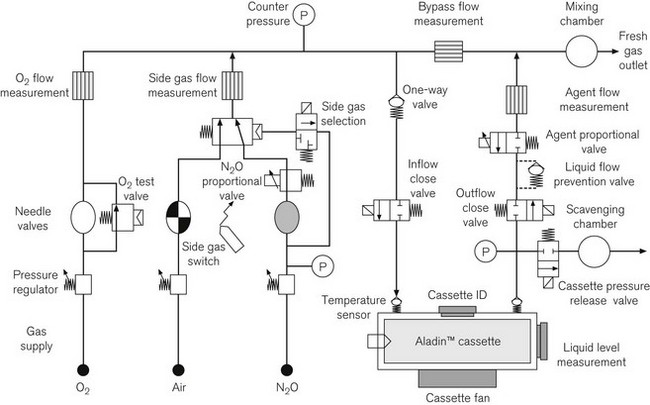
At the time of its inception it was unique in its electronic control of agent concentration. The Aladin cassette system none the less relies on the conventional approach of saturation of a proportion of the fresh gas flow by passage through a vaporizing chamber. Here though, when the desired agent concentration is selected on the machine, a proportional valve controls the flow of gas through the vaporizer. By comparing the bypass flow measurement within the machine with the vaporizer flow measurement, the proportional valve is set to achieve the desired target (Fig. 4.40). The system is described in greater detail in Chapter 3. Note that in the ADU feedback control of the agent concentration relies on calculations of flow and does not involve measurement of agent concentration.
Dräger Primus
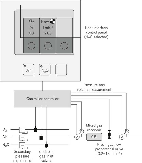
The Dräger Primus, available since 2003 (Fig. 4.41), represented another departure in design. Its main distinguishing feature is the electronic fresh gas mixer.
Here, fresh gas is mixed entirely by electronically controlled valves according to the desired total flow and oxygen concentration. The ADU, for comparison, utilizes mechanical needle valves set by the operator with subsequent electronic adjustment to the flow of N2O. In the Primus the operator selects air or N2O as the carrier gas, and sets a total flow and the desired oxygen concentration (Fig. 4.42). A gas controller unit under feedback control sequentially opens high-speed solenoid valves to allow oxygen and the secondary gas to fill the mixed gas reservoir at the desired concentration. A proportional valve distal to this controls total flow into the pneumatic system. With this form of microprocessor control it is possible to have preset defaults for minimum oxygen concentration and this may be linked to the total set gas flow such that at total flows below 1 l min–1 the machine will maintain a minimum oxygen flow of 250 ml min–1. Gas flows are shown as virtual flowmeters on the control panel.
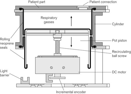
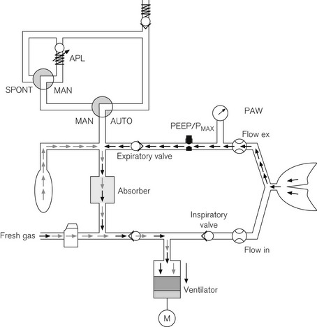
The Primus, in common with some other machines in the Dräger range, uses an electrically driven piston ventilator (Fig. 4.43) capable of generating flows up to 180 l min–1 with a tidal volume up to 1400 ml. The ventilator itself is further discussed in Chapter 9. By arranging fresh gas inflow into the circle on the expiratory side of the ventilator circuit (before the ventilator) and separating them using a non-return valve, the system achieves fresh flow gas decoupling of the delivered tidal volume. An incremental encoder comprising a perforated disk attached to the drive spindle of the piston gives precise measurement of piston displacement. Measurement of the expired gas flow from the patient allows close matching of the piston’s downstroke so as not to generate negative end expiratory pressure whilst also not entraining gas from outside the circuit. This is necessary for the preservation of low fresh gas flows. Gas flow measurement in the patient circuit uses hot wire anemometry. The reservoir bag is in circuit and functional during mechanical ventilation, taking up excess gas flows and also providing a buffer during the downstroke of the piston ventilator (Fig. 4.44). The expiratory control valve uses a proportional valve as discussed above (Fig. 4.29). The software driven ‘E Ventilator’ is also able to ventilate in pressure control and assisted spontaneous breathing modes.
Dräger Zeus
The Zeus, launched initially in 2003 and in the UK in 2005, represents Dräger’s most advanced anaesthesia workstation to date and employs a number of novel approaches in its electronic control of gas delivery and ventilation that mark it out from other machines currently available. The package as a whole consequently has few of the visual aspects that would normally identify an anaesthetic machine (Fig. 4.45). Ergonomics is addressed by a central brake pedal, 180° rotating capability of the display panel arm and push through drawers allowing the machine to be used from either side. The outstanding features of the device are its automated control of patient gas composition using a choice of two different control algorithms and its use of a novel miniature turbine within the breathing system to power patient gas circulation and ventilation. The Zeus includes the following components:
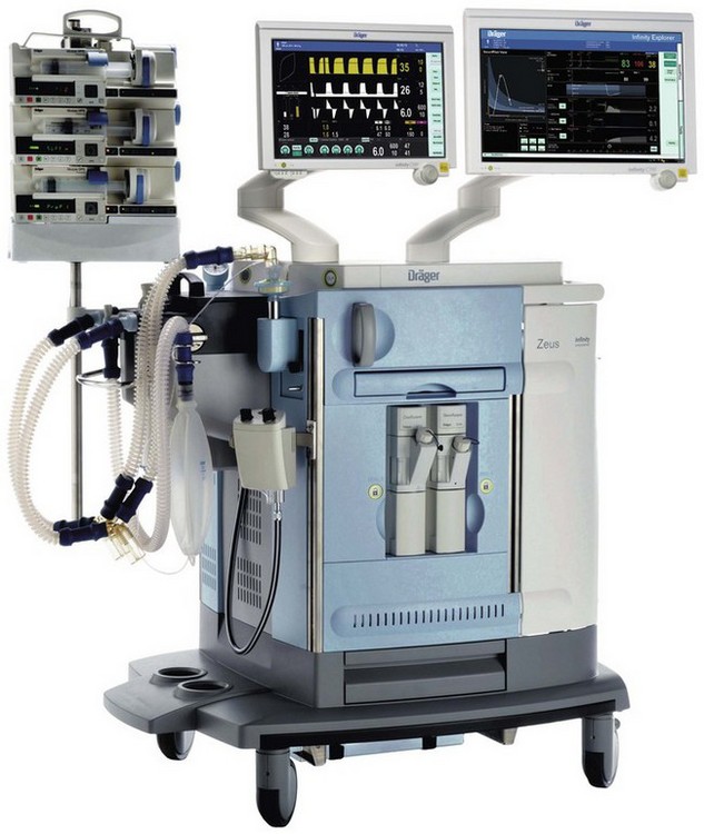
Figure 4.45 Dräger Zeus anaesthesia workstation with optional syringe pumps for intravenous anaesthesia that may be controlled through the workstation and a monitor screen showing a decision support system (Chapter 22).
Photograph courtesy of Dräger Medical AG & Co, Lubeck, Germany.
• Windows NT computer with system display unit for operation of therapy control and monitoring
• Electronic gas and anaesthetic agent flow control with closed-loop feedback control system
• Electronically controlled and driven blower with circle breathing system
• Optional syringe pumps for intravenous anaesthesia (currently, however, TCI is not available on these pumps).
Gasses are delivered to a digital gas mixer from secondary regulators at 2.4 bar. Gas mixing for the fresh gas flow into the patient circuit is then achieved by two banks of five digital switching valves (solenoids): one bank for control of oxygen and the other used for either air or nitrous oxide. Volatile admixture is from the DIVA unit (Direct Injection of Volatile Agent, described in detail in Chapter 3). This is an air-pressurized, electronically controlled, heated, measured flow vaporizer. This preceding arrangement for control of the gas mixture, along with two parallel in-built gas analysis modules, allows software-driven automated control of inspired oxygen and end tidal volatile agent concentration as well as the fresh gas flow (FGF) rates in the appropriate control modes. The user, for example, sets the desired end tidal concentration of volatile agent; the agent concentration in the FGF into the circle system is then controlled by the machine to achieve and maintain that target concentration in expired patient gas. Labelled by the manufacturer as ‘Target Controlled Anaesthesia’, it allows something akin to the ‘effect site Target Controlled Infusion’ of intravenous drugs for volatile agents. In ‘auto control’ mode different algorithms can be made to operate to provide both rapid adjustment of gas composition and economical use of volatile agents in the ‘uptake mode’ where oxygen concentration is only adjusted down by patient uptake rather than new gas delivery. There is not room here to elucidate in any detail the specifics of these automatic modes.
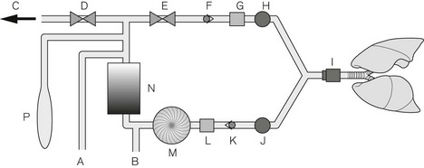
A small turbine (Fig. 4.46) generates the pressure required for ventilation and to improve the mixing of gasses in the patient circuit it also provides a circulatory flow during spontaneous respiration. In operation the peak inspiratory pressure that can be generated is about 50 cm H2O. Fig. 4.47 shows how this, in combination with a proportional valve that closes fully or partially and the hot wire anemometry flow sensors placed in the patient circuit, can effect all modes of ventilation and PEEP.
GE Healthcare, Aisys
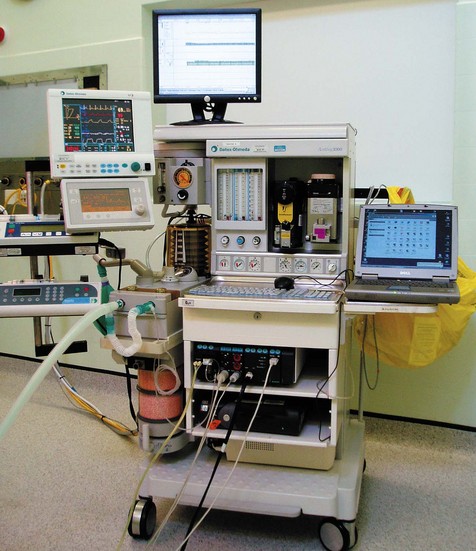
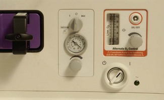
The Aisys (coined form Anaesthesia Integrated System) launched in the UK in 2006 is this manufacturer’s fully electronically controlled anaesthetic workstation (Fig. 4.1). In contrast to the Datex-Ohmeda ADU (see above), this model uses electronic control of gas flow into the patient circuit, doing away with the needle valves seen in the ADU. It is in all other respects a fairly conventional design. The vaporizer module uses identical technology to the ADU and the ventilator assembly is the conventional proportional valve driven enclosed bellows system of the Datex-Ohmeda 7900 series. Unlike the externally connected breathing system of the ADU, however, the circle breathing system here is very much integral to the machine. Gas flow into this circle system is such that for use with other breathing systems (e.g. Mapleson A or D), by selecting a non-circle mode on the machine control panel the inspiratory outlet of the ‘circle’ may be used as a common gas outlet (CGO). The machine may also be optioned with a switchable separate CGO as in the Aestiva.
Fig. 4.48 shows the pneumatic system of the Aisys. The emergency oxygen flush button and the auxiliary O2 flowmeter are direct mechanical systems and do not require the machine to be powered on. The alternate O2 flowmeter is in series with the master on/off switch and is provided as a parallel back-up system in case of failure of the display unit or electronic control of the gas mixer when the workstation is switched on and functional (Fig. 4.49). Under such circumstances it should deploy automatically and allow the manual control of oxygen into the patient circuit. Depending on the source of the problem, it is possible that electronic control of gas flow to the vaporizer is maintained and hence volatile agents can still be administered, though of course there would be no second or carrier gas.
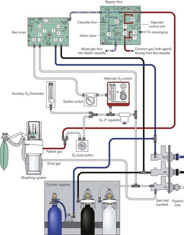
Figure 4.48 Simplified pneumatic system and associated control modules of the Aisys. S, selector valve (solenoid); F, flow control (proportional valve); T, pressure transducer; H, hot wire anemometer (flow meter); DT, differential pressure transducer. The reserve N2O cylinder is housed separately on the machine and is attached via flexible high pressure tubing to its regulator.
Redrawn with permission of GE Healthcare.
1 Alexander JP, Watters CH, Dodds WJ, McNeill WE. The Engström Elsa anaesthetic machine. An electronic system for anaesthesia. Anaesthesia. 1990;45:746–750.
2 Medicines and Healthcare products Regulatory Agency. Medical Device Alert, Ref: MDA/2010/052. Anaesthetic vaporizers used to administer volatile agents for the maintenance of anaesthesia – all manufacturers. Department of Health 2010, UK. http://www.mhra.gov.uk/Publications/Safetywarnings/MedicalDeviceAlerts/CON085024.
3 Chawla AV, Newton NI. Machine and monitoring failure from electrical overloading. Anaesthesia. 2002;57:1134–1135.
4 Schreiber PJ, Schreiber J. Structured alarm systems for the operating room. J Clin Monit. 1989;5:201–204.
5 Westenskow DR, Orr JA, Simon FH, et al. Intelligent alarms reduce anaesthesiologist’s response time to critical faults. Anaesthesiology. 1992;77:1074–1079.
6 . Auditory Alarms in Critical Care Settings: Alarm Bibliography, University of Maryland, Baltimore http://hfrp.umm.edu/alarms/Alarms_bibliography.htm
7 Mondor TA, Finley GA. The perceived urgency of auditory warning alarms used in the hospital operating room is inappropriate. Can J Anaesth. 2003;50:221–228.
8 . Checking Anaesthetic Equipment 3, The Association of Anaesthetists of Great Britain and Ireland, London 2004 http://www.aagbi.org/guidelines.html
[/level-membership-for-anesthesiology-category][not-level-membership-for-anesthesiology-category]
Chapter 4 The anaesthetic workstation
The anaesthetic workstation (Fig. 4.1) has evolved over the years from the simple inhaler for the admixture of volatile anaesthetics, through anaesthetic machines with calibrated delivery of inspired agents to the current modern workstation complete with integral ventilator, breathing system and patient and machine monitoring. Automated record keeping systems allow integration of the machine into institutional information networks and, more recently, online access to expert systems for decision support (see Chapter 22, Information Technology and the Anaesthetic Workstation). Such systems remain rare and in spite of the diminishing costs and expanding capabilities of electronic-microprocessor-based control systems, simple pneumatic anaesthetic machines with needle-valve flowmeters and conventional vaporizers still dominate in UK hospitals. There has been no ‘revolution’ in anaesthetic machines as yet.
Products offered to a market place by successful companies reflect a balance of technology, economics and what the end user is or will be willing to engage with. In this respect the particular machines described in the latter section of this chapter when viewed as a whole, demonstrate how anaesthetists have only gradually come to be prepared to use ‘fly by wire’ technology: electronically controlled machines operated through a computer interface. Even within anaesthesia such technology is not new; along the way machines with iterations of such technology such as the Engstrom Elsa1 have perished in the market where the devices really were ‘before their time’.
When the anaesthetic machine appears a physically, if not intellectually, impenetrable box with opaque control systems operated through a simple video screen, it is tempting to think that the study of joints in metal tubing, pressure regulators, mechanical hypoxia prevention systems and flow valves is somewhat anachronistic. It may be, but caution is advised: the user manual for a state of the art workstation such as the Dräger Zeus runs to 346 pages (it is difficult to envisage more than a singular instruction sheet for the original Boyle’s trolley) and reflects the complexity of the processes underlying these devices. The logic and control of such systems is an elaboration of what has gone before and an understanding of the processes is necessary if we are to be able to cope with the machines and to demand better performance or deal with fault conditions. Additionally it seems we are occasionally required to relearn lessons of the past.2
Throughout the changes above, developments have been driven by the need for safety addressed by the inclusion of fail-safe systems, and by ‘the designing out’ of the possibilities of dangerous user errors. This aspect of the workstation may be regarded as having developed through successive generations of improvements and modifications having been incorporated, such that the ‘anaesthetic machine’ component of a modern workstation is still usually recognizable as a descendant of the first-generation Boyle’s trolley. Over time, technological safety features have become enshrined in national and international standards which are largely adhered to. As such, an analysis of critical incidents may help to inform a logical approach to the understanding of the safety features and design of modern machines, and for this reason such a section is included in this chapter.
One notable change over the last few years has been the narrowing gap between anaesthesia ventilators and intensive care ventilators. Software-driven, electronically controlled devices are seen that, if not identical in technology to the ITU types, are at least capable of emulating most ventilatory modes if desired. Simple purely mechanical ventilators are seen now only in devices purpose built for the developing countries (see Chapter 27). The reader is referred to Chapters 9 and 10 for more detailed information on ventilators.
Functions of the modern workstation
• Safe provision, selection and delivery of anaesthetic gasses and vapours together with an appropriate built-in breathing system, usually a circle system
• Provision of back-up supplies of gasses in the event of failure of the primary sources
• Respiratory support in the form of sophisticated automatic ventilators capable of managing the full range of patient needs
• Monitoring of machine function and settings
• Monitoring of patient physiological variables
• Automated archived record keeping (or at least the facility to output monitored parameters to other systems) and ideally on-line access to information and administration networks
• The integration of the display and auditory signalling of monitored modalities
• Provision of appropriate connection to an anaesthetic gas scavenging system
• Provision of medical vacuum via a suction regulator
• Provision of supplemental oxygen using an auxiliary O2 flowmeter (for reduced risk of inadvertent anaesthesia)
• Work surface and storage facility for ‘everyday’ items
• Provision of mains electricity sockets for low-consumption items used in association with delivery or monitoring of anaesthesia, e.g. syringe pumps. (international standards preclude the powering of one medical device from another. For the purpose of this standard, the workstation is seen as a resuscitation trolley.)
Development of the anaesthetic workstation
Integrated and modular designs
• a circle breathing system and usually a ‘bag in bottle’ arrangement to separate respiratory gasses from the usually pneumatically driven ventilator (see Dräger Zeus for an alternative configuration)
• a choice of ventilator, often a single design but software driven and available in a variety of software configurations
• usually one of a choice of back bar vaporizer attachment systems, i.e. Selectatec or Dräger, allowing vaporizers to be exchanged for a choice of volatile agent; however, some newer electronically controlled machines utilize their own proprietary systems for volatile agent dosing (see later)
• a patient monitor of choice, itself often of a modular design where individual parameters can be ‘hot swapped’, i.e. exchanged whilst actually in use
• an archived/networked or stand alone anaesthesia record system if so desired
Electronics: monitoring or control?
The flow of gasses through the workstation has largely remained under pneumatic and direct mechanical control. There are currently only very few machines offering electronic servo control of gas flow and/or vapour concentrations. Although needle valves (see below) remain ubiquitous for control of gas flows, many machines do use electronic monitoring (and display) of the flow rates instead of rotameters (see Chapter 2).
The anaesthetic delivery system
A typical machine consists of:
• a rigid metal framework on wheels; attached to this is a source of compressed gas consisting of a pipeline system and/or metal cylinders containing the relevant gasses
• pressure regulators for reducing the high pressures in the attached cylinders to machine working pressures of approximately 420 kPa (60 psi) or 310 kPa (45 psi) in some countries. (The British Standard stipulates 420 kPa which is 61.3 psi. For convenience this has been rounded off to 60 psi)
• secondary regulators for damping surges in machine working pressure (see below)
• pressure gauges to show pipeline and cylinder pressures
• a method of metering (e.g. flowmeters), using adjustable valves for proportioning and mixing the various gasses
• a system for attaching vaporizers to the anaesthetic machine for the addition of volatile anaesthetic agents to the gas mixture
• a safety mechanism to warn of the failure of the oxygen supply and to prevent hypoxic mixtures of gas/vapour reaching the patient (oxygen failure warning device)
• a safety mechanism for releasing high-pressure build-up of gasses (back bar pressure relief valve) should a fault occur in the machine
• a system that bypasses the flowmeter for the administration of a high flow of pure oxygen in an emergency
• in-built connection to a circle breathing system with the facility to switch to a single outlet for delivering the gasses and vapours to any other breathing system (the common gas outlet).
The compressed gas attachments
Cylinders
The cylinders are clamped onto the machine by a yoke arrangement and secured tightly using a wing-nut (Fig. 4.2). To prevent installation of the wrong gas cylinder to a yoke, the cylinder heads are coded with appropriately positioned holes that match pins on the machine yoke. This is called a pin index system, for which there is an internationally agreed standard (ISO 407:2004) (see Fig. 1.5). A thin neoprene and aluminium washer (Bodok seal) is interposed between the cylinder head and yoke to provide a gas-tight seal when the two are clamped together.
A leak of not more than 15 ml min–1 through an open yoke is acceptable in new machines. However, in older machines the non-return valve may not be as efficient owing either to the design (the valve not being spring loaded) or to wear and tear, and could result in greater than acceptable backpressure leaks. These leaks, when occurring unexpectedly, have been shown to alter the composition of the gas leaving the flowmeter block and have resulted in the delivery of a hypoxic gas mixture to an attached breathing system (see section on Flowmeters). Blanking plugs (dummy cylinder heads) are available and should be inserted into all empty yokes to overcome this problem (Fig. 4.3).
Pipelines
Each pipeline source is attached to the machine via a gas-specific connection. In the UK this is called a NIST (non-interchangeable screw-threaded) connection and is discussed in greater detail in Chapter 1 (see Fig. 1.29). In the USA, a similar system is employed called DISS (Diameter Indexed Safety System). However, the diameters of the nipples and bodies for the various connections are smaller and not compatible with the NIST system.
Pressure (contents) gauges
The pressure in cylinders and pipelines is measured by Bourdon-type gauges (see Fig. 2.6). The gas entry to the pressure gauge has a constriction so as to smooth out surges in pressure that could damage the gauge, as well as to prevent total and rapid loss of gas should a gauge rupture. The gauges are labelled and colour coded for each gas, according to the standards for each country. They are also calibrated for each gas used on the machine. The scale on the gauge extends to a pressure at least 33% greater than either the filling pressure of the cylinder or pipeline pressure (at a temperature of 20°C). Each cylinder yoke may be fitted with a gauge or, alternatively, a single-cast brass block may be used to house the NIST/DISS pipeline connection, cylinder yoke, pressure regulator and housings for the pressure gauges (Fig 4.4). This minimizes the number of connections and potential leaks, but is a somewhat dated arrangement now.
Single-block manifold
The single-cast brass block has given way in recent years to the single-block gas manifold (Fig. 4.5), which is drilled to accommodate as many as possible of the gas pipeline and pneumatic valve interconnections. The small, compact manifold (Fig. 4.5A), for reasons of design economy, does not carry the cylinder yokes and is hence typically downstream of the primary pressure regulator which is invariably part of the cylinder yoke assembly (Fig. 4.5B).
Pressure regulators (reducing valves)
Pressure regulators are used on anaesthetic machines for three main reasons:
1. The pressure delivered from a cylinder is far too high to be used with safety in apparatus where a sudden surge of pressure might accidentally be delivered to the patient.
2. If the pressure were not reduced, flow-control (fine-adjustment) valves, tubing and various other parts of the apparatus would have to be much more robust, and a fine and accurate control of gas flow would be difficult to achieve. There would also be a danger of pressure building up and damaging other components of the apparatus.
3. As the contents of a cylinder are exhausted, the pressure within the cylinder falls. If there were no regulating mechanism to maintain a constant reduced pressure, continual adjustment would have to be made of the flow-control valve in order to maintain a given flow rate.
Working principles
In Fig. 4.6, the chamber C is enclosed on one side by the diaphragm D. As gas enters the chamber through the valve V, the pressure in the chamber is increased and the diaphragm is distended against its own elastic recoil and the force from the spring S. Eventually the pressure rises high enough to move the diaphragm far enough to close valve V. The pressure at which this occurs may be varied by adjusting the screw X so as to alter the force exerted by the spring S. If gas is allowed to escape from the outlet of the chamber, the pressure falls and valve V reopens. When the regulator is in use, a steady pressure is maintained in the chamber by the partial opening of valve V.
In another form of regulator (Adams valve), the push-rod is replaced by a ‘lazy tongs’ toggle arrangement (Fig. 4.7), which reverses the direction of the thrust transmitted from the diaphragm.
The accuracy of regulators
Let us consider that the push-rod is pushed downward by two forces: the compression in the spring and the elastic recoil of the diaphragm (Fig. 4.8). Let these be added together and represented by S. The force that opposes S consists of two parts: the high pressure (P) of the gas pushing on the valve V over an area of a; and the low pressure (p) acting on the diaphragm over an area A, so:
In the Adams valve (Fig. 4.9), it can be seen that the pressure P exerted by the high-pressure gas to open valve V is assisted by the spring and the recoil of the diaphragm S. These forces jointly oppose the force exerted by the low-pressure gas on the diaphragm, so:
Now as P falls, so does p; therefore the regulated pressure falls slightly as the cylinder pressure drops. At the same time the valve V opens slightly and this, by allowing the spring to expand, reduces S, which slightly accentuates the fall in p. The fall of p can be minimized by making S great compared with Pa.
There are several types of pressure regulator available, the choice being dependent on:
Interchangeability of regulators
Pressure regulators used to be labelled and coded for specific gasses. This is because a special alloy was required in the valve seating for some gasses (e.g. nitrous oxide) in order to prevent corrosion. However, modern regulators are designed to be compatible with all anaesthetic gasses. This is achieved by using materials such as PTFE coatings on the diaphragms together with nitrile (a hard synthetic rubber) valve seats and chrome-plated brass for the regulator body (Fig. 4.10). These too are described as ‘universal’ by their manufacturers.
Common faults in regulators
• Damage to the soft seating of valves may occur as a result of the presence of grit or dust, usually from a dirty cylinder. This may cause a steady build-up of pressure in the apparatus when the cylinder is left turned on but with no gas flowing.
• A hissing noise may indicate a leaking or burst diaphragm. The regulator will need replacing or repairing by the manufacturer or service engineer.
• Adams valves sometimes develop a fault that causes continual ‘jumping’ of the flowmeter bobbin, indicating an intermittent change of pressure and flow rate. This is usually due to the ‘lazy tongs’ sticking as a result of wear, but it may also be caused by small particles of grit or metal in the lazy tongs or the valve seating.
Relief valves on regulators
Safety blow-off valves are often fitted on the downstream side of regulators to allow the escape of gas if, by accident, the regulators fail and allow a high-output pressure. With a regulator designed to give a pressure of 420 kPa (60 psi), the relief valve may be set at 525 kPa (70 psi). These valves may be spring loaded (Fig. 4.10), in which case they close when the pressure falls again, or they may operate by rupture, in which case they remain open until repaired. As a further safety feature, a flow restrictor (usually in the form of a simple pin hole orifice) on the high pressure inlet side of the regulator, limits maximal flow from the cylinder to between 70 and 150 l min–1, ensuring that in the event of regulator failure the high-pressure relief valve can dump the maximal flow without further pressure rises.
Secondary pressure regulators
Several factors cause the machine working pressure (420 kPa in the UK) to fluctuate by up to 20%. For example, at times of peak demand in a hospital, pipeline pressures may well drop by this amount. Similarly, if an auxiliary outlet on the anaesthetic machine is used to drive a ventilator with a very high sudden and intermittent gas demand, a similar pressure drop will occur before the pipeline or cylinder is able to restore the supply. These pressure fluctuations produce parallel fluctuations in flowmeter performance. A second (secondary) regulator set below the anticipated pressure drop smoothes out the supply, minimizing these fluctuations. This is important in machines incorporating mechanically linked anti-hypoxia systems attached to the flowmeter bank (see below), as these systems assume that the oxygen supply pressure is constant in order to achieve an accurate flow of gas. A mechanically linked system would not be able to detect altered gas flow rates caused by changing pressures. Furthermore, secondary regulators also prolong the accurate supply of oxygen to the flowmeter if there is a gradual failure of the oxygen supply (i.e. cylinder emptying) prior to the oxygen failure warning device being activated.
Flow restrictors
It was an occasional practice to entirely omit regulators from the pipeline supply (420 kPa (60 psi)) in older anaesthetic machines. Sudden pressure surges at the patient end of the anaesthetic machine were prevented by flow restrictors. These consisted of constrictions in the regulated pressure pipework upstream of the flowmeters. The disadvantage of using flow restrictors without regulators was that changes in pipeline pressure were reflected in changes of flow rate, which made readjustment of the flow control valves necessary. Also, there was a danger that if there was an obstruction at the outlet from the anaesthetic machine, pressure could build up in the vaporizers and cause damage. This was normally prevented by the inclusion of a ‘blow-off’ safety valve (see section on ‘the back bar’ below). Flow restrictors do not normally require any maintenance.
Gas-tight connections within the machine
Whilst there is no standard for the design of gas piping within the machine, with the advent of nylon tubing, manufacturers tend to use pipes of differing diameters and/or sometimes colour for the different gasses to reduce the risk of accidental misconnection during servicing and assembly (see Fig 4.5A where the white tubing is for oxygen and the blue and black, respectively, for nitrous oxide and air).
Joints in metal tubing
1. One pipe may have a slightly larger diameter than the other so that they overlap (Fig. 4.11A).
2. Where the diameters are similar, both ends are inserted into a sleeve of metal (Fig. 4.11B).
The adjacent surfaces are then bonded together by brazing (applying a molten filler alloy whose melting temperature is above 430°C) or hard soldering (a similar principle using an alloy with a lower melting point). After making such a joint it is important that all traces of flux are removed. Flux is a material applied to the surfaces to be bonded, allowing the molten filler to spread more evenly. More recently, a system of brazing copper pipes and brass fittings without flux has been evolved. This is used particularly for medical gas pipeline installations.
Where provision has to be made for disconnection and reconnection of a joint, a union is used. This consists of two parts held together in a gas-tight manner, usually by a nut or cap, which screws onto a parallel male thread. Figure 4.11C shows a ball and cone (or cone seated) union, in which the seating is by direct metal-to-metal contact. A flange (or flat seated) union (Fig. 4.11D) requires a washer to complete the seal. With pipes carrying oxygen, this washer should be of non-flammable material.
For some other purposes tapered threads (Fig. 4.11E) may be used and the seal made either by screwing them down extremely tightly or by interposing a sealing compound such as PTFE (polytetrafluoroethylene/Teflon) in the form of a tape. The joint between the valve block and the body of a medical gas cylinder, for example, is sealed by a metal foil between two tapered threads and is designed to melt at high temperatures, allowing gradual release of cylinder contents.
Other detachable joints
High-density nylon tubing, connected by metal junctions, is now ubiquitous in anaesthetic machines (Fig. 4.12). It is cheaper, less prone to rupture and simpler to install. Joints are made gas-tight by an ‘O’-ring fitted between the components. This consists of a simple ring made to a fine tolerance out of a material such as neoprene. It is housed in a recess in the larger component to stop it becoming dislodged.
Valve glands
Where a valve spindle passes from an area of high pressure to one of low pressure, provision must be made to prevent the leak of gasses along the line of the spindle. This is achieved by means of a gland. In Figure 4.13, the nut ‘N’ must be screwed down sufficiently tightly to ensure that the packing is applied so closely to the spindle that no gas can escape by this route. There is provision for the nut to be tightened down further to prevent leaks as the packing wears.
The principle can be used for a high-pressure gland, such as that of an oxygen cylinder (see Chapter 1), or in a low-pressure gland such as that in a flowmeter (Fig. 4.14). In the case of high-pressure valves, a special type of leather or long-fibre asbestos was at one time used for the packing, but modern glands are filled with specially shaped nylon. Those in low-pressure flow control valves may be filled with rubber, nylon, neoprene or cotton.
[/not-level-membership-for-anesthesiology-category]
