Chapter 5 Breathing systems and their components
Definitions
• Breathing systems. In this chapter the term breathing system may be used to describe both the apparatus and the mode of operation by which medical gasses and inhalational agents are delivered to the patient, i.e. a ‘Mapleson D type breathing system’ (mode of operation) would describe the mode of operation of a ‘Bain breathing system’ (apparatus). The term breathing circuit seems to have reappeared also in this context in current anaesthetic literature. However, strictly speaking, a circuit refers to apparatus that allows recirculation of medical gasses and vapours and does not accurately describe other pieces of apparatus used for medical gas delivery
• Rebreathing. Rebreathing in anaesthetic systems now conventionally refers to the rebreathing of some or all of the previously exhaled gasses, including carbon dioxide and water vapour. (Rebreathing apparatus in other spheres, e.g. fire fighting and underwater diving, has always referred to the recirculation of expired gas suitably purified and with the oxygen content restored or increased.)
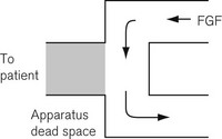
• Apparatus dead space. This refers to that volume within the apparatus that may contain exhaled patient gas and which will be rebreathed at the beginning of a subsequent inspiratory breath (Fig. 5.1).
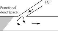
• Functional dead space. Some systems may well have a smaller ‘functional’ dead space owing to the flushing effect of a continuous fresh gas stream at the end of expiration replacing exhaled gas in the apparatus dead space (Fig. 5.2).
Classification of breathing systems
These may be classified according to function:
• non-rebreathing systems (utilizing non-rebreathing valves)
• systems where some rebreathing of previously exhaled gas is possible, but normally prevented by the flow of fresh gas through the system
• non-rebreathing systems utilizing carbon dioxide absorption and recirculation of gasses:


Non-rebreathing systems
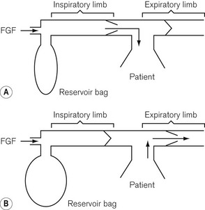
Fresh gas enters the system via an inspiratory limb (Fig 5.3A). This is a length of hosing that has a sufficiently wide bore to minimize any resistance to airflow. It is reinforced so as to prevent collapse from sub-atmospheric pressure either by manufacturing it with corrugations or by bonding a reinforcing spiral onto the outside of the hose. Both of these methods also allow the tube to bend without kinking. The fresh gas entering is either sucked in by the patient’s inspiratory effort or blown in during controlled ventilation and enters the non-rebreathing valve. This valve is so constructed that when it opens to admit inspiratory gas, it occludes the expiratory limb of the system (see Fig. 5.3A). When the patient exhales, the reverse occurs, i.e. the valve mechanism moves to occlude the inspiratory limb and opens the expiratory limb to allow expired gasses to escape (Fig. 5.3B).
Systems where rebreathing is possible
Mapleson’s classification of breathing systems
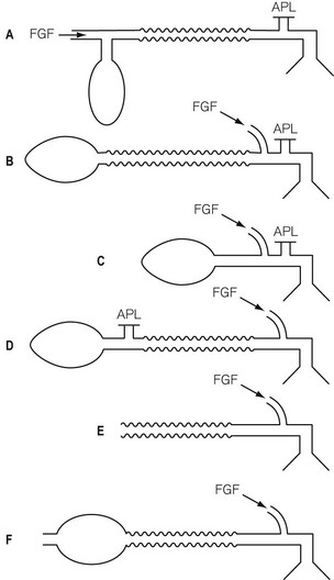
Fig. 5.4 illustrates a modified Mapleson classification of breathing systems. These all contain similar components but are assembled in different sequences in order to be used more conveniently in specific circumstances. However, as a result, the efficiency of each system is different. They are catalogued in order (A, B, C, D, E, F) of increased requirement of fresh gas flow to prevent rebreathing during spontaneous respiration. System A requires. 0.8–1 times the patient’s minute ventilation, B and C require 1.5–2 times the patient’s minute ventilation and systems D, E and F (all functionally similar) require 2–3 times the patient’s minute ventilation to prevent rebreathing during spontaneous respiration.
Working principles of breathing systems
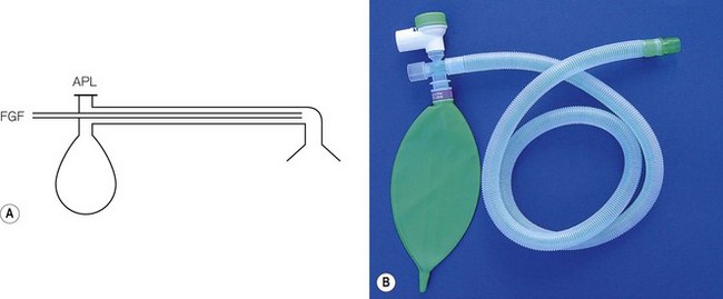
Mapleson A breathing system
The Mapleson A system illustrated in figure 5.5 is the ‘Magill attachment’ as popularized by Sir Ivan Magill in the 1920s. It consists of the following:
• At one end, an inlet for fresh gas linked to a 2 litre distensible rubber or neoprene reservoir bag. (Not rebreathing bag, as the patient’s exhaled gasses should never be allowed to pass back into it.) This is attached to:
• a length of corrugated breathing hose (minimum length 110 cm with an internal volume of 550 ml). This represents slightly more than the average tidal volume in an anaesthetized adult breathing spontaneously. This volume is important as it minimizes the backtracking of exhaled alveolar gas back to the reservoir bag (see below). This is in turn connected to:
• a variable tension, spring-loaded flap valve for venting of exhaled gasses. This valve should be attached at the opposite end of the system from the reservoir bag and as close to the patient as possible. It will be subsequently referred to as an APL (adjustable pressure limiting) valve.
• The first inspiration. In Fig. 5.5A the reservoir bag and breathing hose have been filled by an ideal fresh gas flow and attached (with a gas-tight fit) to the patient, who is about to take a breath. The whole system is therefore full of fresh gas. As the patient inspires, the gasses are drawn into the lungs at a rate greater than the fresh gas flow and so the reservoir bag partially empties as shown in Fig. 5.5B.
• Expiration. In Fig. 5.5C the patient has begun to exhale, and because the reservoir bag is not full, the exhaled gasses are breathed back along the corrugated hose, pushing the fresh gasses in the hose back towards the reservoir bag. However, before the exhaled gasses can pass as far as the reservoir bag (hence the importance of the length of the inspiratory hose), the latter has been refilled by the fresh gasses from the corrugated hose plus the continuing fresh gas flow from the anaesthetic machine.
• End-expiratory pause. The next stage is the end-expiratory pause. The fresh gas flow entering the system now drives the exhaled gasses, or some that had tracked back along the corrugated hose, out through the APL valve. It can be seen that the expiratory pause is important because it prevents the potential for the rebreathing of exhaled alveolar gasses that would otherwise be contained in the hose at the end of expiration (Fig. 5.5D).
• there is mixing of the various gaseous interfaces, which reduces the theoretical efficiency of the system
• occasionally, larger than expected tidal volumes may well be exhaled and, therefore, reach the reservoir bag, in which case carbon dioxide will contaminate the reservoir bag and the subsequent inspiratory gasses
• rapid respiratory rates will reduce or even eliminate an end-expiratory pause and reduce the potential for carbon dioxide elimination that this pause allows.
Mapleson A system and controlled ventilation
The mechanical aspects of the Mapleson A (Fig. 5.6) system (Magill attachment) as described above relate to its use in spontaneous respiration. However, if controlled or assisted ventilation is used, with the patient’s lungs inflated by means of squeezing the reservoir bag, a different state of affairs occurs. With the same fresh gas flows as before, we would see the following:
• Inspiratory phase. The APL valve has to be kept almost closed so that sufficient pressure can develop in the system to inflate the lungs. During the first inspiratory phase with the anaesthetist squeezing the bag, some of the fresh gasses are blown out of the valve.
• Expiratory phase. At the end of inspiration, the reservoir bag may be almost empty, and as soon as the anaesthetist relaxes his pressure on it, the patient exhales into the corrugated hose. The exhaled dead space and alveolar gasses pass further back along the breathing hose and may even enter the reservoir bag. The bag rarely fills completely and so there is usually insufficient pressure within the system to open the APL valve during this phase.
When the anaesthetist squeezes the bag again, the first gasses to enter the patient’s lungs will be the previously exhaled alveolar gasses. The volume of gasses escaping via the APL valve during this second inspiratory phase is initially small (the valve being almost closed), but gradually increases as the pressure in the system rises towards the maximum inspiration. Therefore, the greatest amount of gas will he dumped late in the cycle and will consist mainly of fresh gas. Under these circumstances there is considerable rebreathing (Fig. 5.6 see shading). Furthermore, as alveolar gas will have entered the reservoir bag, there will always be carbon dioxide contamination in any subsequent inspirate. In order to prevent this and thereby minimize the potential for rebreathing alveolar gas, a high fresh gas flow rate is required.
Other Mapleson A breathing systems
The Lack co-axial breathing system (Fig. 5.7A)
• reduces the access to the valve in head and neck surgery
• increases the drag on the mask or endotracheal tube when the valve is shrouded and connected to scavenging tubing.
The Lack system overcomes these two problems. The original version was constructed with a co-axial arrangement of breathing hoses. Exhaled gasses are passed into the orifice of the inner hose sited at the patient end of the system and then back towards the APL valve, which is now sited on the reservoir bag mount. The valve is thus conveniently sited for adjustment by the anaesthetist and its weight, and that of any additional scavenging attachment, is now supported by the anaesthetic machine (see Fig. 5.7). The system still functions as a Mapleson A system. The co-axial hosing on early models was criticised as being too narrow and having too high a flow resistance. In later models, the inner and outer breathing hose diameters were subsequently both increased, to 15 and 30 mm respectively, to overcome this problem. Another problem was that the tubing was heavy and stiff, putting a stress on the connection to the facepiece or endotracheal connection.
Lack parallel breathing system (Fig. 5.7B)
Co-axial breathing systems have particular hazards. If the inner hose were to become disconnected or to split, as has been the case, the leak may pass unnoticed. This would drastically alter the efficiency of the system in eliminating carbon dioxide and is therefore dangerous. A version of the Lack system with parallel hoses is now available (see Fig. 5.7B).
Mapleson B and C systems
• The first inspiration. The system is initially assumed to be full of fresh gas so that during the first inspiration the patient breathes only fresh gas.
• Expiration. During expiration, the exhaled gasses (initially dead space gas and then the first part of the alveolar gas), mixed with the fresh gas flow (FGF), pass to the reservoir bag. When the latter has been refilled, the remainder of the exhaled gasses (the rest of the alveolar gas) and the FGF are voided via the APL valve.
• End-expiratory pause. During this phase, it is fresh gas that escapes from the APL valve as this is closer to the valve than the bag.
• The next inspiration. This will be supplied by the contents of the bag which has a mixture of fresh, dead space and alveolar gas, the proportion of which will be determined by the fresh gas flow rate and the rate at which exhalation occurred. If the fresh gas flow is high and the exhalation rate was slow, there will be a greater amount of fresh gas in the inspirate.
Mapleson D system
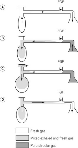
The Mapleson D system with spontaneous respiration
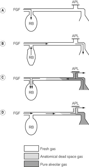
• The first inspiration. An appropriate fresh gas flow (see later) enters as close as possible to the patient end of the breathing system (so as to reduce any apparatus dead space) and the system including the reservoir bag is filled so that during the first inspiration the patient breathes only fresh gas. As the inspiratory rate is greater than the FGF the bag begins to empty (Fig. 5.8A).
• Expiration. During expiration, the exhaled gasses mix with fresh gas entering the system and these pass down the wide bore hose. They initially displace any fresh gas remaining here and start to fill the reservoir bag (Fig. 5.8B). When the bag is full, the remainder of the exhaled gasses and the FGF are voided via the APL (expiratory) valve. Of the expired gasses, it is those from the patient’s respiratory dead space that are voided first, followed by alveolar gasses.
• End-expiratory pause. During the end-expiratory pause the fresh gas flow entering the system passes down the wide bore hose, displacing some of the mixture of exhaled gas and FGF, which is now vented out through the APL valve (Fig. 5.8C). The amount of fresh gas occupying and thus stored in the patient end of the wide bore hose at the end of expiration, therefore depends on the fresh gas flow rate, the duration of the end-expiratory pause, and the degree of mixing (due to turbulence) of the various gaseous interfaces within the corrugated hose.
• At the next inspiration the inhaled gasses consist initially of this stored fresh gas followed then by the mixture of exhaled gasses and FGF that remain in the tube and possibly some of the mixture from the reservoir bag if the inhaled tidal volume is large (Fig. 5.8D).
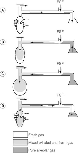
Mapleson D system with controlled or assisted ventilation
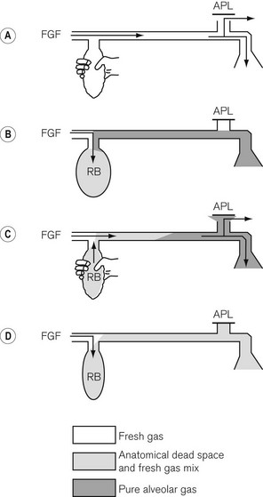
• The first inspiration. As the bag (full of fresh gas) is squeezed, the fresh gas flow entering the system as well as fresh gasses stored in the wide-bore breathing hose pass to the patient. At the same time some gasses from the reservoir bag are lost through the partially open APL (expiratory) valve (Fig. 5.9A).
• Expiration. A mixture of the fresh gas flow and exhaled gasses passes along the hose, eventually entering the now partially deflated reservoir bag, causing it to refill (Fig. 5.9B).
• Expiratory pause. At this point, provided that there is an expiratory pause, the fresh gas supply continues to flow down the hose to replace and drive the mixed gasses out via the APL valve. A longer expiratory pause allows a greater amount of fresh gas to enter the breathing hose (Fig. 5.9C).
• The next inspiration. At the next squeeze of the reservoir bag (Fig. 5.9D) the continuing fresh gas flow, plus the fresh gas now stored in the breathing hose plus any previously expired gasses that may remain in the hose pass to the patient, while some of the mixed gasses within the bag escape via the APL valve. The cycle then repeats itself.
Thus, to prevent rebreathing in the Mapleson D system during both spontaneous and controlled ventilation, the fresh gas flow must be sufficiently high enough to:
• purge the breathing hose of exhaled gasses
• supplement the stored fresh gas in this breathing hose so that any mixed gas in the reservoir bag is prevented from reaching the patient. The amount of fresh gas required will always be greater than the patient’s minute volume and will depend largely on the expiratory pause. The longer the pause, the more effective will be the ability of the fresh gas to purge the breathing hose of expired gas.
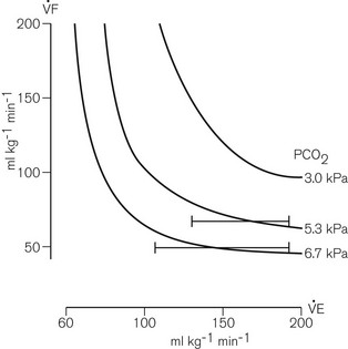
In practice, there is turbulent mixing of the various gaseous interfaces so that alveolar gas is widely distributed (and diluted). Even so, provided sufficiently large controlled minute ventilation is delivered so that most of the fresh gas flow reaches the alveoli, adequate alveolar ventilation will occur with fresh gas flow rates of 70% of the anticipated minute ventilation since, as mentioned above, some rebreathing is acceptable. Fig. 5.10 demonstrates this as well as the fact that the arterial carbon dioxide tension remains fairly constant for any given fresh gas flow rate despite alterations in minute ventilation.
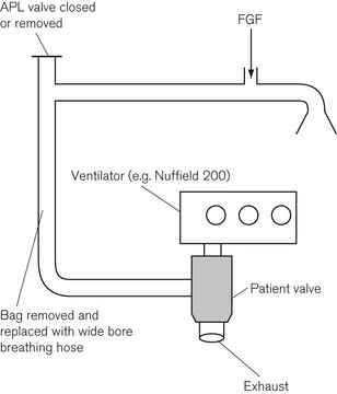
Mapleson D systems are thus able to make efficient use of fresh anaesthetic gasses during controlled ventilation and could have considerable cost saving benefits. Fig. 5.11 shows how the Mapleson D system may be employed with an automatic ventilator. The reservoir bag is removed and replaced with a standard length of corrugated hose of sufficient capacity to accommodate the air or oxygen that is delivered by the ventilator, and therefore prevents it reaching the patient in place of the intended anaesthetic gasses.
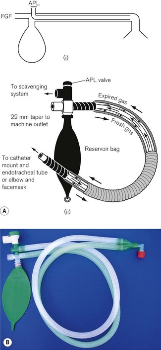
The Bain system
The Bain breathing system (Fig. 5.12) is similar in function to the Mapleson D system. The only difference is that the fresh gas flow is carried by a tube within the corrugated hose (a co-axial arrangement). In the earlier models in particular, there was a risk that the inner tube could become disconnected at the machine end; if this happened a very big dead space was introduced. It could also become kinked, so cutting off the supply of fresh gasses.
Hybrid systems
A number of breathing systems have been described that, by means of a lever switch, can convert the system from a Mapleson A to a Mapleson D or E, allowing a system to be chosen and used in its most efficient mode (i.e. system A, spontaneous respiration; system E, controlled respiration). The Humphrey ADE system (Anaequip) seems to be the most popular version (see Fig. 5.13A). A ‘Y’ shaped length of corrugated breathing hose is attached to H and F in the diagram with the short limb of the Y at the patient.
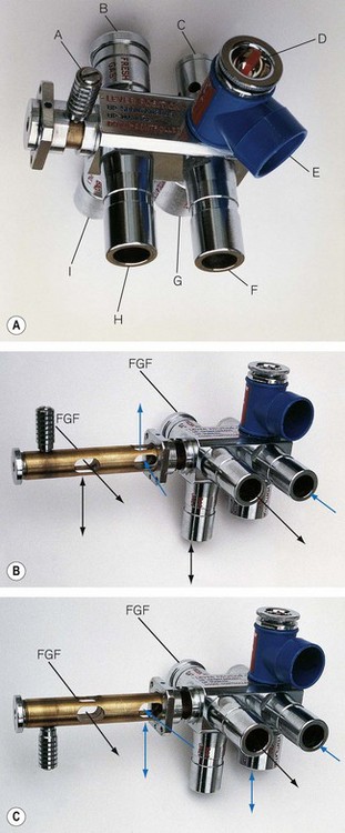
With the lever up in the A mode (Fig. 5.13B), the reservoir bag on the ADE block is connected to the inspiratory pathway as in a Mapleson A system. The breathing hose connecting the block at H to the patient is now designated as the inspiratory limb. Expired gas is carried back along the other limb to the block at F and then is vented through an APL valve which is shrouded to facilitate scavenging. In practice it appears to function more efficiently than a traditional Magill attachment. The improved efficiency is thought to relate to the position and design of the components at the patient end of the system. Towards the end of exhalation in a Magill attachment, the exhaled dead-space gas which has passed up the breathing hose is now returned towards the APL valve by the flushing action of the fresh gas flow entering the system. At the APL valve, it meets and mixes with alveolar gas in turbulent fashion, and a mixture of both is discharged from the valve. However, in the Humphrey (and Lack) systems alveolar gas is diverted in a more laminar fashion into a physically separate expiratory limb, which minimizes any potential for mixing of the two gas phases in question. This arrangement, and the removal of the APL valve assembly away from the patient end of the system, also reduces apparatus dead space, so that with further modification (see below) it may be suitable for infants and neonates.
With the lever down in the D/E mode (Fig. 5.13C), the reservoir bag and APL valve are isolated from the breathing system. What was the ‘inspiratory’ limb in ‘A’ mode now delivers gas to the patient end of the system as in a T-piece (see below). The breathing hose returning gas to the ADE block now functions as the reservoir limb of a T-piece. This hose vents to atmosphere via a port adjacent to the bag mount. As this mode does not incorporate a reservoir bag, it is strictly a Mapleson E system. The port described above is usually connected to a ventilator of the ‘bag-squeezer’ type (see Chapter 9), so that the system can be used in its most efficient mode for controlled ventilation.
• during controlled ventilation, the small tidal volumes required are delivered more efficiently
• during spontaneous respiration, the energy expended by the patient in overcoming the inertia of the gas present in the system is reduced, especially as with high respiratory rates the direction of gas flow is reversed very frequently.
Mapleson E and F systems
The T-piece system
When what are now termed APL valves were first made, they offered a resistance to exhalation, which was deemed unacceptable in certain anaesthetic techniques such as those used for neonatal and infant anaesthesia. This distinction has become less important (see Chapter 12). To avoid this resistance, the T-piece system was designed by Philip Ayre in 1937. In Fig. 5.14 the fresh gasses are supplied via a small-bore tube to the side arm of an Ayre’s T-piece. The main body of the T-piece is within the breathing system and must, therefore, be of adequate diameter. One end of the body is connected by the shortest possible means to the patient. (The volume of this limb makes up apparatus dead space.) The other end is connected to a length of tubing that acts as a reservoir.
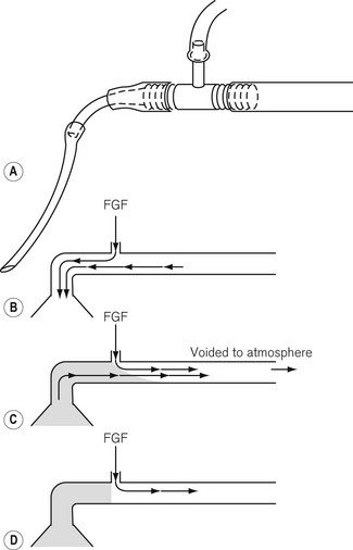
• The diameter of the reservoir limb must be sufficient to present the lowest possible resistance (not more than 0.075 kPa (0.75 cm H20) for a neonate and not more than 0.2 kPa (2 cm H20) for an adult at the appropriate flow rates).
• The volume of the expiratory limb should be not less than the patient’s tidal volume. Too great a volume would matter only in that the greater length would lead to increased resistance. Too great a diameter would lead to altered mixing of the fresh gasses with alveolar gas and to inefficiency of the system. For an adult a standard 110 cm length of corrugated hose is satisfactory.
• The optimum FGF rate depends not only on the patient’s minute volume and respiratory rate, but also on the capacity of the reservoir limb. If the latter is at least that of the patient’s tidal volume, then a rate of 2.5 times the patient’s minute volume is sufficient. This is the most satisfactory arrangement. However, if the capacity of the reservoir is reduced, the flow rate must be increased. If the capacity of the reservoir is reduced to zero, the flow rate must be in excess of the peak inspiratory flow rate so as to reduce the possibility of ingress of air.
Controlled ventilation with the T-piece
Controlled ventilation may be effected by intermittently occluding the end of the reservoir limb with the thumb. This should be done with care, as when the outlet is occluded the full pressure supplied by the anaesthetic machine is applied to the patient. It would seem prudent to include, in infant systems at least, a blow-off valve set to about 4 kPa (40 cm H2O); but this is seldom done. A limitation in its use arises from the fact that the peak inspiratory flow rate is limited to that of the FGF. This is overcome in the Rees modification T-piece, described below.
Non-rebreathing systems utilizing carbon dioxide absorption and recirculation of gasses
• both to purge the system of air and to fill it with fresh anaesthetic agents
• to provide a sufficient amount of inhalational agent for alveolar uptake (which is initially high at the onset of anaesthesia)
• to eliminate exhaled carbon dioxide. (As described previously the efficiency with which this is done depends on the characteristics of the breathing system chosen.)
Carbon dioxide absorption
Carbon dioxide can be removed from exhaled gasses by a chemical reaction with various metallic bases (hydroxides). This reaction requires the presence of water in order that these bases and carbon dioxide (as carbonic acid) can exist in ionic form.
Chemical composition of absorbents
Water content


The reaction is interesting in that:
• it produces heat energy (it is an exothermic reaction)
• it changes the pH of the soda lime, which allows the use of indicator dyes to show when the absorbent is exhausted
• it produces more water than that used up in the reaction. In fact, for each mole of carbon dioxide absorbed one mole of water is produced.
Other constituents
Zeolite
• Porosity of the mixture. The absorbent behaves more efficiently as it becomes more porous due to the increase in available surface area
• Hardness. The harder the mixture the less likely it is to form dust. This may be carried around the breathing system and is caustic if inhaled. It may also become damp and settle on valves within the breathing system and cause them to become sticky
• Water content. Zeolite also helps to prevent the drying out of the absorbent in adverse conditions. However, should this occur, the zeolite may start to absorb volatile anaesthetic thereby reducing the concentration in the breathing system especially at the beginning of an anaesthetic. Up to 80% of the agent may be absorbed in this situation.
The exothermic reaction
• If the fresh gas flow rate is high, the dry gas entering the system reduces both the humidity and the temperature of the recirculating gas.
• At low fresh gas flows, if the gas circulation time is high, the humidity and temperature rises.
• The longer the system is in use at low fresh gas flows, the greater the humidity and temperature of the circulating gas.
• Trichloroethylene can be decomposed to dichloroacetylene (which is neurotoxic) and further to phosgene, if the temperature within the product exceeds 60oC. Older anaesthetic machines often incorporated a switching system on the back bar that could divert gas directly into a circle system rather than to the common gas outlet. The trichloroethylene vaporizer (where fitted) was always positioned downstream of this switch so that it could never be used with the circle absorber system.
• Anaesthetic agents with the CHF2 moiety (desflurane, enflurane and isoflurane) react with dry, warm soda lime or barium lime (Baralyme) to produce varying amounts of carbon monoxide (Table 5.1).
Table 5.1 Carbon monoxide production by reaction of anaesthetic agents that have the CHF2 moiety (desflurane, enflurane, isoflurane) with lime
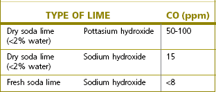
Dry barium lime, which contains potassium hydroxide, has a much greater tendency to produce carbon monoxide than dry soda lime that contains sodium hydroxide. Fresh absorbent, which has an approximately 15% water content, appears to prevent carbon monoxide formation. In fact significant production takes place only when the water content drops below 2%. The problem can occur when the absorber is left unused for long periods, or when large amounts of dry gas are allowed to pass through it between cases, particularly overnight or at weekends. Even with the flow meters turned off, this is seen albeit after a long period of time in some anaesthetic machines, if:
• They are plugged into the pipeline supply
• They have a minimal basal flow of oxygen through the machine
• The absorber is so constructed that fresh gas flows through the absorbent prior to entering the inspiratory limb.
• using smaller absorbers (so that the contents have to be changed regularly)
• disconnecting them when possible
• only having breathing system designs that allow the fresh gas inflow to bypass the absorbent, and unplugging machines from the pipeline supply when not in use for extended periods.
• failed induction or inadequate anaesthetic depth
• clinical sign of airway irritation
• oxygen desaturation, increased airway pressures
In summary the recommendations for preventing the problem are as follows:
• If there is any suspicion that the absorbent has not been in use for an extended period of time it should be replaced.
• The machine should be turned off when not in use so that there is no flow of gas through the absorber.
• The vaporizers should be turned off when not in use.
• The sevoflurane concentrations dialled up on the vaporizer and that measured by an analyzer should be compared and any major disparity should be investigated.
• A check for excessive heat production from the absorbent should be performed periodically.
Classification of breathing systems utilizing carbon dioxide absorption
Carbon dioxide absorption can be used in two types of system:
’To-and-fro’ absorption systems
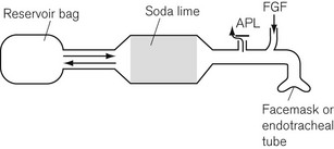
The Waters’ canister (Fig. 5.16)
Here the patient breathes in and out of a closed bag, which is connected to the facemask or endotracheal tube via a canister containing soda lime. The part of the system between the patient and the soda lime is dead space and, therefore, its volume must be kept to a minimum. This means that the soda lime canister must be close to the patient’s head, and this leads to practical difficulties. A length of wide-bore tubing may, however, be interposed between the canister and reservoir bag without detriment. The fresh gasses are introduced at the patient end of the system, and the expiratory valve is usually mounted close by, though it may equally well be put at the bag end. The canister is usually placed in the horizontal position for convenience, and it is most important that it is well packed, since if there were a space above the soda lime, ‘channelling’ would occur and absorption would be incomplete (Fig. 5.17A).
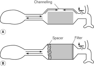
Canisters are available as pre-packed, disposable units. In those intended for reuse, the absorbent may conveniently be compressed to prevent gaps by the insertion of a spongy ‘spacer’ at one end (Fig 5.17B). When the canister is closed, the sealing washer should be checked to ensure that it is in the correct position and any soda lime on the threads of the canister or the sealing washer should be carefully removed as these may cause leaks. The whole system should be tested before use.
Circle absorption systems
Here the disadvantages of the absorbent canister being so close to the patient are avoided. The patient is connected to the absorber by two corrugated hoses, one inspiratory and the other expiratory, as shown in Fig. 5.18A. The one way or ‘circle’ flow of gasses through the system is determined by two unidirectional valves V1, and V2, which are accommodated in transparent domes so that their correct action may be observed.
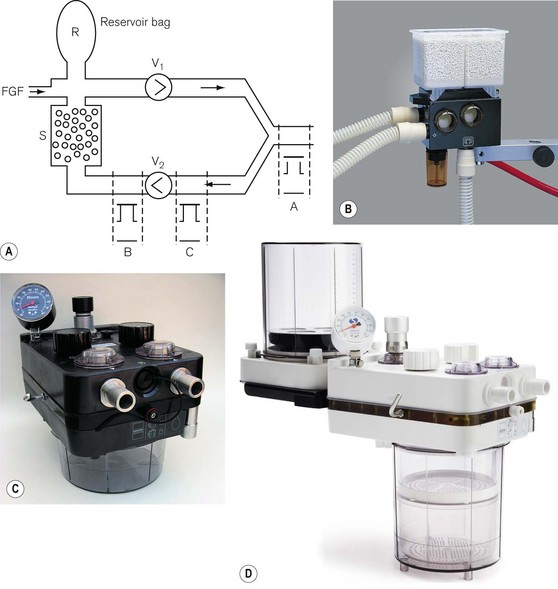
The fresh gas port and the reservoir bag may be sited in the inspiratory pathway close to the inspiratory valve V1 or in the expiratory limb of the system downstream of the valve V2. There are claimed advantages for each arrangement. Positioning the FGF and bag in the inspiratory pathway may reduce the resistance to inspiratory effort and prevents desiccation of the absorbent if the fresh gas flow is left on for long periods when the system is not in use. This has implications for the efficiency of the absorbent and its potential for producing unusual breakdown products (see above). However, positioning the FGF and bag in the expiratory limb so that the FGF passes through the absorbent before reaching the patient allegedly warms and humidifies this gas. This also seems to remove some of the excess moisture often seen in absorbers that might increase resistance through the system. The APL valve is usually mounted downstream of the valve V2 (position ‘B’) in the expiratory limb, but before gas entry into the absorber. Here, it can dump excess exhaled gas prior to entry of gas into the absorber. At one time it was considered that an APL valve was best positioned in the breathing system at position ‘A’ for use with spontaneous respiration (Fig. 5.18A). This would preferentially dump alveolar gas during exhalation, thus increasing carbon dioxide elimination upstream of the absorber and conserving soda lime. However, as scavenging assumed a greater importance, the inconvenience of connecting a cumbersome scavenging hose to a valve in this position has limited its usefulness.
Circle breathing systems are manufactured in many different designs and sizes. Most are two part systems with one part comprising a fixed body containing the gas pathways, switches, valves and the other a detachable canister that contains the absorbent. Figs 5.18B, C and D show commercial versions of the system described. Fig. 5.18B (circle system for ADU anaesthetic machine, Datex-Ohmeda) has a container for 1 kg of absorbent that may be either disposable or refilled. During replacement, self-sealing valves on the body of the unit close to prevent escape of patient gas from the rest of the system. Figs 5.18C and D show other types of 1 kg and 2 kg absorber respectively. The rationale for larger absorbers is discussed below.
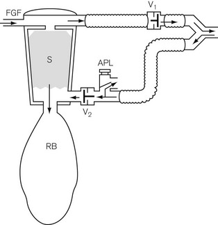
The system shown in Figs 5.19A and B is a disposable version. The valve V1 is sited in the breathing hose and as close to the patient as possible. In this position it is alleged to have a faster response to pressure changes caused by exhalation and closes earlier, although, as it is exhaled dead space gas that enters the system first, it is immaterial as to which limb this enters initially. Unlike many circle systems that are now an integral part of the anaesthetic workstation, the APL valve is not automatically excluded from the system in mechanical ventilation mode. Therefore, when a ventilator is attached to the reservoir bag port and is in use, the APL valve must be closed fully or gas will be lost from the system.
Flow resistance
• A high fresh gas flow will assist flow in the inspiratory side of the system, thus decreasing any inspiratory resistance, but increasing expiratory resistance through the unidirectional and APL (expiratory) valves.
• The reverse occurs with low gas flows. Low fresh gas flow rates will also increase the relative humidity and thus increase the ‘stickiness’ of the unidirectional valves owing to water vapour condensation; therefore further increasing flow resistance.
• The flow rates developed by rapid respiratory excursion (tidal volume and rate) produce the greatest swings in flow resistance (see Table 5.2). These factors may not matter in healthy adults, but they can be unacceptable in young children.
Table 5.2 Flow resistance in circle breathing systems
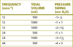
Reproduced from Young TM. Carbon dioxide absorber Anaesthesia 1971;26:78. With permission.
Efficiency of absorbers
The efficiency of carbon dioxide absorption in a canister depends on:
• the freshness, composition and the available surface area of the absorbent (see above)
• the length of time the gas to be treated is in contact with the granules.
With the recent introduction of routine expired carbon dioxide monitoring, these last two considerations appear to be less of a problem in clinical practice, and the reintroduction of smaller absorbers may well have advantages. These are easier to maintain, use and keep clean, and they have fewer leaks and are less prone to causing degradation of volatile agents (see above). The absorbent can also be supplied in disposable cartridges (see Fig. 5.18B).
Absorber switch
Some newer European and American models omit this switch. The rationale for excluding this switch involves safety considerations. Omitting the switch erases the possibility of its inadvertently being left in the absorber bypass mode. However, the routine use of carbon dioxide monitoring in any case lessens this danger.
The use of ventilators with circle systems
Any ventilator deemed suitable for use with a circle system must have the following features:
• It must be able to reproduce the effect of manual compression and refilling of the reservoir bag, i.e. it must have a single breathing hose inlet/outlet to allow to and fro movement of gas.
• It must have a valve to release any excess gas in the circle system during the exhalation phase.
• It must have a power source that is independent of the fresh gas entering the circle system so that a minute ventilation can be delivered that is larger than the fresh gas flow (especially when this is set at low flows).
• If the ventilator is gas powered, this driving gas should not be able to contaminate the respirable gas reaching the patient.
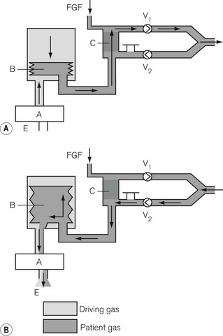
‘Bag squeezer’
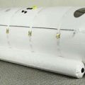
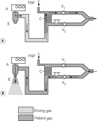
Here, the reservoir bag is replaced by a bellows that may be compressed mechanically (see Figs 9.7E and F) or pneumatically (Fig. 5.20). In the latter the bellows is enclosed in a gas-tight container and the driving gas that enters the container then compresses the bellows, but does not mix with the patient gas contained within it.
‘Pneumatic piston’
Here, the reservoir bag is replaced by a suitably long length of breathing hose. The driving gas from the ventilator is passed through a special valve (Figs 5.21A and B) into the breathing hose. The latter is sufficiently long so that its internal volume is at least 1.5–2 times greater than the patient’s tidal volume and prevents the driving gas from entering the circle and contaminating the patient gas. This is especially important in many circle systems where the reservoir limb is sited in the inspiratory pathway. Here, driving gas could dilute the inspiratory anaesthetic gas sufficiently to cause an inadequate level of anaesthesia to be maintained.
Mechanical ventilation in circle systems
Control of minute ventilation
The ventilator and circle breathing systems in modern workstations are integrated. The tidal volume that is intended is entered on the ventilator control panel and is delivered to the patient. Transducers monitor the flow to the patient and make adjustments for changes in compliance, resistance and alterations in fresh gas flow so that the tidal volume remains the same.
Consider the following for a FGF entering the circle system:


Maintenance of circle absorber systems
The absorbent should be changed at regular intervals either when:
Gas and vapour concentration in a circle system
In practice the fresh gas flow is usually reduced in stages.
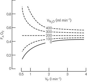
Oxygen concentrations in circle systems at low fresh gas flows
Fig. 5.22 shows the decrease in alveolar oxygen concentrations of a 50% nitrous oxide and 50% oxygen mixture under controlled conditions. It can be seen that at a FGF of 1 l min−1 if there is no longer any nitrous oxide uptake, the oxygen concentration has dropped to 27% and drops even further at a FGF of 0.5 l min−1. Therefore, in clinical practice the oxygen concentration in a circle at low flows is unpredictable and monitoring of inspired oxygen with an analyzer is essential. In fact, monitoring of all gasses and anaesthetic vapours should be considered mandatory for circle systems at low flows.
Vaporizer outside circle
• Expired gas, which is recycled (and which has a reduced concentration of inhalational agent due to uptake), dilutes the FGF within the system. This reduces the delivered concentration of inhalational agent to below that anticipated by the dial setting on the vaporizer.
• At a low FGF, vaporizer efficiency may well be altered, providing a lower or higher than expected concentration of inhalational agent. This is not a problem in modern vaporizer performance but was seen with models that are now obsolete.
Vaporizer in circle
• The fresh gas flow. The lower the FGF, the greater will be the recirculation of gas already carrying vapour and the higher will be the concentration of inspired agent.
• The efficiency of the vaporizer. The more efficient the vaporizer the higher will be the inspired concentration of agent. This has important implications with potent inhalational agents. At a low FGF and a large assisted or controlled minute ventilation, the anaesthetic gas may well become saturated with agent at that temperature. For halothane, this will represent a concentration of 33% at 21°C (the saturated vapour pressure for halothane).
Breathing systems with assisted circulation
It has long been appreciated that part of the energy required to propel the gasses along the passages of a breathing system must be derived from the patient’s respiratory effort. The latter, prejudiced by the depressant effects of narcosis, can become inefficient, and any form of resistance would further impair respiratory function. On the other hand, any form of assistance to flow or of reduction of resistance would be beneficial. To this end various ‘circulators’ had been devised in the past although none of these has persisted through to modern usage. However, there is renewed interest in this facility and the Dräger Zeus (see Chapter 4, The anaesthetic workstation) now sports an electronically driven turbine.
Inspiratory assistance
Some of the more sophisticated anaesthetic machines, with integral ventilators and circle systems, may have sensors in the breathing system which detect a patient’s inspiratory effort and trigger the ventilator to supplement it (a pressure support mode). This is discussed further in Chapter 9.
Procedures for checking breathing systems
• was either unfamiliar with the equipment,
• included a non-standard item,
• had not noticed that it had been assembled incorrectly,
• had not noticed that it had developed a fault, or
• had not noticed that the lumen of the system at some point had been occluded by a foreign body.
• the components of the system chosen for use (especially if they are not from the same manufacturer) always conform to the same national or international standard
• the components are assembled appropriately
• all tapered connections are secure using a push and twist technique
• with the APL valve closed, and the patient end occluded, the system is gas-tight when filled and that gas subsequently escapes when the occlusion is removed
• when the patient end is occluded for a second time and the APL valve is opened, the gas escapes easily through it.
The components of a breathing system
Rebreathing and reservoir bags
Rebreathing and reservoir bags (Fig. 5.23) are identical, the distinction being solely in the use to which they are put, as explained previously. The commonly used size in adult breathing systems is 2 L (i.e. that which when fully, but not forcibly, distended has a capacity of 2 L; in clinical practice it is seldom filled beyond this capacity). They are also available in 1 L and 0.5 L sizes for paediatric anaesthesia. Larger bags are sometimes used as reservoir bags in ventilators.
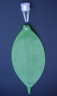
In adult breathing systems, the capacity to which the bag may easily be distended must exceed the patient’s tidal volume. A larger capacity, bag (2 L), however, is safer as it more easily absorbs pressure increases. The neck of the bag is stretched over a female 22 mm metal or plastic tapered connector. A metal or plastic cage is often attached to the part of the connector that fits inside the bag. This prevents the inlet from being occluded if the bag were folded.
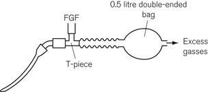
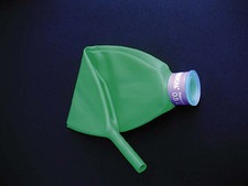
In the Jackson Rees T-piece paediatric attachment, a double-ended bag is added to the expiratory limb (Fig. 5.24) and the smaller end acts as an expiratory port, the aperture of which can be controlled by the anaesthetist.
Adjustable pressure limiting (APL) valves
The operating principles of APL valves are based on the Heidbrink valve (Fig. 5.25). The valve disc is as light as possible, and rests on a ‘knife-edge’ seating that presents a small area of contact. This lessens the tendency to adhesion between the disc and seating due to the surface tension of condensed water from the expired air, or after washing or sterilizing. The disc has a stem that is located in a guide, in order to ensure that it is correctly positioned on the seating, and a lightweight coiled spring, which promotes closure of the valve.
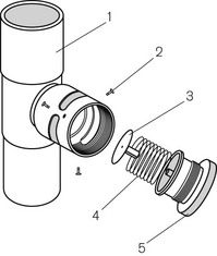
Figure 5.25 The Heidbrink valve: 1, male tapers at both ends; 2, retaining screws; 3, disc; 4, spring; 5, valve top.
The Humphrey APL valve
An interesting addition to the standard APL valve is the modification seen on the version (Figs 5.13 and 5.26) that is part of the Humphrey ADE system. Here, the valve disk is attached to a red-coloured spindle that extends through the valve top. When the valve is fully open, the spindle is seen to bob up and down as the disk is lifted up and down during respiration. The valve top is made concave and shiny so that it reflects and magnifies the spindle colour so as to detect even the smallest movement when used in paediatric anaesthesia. The inside of the valve body has a small funnel through which the disk has to move before significant gas can escape. This initial movement of 5 mm accentuates the bobbing action of the spindle which is useful particularly in paediatric anaesthesia.
• As there is no leak from the valve during inspiration, the patient’s lung compliance may be more accurately assessed.
• It becomes as efficient as the Mapleson ‘A’ mode in spontaneous respiration (i.e. the valve is shut during inspiration and open during expiration).
• The valve top may be kept in the ‘open’ position at all times and does not require repeated adjustment when switching between spontaneous and manual ventilation.
APL valves with in-built overpressure safety devices
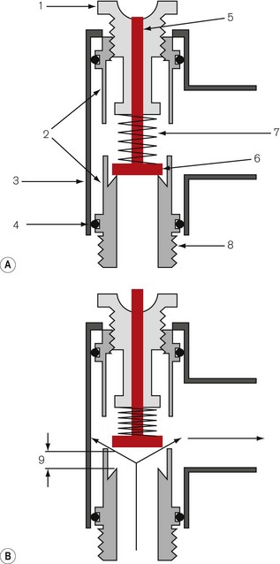
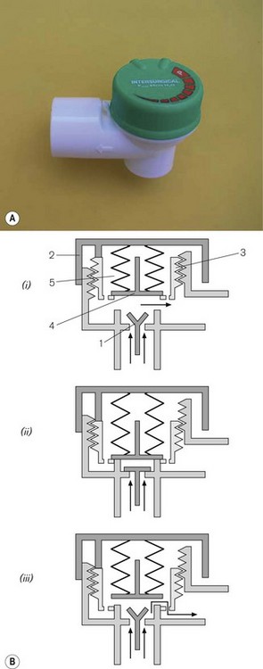
An example, is shown in Figure 5.27.
• the inner (3), which is tensioned with a weak spring (4)
• the outer (5), which is tensioned with a more powerful one (2).
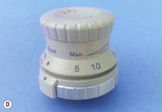
When the valve top (1) is unscrewed fully (Fig. 5.27A), the outer valve is permanently open, but the inner one is closed until exhaled gas forces it open. The pressure required to do this is small (0.15 kPa /1.5 cm H2O). As the valve is gradually closed, the expiratory flow resistance increases and in sophisticated examples this resistance can be calibrated and displayed on the valve body. When the valve top is screwed down fully, both valves are closed and in this position the outer one is pushed against the inner so that is has no movement of its own (Fig. 5.27B). An excess pressure is now required to move the more powerful spring on the outer valve which will begin to open at 3 kPa (30 cm H2O) and be fully open between 6 and 7 kPa (60–70 cm H2O) when the gas flow is 50 l min−1 (Fig. 5.27C). Fig. 5.27D is an example of a calibrated APL valve incorporating an overpressure safety valve set at 70 cm H2O.
Alternative APL valve design
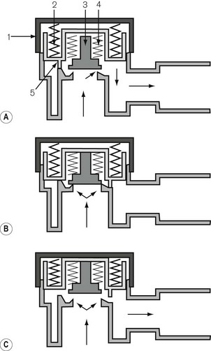
Many breathing systems are now supplied as single use items. This includes the APL valve (Fig. 5.28A). It is now possible to simplify the design so that the spring and the valve disc are replaced by a neoprene flap valve (1) (Fig. 5.28Bi). This opens and shuts in the normal manner during spontaneous respiration. When positive pressure is required, the valve top (2) operates a screw threaded insert (3) that lowers an overpressure relief valve (4). As the valve top is screwed shut, the insert lowers the second valve (4) onto the flap valve housing, gradually occluding the expiratory pathway until complete occlusion occurs (Fig. 5.28Bii). The second valve is fitted with a spring (5) which is strong enough to maintain the occlusion up to a pressure of 60 cm H2O, but weak enough for the valve to lift (Fig. 5.28Biii) and allow gasses at a higher pressure to escape.
Breathing hoses
The most commonly used type was for a long-time, corrugated hose of rubber or polychloroprene (neoprene). The corrugations allow acute angulations of the hose without kinking. The advantage of these materials is that the ends are more easily stretched, and will make a good union with other components of different diameters. They may be sterilized by steam autoclaving and be reused in countries where single-use alternatives are impractical. The disadvantages are that the irregular wall must cause turbulence and being opaque may harbour dirt and infection unseen. They are also heavy and, if unsupported, may drag on a facemask or endotracheal tube.
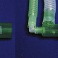
Various other materials such as silicone rubber and plastics (polyethylene) are in use, both in corrugated and smooth form (Fig. 5.29). Smooth bore breathing hose produces less turbulence than the corrugated variety at similar gas flows. It can also be produced so that it resists kinking (by the attachment of a reinforcing spiral of a similar material to its external surface). With smooth bore hosing, a smaller diameter (e.g. 15 mm) may well be acceptable for use with adult breathing systems (see Humphrey ADE breathing system).
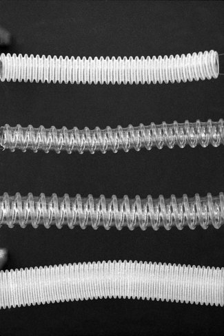
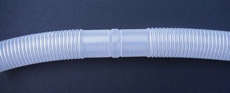
Plastic hosing has become very popular because it is lightweight, cheap to manufacture, and, therefore, disposable. Some are supplied as complete breathing systems (Figs 5.12 and 5.19) or in long coils, the appropriate length of which may be cut off at one of the frequent intervals where the corrugations (Fig. 5.30) give way to a shaped connector. More recently, the addition of small quantities of silver mixed with the plastic (Silver Knight) has been used to make breathing systems bactericidal both on the inside and the outside of the hosing.
There are several standard sizes of corrugated hose, both ends of which have smooth walls for about 2–3 cm. These ends are designed to fit either tapered connectors (see below) or tapered components of a breathing system. The breathing hose for adult use is normally 22 mm wide so as to reduce the resistance to breathing to a minimum. Paediatric breathing hose has a narrower bore (15 mm) to reduce its internal volume (see Chapter 12) and to make it less cumbersome.
Tapered connections (adapters)
Examples of tapers are shown in Figs 5.31A and B.
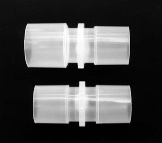
Figure 5.31 Plastic (disposable) 22 mm tapered adaptors. (Top) Female to male; the male part is normally inserted into each end of a breathing hose. (Bottom) Male to male; this is inserted into the distal end of a piece of corrugated tubing when used as an extension for a reservoir bag (Fig. 5.32C).
The current ISO and BS recommendations on the sequence of tapers in various breathing systems are set out in Fig. 5.32.
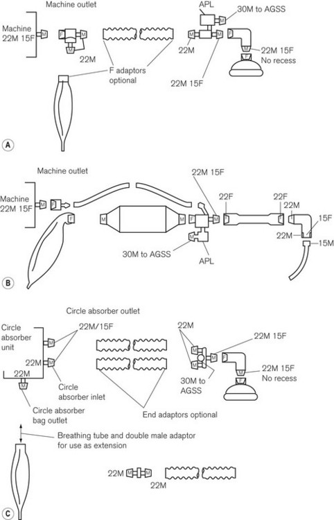
Figure 5.32 Current sequence of tapers in anaesthetic breathing systems as recommended by the ISO and BSI (BS 3849) as from 1988 and maintained in BS EN ISO 5356-1: 2004. Typical layout of A. Mapleson A system; B. to-and-fro absorption system; and C. circle absorption system. M, male conical fitting; F, female conical fitting; APL, adjustable pressure-limiting valve.
• 30 mm tapered connections for the attachment of scavenging hose to breathing systems
• 22 mm tapers for connections within a breathing system
• 15 mm connections for the attachment of a breathing system to an endotracheal tube.
It is worthy of note that the current British Standard requires that a reservoir bag should have a female inlet to fit the male outlet for bag mounts on all breathing systems. However, should a length of breathing hose be required between the bag mount and reservoir bag, a problem arises. The breathing hose is manufactured with two female ends. One will fit the bag mount (male to female) but the other will not fit the bag (female to female). A male to male 22 mm tapered adapter is required (see Fig. 5.31).
Classification of breathing systems
Cook LB. Mapleson breathing systems. The importance of the expiratory pause. Anaesthesia. 1996;51:453–460.
Dorrington KL. The Mapleson breathing systems. Anaesthesia. 1996;51:988.
Mapleson WW. The elimination of rebreathing in various semi-closed anaesthetic systems: 1954. Br J Anaesth. 1998;80:263–269.
Mapleson WW. Editorial I: Fifty years after – reflections on ‘The elimination of rebreathing in various semi-closed anaesthetic systems. Br J Anaesth. 2004;93:319–321.
Miller DM. Breathing systems reclassified. Anaesth Intensive Care. 1995;23:281–283. 8
Chan AS, Bruce WE, Soni N. A comparison of anaesthetic breathing systems during spontaneous ventilation. An in-vitro study using a lung model. Anaesthesia. 1989;44:194–199.
Ooi R, Pattison J, Soni N. The additional work of breathing imposed by Mapleson A systems. Anaesthesia. 1993;48:599–603.
Ooi R, Lack A Soni N, Whittle J, Pattison J. The parallel Lack anaesthetic breathing system. Anaesthesia. 1993;48:409–414.
Adams AP. The Bain circuit. Prevention of anaesthetic mixture dilution when using mechanical ventilators delivering non-anaesthetic gasses. Anaesthesia. 1977;32:46–49.
Henville ID, Adams AP. The Bain anaesthetic system. Anaesthesia. 1976;31:247–256.
Spoerel WE, Bain JA. Anaesthetic breathing systems. Br J Anaesth. 1986;58:819–821.
Rebreathing with Mapleson systems
Barrie JR, Beatty PC. Rebreathing and semiclosed anaesthetic breathing systems. Anaesthesia. 1993;48:86–87.
Cook LB. Rebreathing in the Mapleson A, C and D breathing systems with sinusoidal and exponential flow waveforms. Anaesthesia. 1997;52:1182–1194.
Dorrington KL, Lehane IR. Rebreathing during spontaneous and controlled ventilation with ‘T’ piece breathing systems: a general solution. Anaesthesia. 1989;44:300–302.
Dorrington KL, Lehane JR. Minimum fresh gas flow requirements of anaesthetic breathing systems during spontaneous ventilation: a graphical approach. Anaesthesia. 1987;42:732–737.
Resistance to flow with Mapleson systems
Kay B, Beatty PC, Healy TE, Accoush ME, Calpin M. Change in the work of breathing imposed by five anaesthetic breathing systems. Br J Anaesth. 1983;55:1239–1247.
Martin DG, Kong KL, Lewis GT. Resistance to airflow in anaesthetic breathing systems. Br J Anaesth. 1989;62:456–461.
Humphrey D. A new anaesthetic breathing system combining Mapleson A, D & E principles. Anaesthesia. 1983;38:361–372.
Humphrey D. The ADE anaesthetic breathing system. Anaesthesia. 1984;39:715–716.
Humphrey D, Brock-Utne JG, Downing JW. Single lever Humphrey ADE lowflow universal anaesthetic breathing system. Part II: Comparison with Bain system in anaesthesized adults during controlled ventilation. Can Anaesth Soc J. 1986;33:710–718.
Orlikowski CEP, Ewart MC, Bingham RM. The Humphrey ADE system: evaluation in paediatric use. Br J Anaesth. 1991;66:253–257.
Shaw M, Scott DH. Performance characteristics of a ‘to and fro’ disposable soda lime canister. Anaesthesia. 1998;53:454–460.
Levels of anaesthetic agents in circle systems
Conway CM. Gaseous homeostasis and the circle system. Validation of a model. Br J Anaesth. 1986;58:337–344.
Cook LB, Chakrabarti MK. Circle systems with a coaxial inspiratory limb. Investigation with a lung model. Anaesthesia. 1996;51:247–254.
Mapleson WW. The concentration of anaesthetics in closed circuits, with special reference to halothane. Br J Anaesth. 1960;32:298–309.
Mapleson WW. The theoretical ideal fresh-gas flow sequence at the start of low-flow anaesthesia. Anaesthesia. 1998;53:264–272.
Sobreira DP, Jreige MM, Saraiva R. The fresh-gas flow sequence at the start of low-flow anaesthesia. Anaesthesia. 2001;56:379–380.
Sobolev I, Sellers WF. Rate of change in gas concentrations in a charged circle system with absorber. Anaesthesia. 2001;56:380–381.
Wright D, Brosnan S, Royston B, White D. Controlled ventilation using isoflurane with an in-circle vaporiser. Anaesthesia. 1998;53:650–653.
Coetzee JF, Stewart LJ. Fresh gas flow is not the only determinant of volatile agent consumption: a multi-centre study of low-flow anaesthesia. Br J Anaesth. 2002;88:46–55.
Cossham PS. Obstruction to wet soda lime granules. Anaesthesia. 1992;47:10–11.
Knolle E, Linert W, Gilly H. The color change in CO2 absorbents on drying: an in vitro study using moisture analysis. Anesth Analg. 2003;97:151–155.
Murray JM, Renfrew CW, Bedi A, McCrystal CB, Jones DS, Fee JP. Amsorb: a new carbon dioxide absorbent for use in anesthetic breathing systems. Anesthesiology. 1999;91:1342–1348.
Carbon monoxide and compound A formation
Baum JA, Woehlckhemical JH. Reaction interaction of inhalation anaesthetics with CO2 absorbents. Best Pract Res Clin Anaesthesiol. 2003;17:63–76.
Baxter PJ, Garton K, Kharasch ED. Mechanistic aspects of carbon monoxide formation from volatile anesthetics. Anesthesiology. 1998;89:929–941.
Cunningham DD, Huang S, Webster J, Mayoral J, Grabenkort RW. Sevoflurane degradation to compound A in anaesthesia breathing systems. Br J Anaesth. 1996;77:537–543.
Fang ZX, Eger EI, 2nd. USCF Research shows that CO comes from CO2 absorbent. Anaesth Patient Saf Found Newsl. 1995;9:26–29.
Fang ZX, Eger EI, 2nd., Laster MJ, Chortkoff BS, Kandel L, Ionescu P. Carbon monoxide production from degradation of desflurane, enflurane, isoflurane, halothane, and sevoflurane by soda lime and Baralyme. Anesth Analg. 1995;80:1187–1193.
Funk W, Gruber M, Wild K, Hobbhahn J. Dry soda lime markedly degrades sevoflurane during simulated inhalation induction. Br J Anaesth. 1999;82:193–198.
Harrison N, Knowles AC, Welchew EA. Carbon monoxide within circle systems. Anaesthesia. 1996;51:1037–1040.
Knolle E, Heinze G, Hermann G. Small carbon monoxide formation in absorbents does not correlate with small carbon dioxide absorption. Anesth Analg. 2002;95:650–655.
Knolle E, Linert W, Gilly H. The color change in CO2 absorbents on drying: an in vitro study using moisture analysis. Anesth Analg. 2003;97:151–155.
References Medicines Control Agency Drug Alert 1995 (N31 May EL(95) (ALERT) A/17) Important precautions required when using halogenated anaesthetic agents. 1995;78:340–8.
Stabernack CR, Brown R, Laster MJ, Dudziak R, Eger EI, 2nd. Absorbents differ enormously in their capacity to produce compound A and carbon monoxide. Anesth Analg. 2000;90:1428–1435.
Strum DP, Edmond I, Eger II. Degradation, absorption and solubility of volatile anaesthetics in soda lime depend on water content. Anesth Analg. 1994;78:340–348.
Struys MM, Bouche MP, Rolly G, Vandevivere YD, Dyzers D, Goeteyn W, et al. Production of compound A and carbon monoxide in circle systems: an in vitro comparison of two carbon dioxide absorbents. Anaesthesia. 2004;59:584–589.
Woehlck HJ, Dunning MB, 3rd., Kulier AH, Sasse FJ, Nithipataikom K, Henry DW. The response of anesthetic agent monitors to trifluoromethane warns of the presence of carbon monoxide from anesthetic breakdown. J Clin Monit. 1997;13:149–155.
Yamakage M, Kimura A, Chen X, Tsujiguchi N, Kamada Y, Namiki A. Production of compound A under low-flow anesthesia is affected by type of anesthetic machine. Can J Anaesth. 2001;48:435–438.
Abnormal heat generation in circle systems
Castro BA, Freedman LA, Craig WL, Lynch C. Explosion within an anesthesia machine: Baralyme(R), high fresh gas flows and sevoflurane concentration. Anesthesiology. 2004;101:537–539.
Fatheree RS, Leighton BL. Respiratory distress syndrome after an exothermic Baralyme(R)–sevoflurane reaction. Anesthesiology. 2004;101:531–533.
Laster M, Roth P, Eger EI, 2nd. Fires from the interaction of anesthetics with desiccated absorbent. Anesth Analg. 2004;99:769–774.
Wu J, Previte JP, Adler E, Myers T, Ball J, Gunter JB. Spontaneous ignition, explosion, and fire with sevoflurane and barium hydroxide lime. Anesthesiology. 2004;101:534–537.
Blanshard HJ, Milne MR. Latex-free reservoir bags: exchanging one potential hazard for another. Anaesthesia. 2004;59:177–179.
Department of Health. Anaesthetic and respiratory equipment: the use of 22 mm breathing system connections. Safety Action Bulletin. 1989.
Medical Devices Agency (MDA). DB 9501 Reuse of Medical devices supplied for single use only. Reuse of Equipment Intersurgical Technical Bulletin TB. 1995;5(4):95.