Mechanical Ventilators
After reading this chapter you will be able to:
 Discuss the basic design features of ventilators.
 Classify ventilators and describe how they work.
 Define what constitutes a mode of ventilation.


To initiate and manage a mechanical ventilator safely and effectively, the respiratory therapist (RT) must thoroughly understand (1) ventilator design, classification, and operation; (2) appropriate clinical application of ventilatory modes (i.e., the proper matching of ventilator capability with physiologic need); and (3) the physiologic effects of mechanical ventilation, including gas exchange and pulmonary mechanics. This chapter focuses on the first and second of these. This chapter explains classification terminology and outlines a framework for understanding current and future ventilatory support devices.1–3 For the application of ventilators, the specific indications and clinical use of the various modes of full and partial ventilatory support are outlined.
How Ventilators Work
To understand how ventilators work, one must have some knowledge of basic mechanics. A ventilator is simply a machine, which is a system designed to alter, transmit, and direct applied energy in a predetermined manner to perform useful work.4 Ventilators are provided with energy in the form of either electricity or compressed gas. The energy is transmitted or transformed (by the drive mechanism of the ventilator) in a predetermined manner (by the control circuit) to augment or replace the patient’s muscles in performing the work of breathing (the desired output). To understand mechanical ventilators, the following four basic functions of ventilators must be understood:
 Rule of Thumb
Power Transmission and Conversion
Drive Mechanism
The drive mechanism of the ventilator converts the input power to useful work. The characteristic flow and pressure patterns the ventilator produces are determined in part by the type of drive mechanism it contains. Drive mechanisms can be either (1) a direct application of compressed gas via a pressure-reducing valve or (2) an indirect application via an electrical motor or compressor. Descriptions of these devices are provided in textbooks devoted to respiratory care equipment.6
Output Control Valve
The output control valve regulates the flow of gas to the patient. It may be a simple on/off exhalation valve, as in the Newport E100i (Newport NMI Ventilators; Newport Medical Instruments, Newport Beach, CA). Alternatively, the output control valve can shape the output waveform, as in the Maquet SERVO-i (Maquet, Bridgewater, NJ). Commonly used output control valves include the pneumatic diaphragm, electromagnetic poppet/plunger valve, and proportional valve.6
Control System
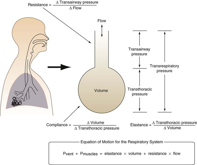
Knowledge of the mechanics of breathing provides a good foundation for understanding how ventilators work. Specifically, the pressure needed to drive gas into the airway and inflate the lungs is important. The formula that relates these variables is known as the equation of motion for the respiratory system (Figure 42-1):7
< ?xml:namespace prefix = "mml" />
 Equation 42-1, A
 is flow (usually zero unless auto-PEEP is present). Auto-PEEP is the difference between end expiratory airway pressure and end expiratory lung pressure. The combined muscle and ventilator pressures cause gas to flow into the lungs. Elastance (elastance = Δpressure/Δvolume) and resistance (resistance = Δpressure/Δflow) together constitute the impedance or load against which the muscles and ventilator do work. The equation of motion is sometimes expressed in terms of compliance (compliance = Δvolume/Δpressure) instead of elastance.
 are constant because of the preset values of tidal volume and inspiratory flow, as auto-PEEP increases, peak inspiratory pressure increases. For pressure control ventilation, the airway pressure waveform is constant because of the preset value of inspiratory pressure. As auto-PEEP increases, both inspired tidal volume and peak inspiratory flow decrease. If inspiration is unassisted (PVENT = 0), the equation shows that PMUS must exceed auto-PEEP before inspiratory flow can begin. If the patient is connected to a ventilator, P
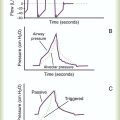
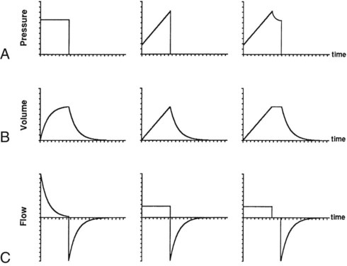
Pressure, volume, and flow all are changeable variables measured relative to their baseline or end expiratory values. When pressure, volume, and flow are plotted as functions of time, characteristic waveforms for volume-controlled ventilation and pressure-controlled ventilation are produced (Figure 42-2). The conventional order of presentation is pressure, volume, and flow from top to bottom. Convention also dictates that positive flow values (above the horizontal axis) correspond to inspiration and that negative flow values (below the horizontal axis) correspond to expiration. The vertical axes are in units of the measured variables (usually cm H2O for pressure, L or ml for volume, and L/min or L/sec for flow). The horizontal axis of these graphs is time. Many ventilators have monitors that display pressure, volume, and flow waveforms, providing the clinician with information to evaluate ventilator-patient interaction.
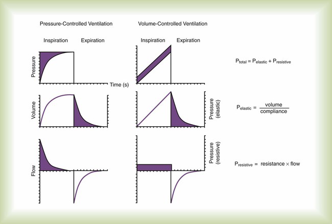
Figure 42-2 shows that the expiratory lung pressure curves are the same shape for both volume and pressure control. This shape is called an exponential decay waveform (often called a decelerating waveform), and it is characteristic of passive emptying of the lungs (exhalation). Solving the equation of motion for lung pressure (assuming no auto-PEEP) provides the following expression:
 Equation 42-2
 Equation 42-3
This expression shows that after an expiratory time equal to one time constant, only 37% of the lung pressure is left. Because volume is equal to pressure multiplied by compliance, multiplication of both sides of Equation 42-3 by compliance shows that only 37% of the tidal volume remains in the lungs. The implication is that 63% of the tidal volume has been exhaled. After two time constants (i.e., t = 2RC), exhalation is 86% completed, and after three time constants, exhalation is 95% complete. After five time constants, exhalation is considered to be 100% complete for practical purposes (Figure 42-3).
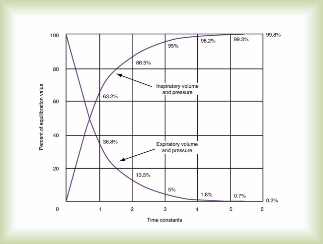
A similar expression can be derived for passive inhalation:
 Equation 42-4
When this equation is graphed, it looks like the curved line showing lung pressure and volume during inhalation for pressure-controlled ventilation in Figure 42-2. These same equations govern the passive flow curves for volume-controlled and pressure-controlled ventilation. It is important to understand the concept of time constants to make appropriate ventilator setting adjustments. In any mode of ventilation, the expiratory time should be at least three time constants long to avoid clinically important gas trapping. Similarly, in pressure-controlled modes, inspiratory time (for passive inspiration) should be at least five time constants long to get the maximum tidal volume from the set pressure gradient (i.e., peak inspiratory pressure [PIP] − end expiratory pressure).
Control Circuit
Mechanical control circuits use devices such as levers, pulleys, and cams. These types of circuits were used in the early manually operated ventilators illustrated in history books.8 Pneumatic control is provided using gas-powered pressure regulators, needle valves, jet entrainment devices, and balloon-valves. Some transport ventilators use pneumatic control systems.
Fluidic logic-controlled ventilators, such as the Bio-Med MVP-10 (Bio-Med Devices, Stanford, Connecticut) and Sechrist IV-100B (Sechrist, Anaheim, California), also use pressurized gas to regulate the parameters of ventilation. However, instead of simple pressurized valves and timers, these ventilators use fluidic logic circuits that function similar to electrical circuit boards.9 Fluidic control mechanisms have no moving parts. In addition, fluidic circuits are immune to failure from surrounding electromagnetic interference, as can occur around MRI equipment.
Control Variables
A control variable is the primary variable that the ventilator manipulates to cause inspiration. There are only three explicit variables in the equation of motion that a ventilator can control: pressure, volume, and flow. Because only one of these variables can be the independent variable, the others are dependent variables. In other words, only one variable can be directly controlled at a time, and a ventilator must function as a pressure, volume, or flow controller. Time is implicit in the equation of motion and in some cases serves as a control variable. Figure 42-4 illustrates the criteria for determining what variable the ventilator controls at any given time.
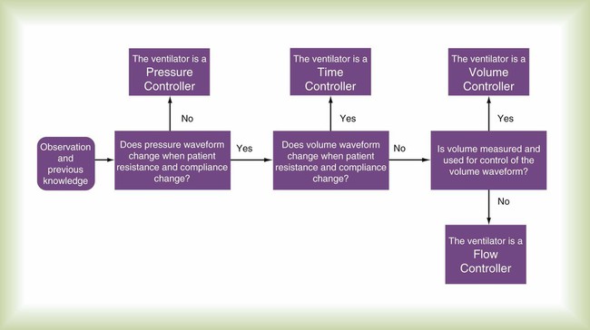
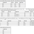
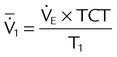
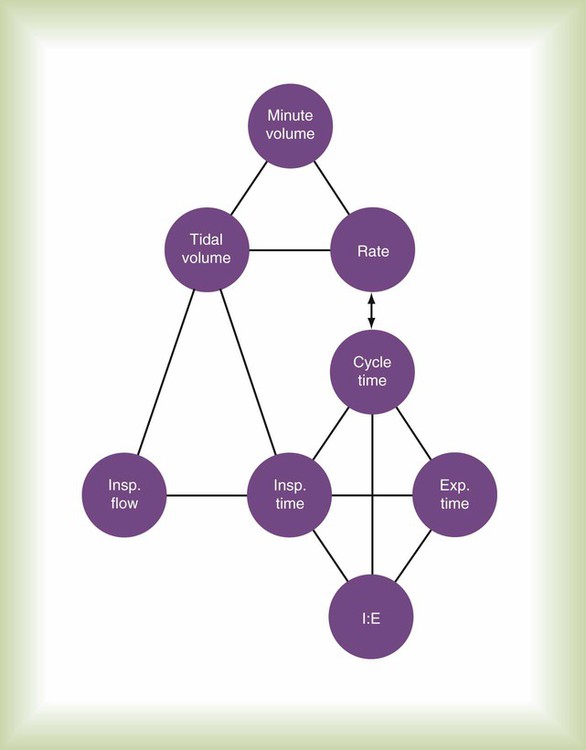
Figure 42-5 illustrates the important variables for volume-controlled modes. It shows that the primary variable we wish to control is the patient’s minute ventilation. A particular ventilator may allow the operator to set minute ventilation directly. More frequently, minute ventilation is adjusted by means of a set tidal volume and frequency. Tidal volume is a function of the set inspiratory flow and the set inspiratory time. Inspiratory time is affected by the set frequency and, if applicable, the set inspiratory-to-expiratory (I : E) ratio. The mathematical relationships among all these variables are shown in Table 42-1.
TABLE 42-1
| Mode | Parameter | Symbol | Equation |
| Volume-controlled | Tidal volume (L) | VT |  |
 |
|||
| Mean inspiratory flow (L/min) |  |
 |
|
 |
|||
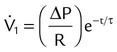
| Pressure-controlled | Tidal volume (L) | VT | VT = ΔP × C × (1 − e−t/τ) |
| Instantaneous inspiratory flow (L/min) |  |
 |
|
| Pressure gradient (cm H2O) | ΔP | ΔP = PIP − PEEP | |
| Both modes | Exhaled minute ventilation (L/min) |  |
 |
| Total cycle time or ventilatory period (seconds) | TCT | TCT = TI + TE = 60 ÷ f | |
| I : E ratio | I : E | 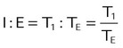 |
|
| Time constant (seconds) | τ | τ = R × C | |
| Resistance (cm H2O/L/sec) | R |  |
|
| Compliance (L/cm H2O) | C |  |
|
| Elastance | E |  |
|
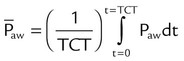
| Mean airway pressure (cm H2O) |  |
 |
|
| Primary variables | Pressure (cm H2O) | P | |
| Volume (L) | V | ||
| Flow (cm H2O/L/sec) |  |
||
| Time (sec) | τ | ||
| Inspiratory time (sec) | TI | ||
| Expiratory time (sec) | TE | ||
| Frequency (breaths/min) | f | ||
| Base of natural logarithm (≈2.72) | e |
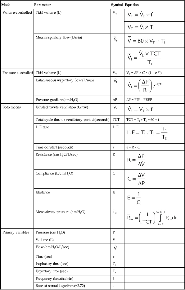
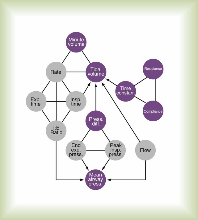
With pressure-controlled modes, the goal is also to maintain adequate minute ventilation. However (as the equation of motion shows), when pressure is controlled, tidal volume and minute ventilation are determined not only by the ventilator’s pressure settings but also by the elastance and resistance of the patient’s respiratory system. This additional variable makes minute ventilation (and gas exchange) less stable in pressure-controlled modes than in volume-controlled modes. Figure 42-6 shows the important variables for pressure-controlled modes. Tidal volume is not set on the ventilator. It is the result of the pressure settings and the patient’s lung mechanics and the inspiratory time. On some ventilators, the speed with which the PIP is achieved (i.e., the pressure rise time) is adjustable. That adjustment affects the shape of the pressure waveform and the mean airway pressure. Mean airway pressure is important because, within reasonable limits, as the mean airway pressure increases, arterial O2 tension increases. Mean airway pressure is higher for pressure-controlled modes than for volume-controlled modes (at the same tidal volume) owing to the differences in the shapes of the airway pressure waveforms.
Phase Variables
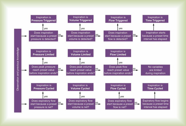
The phase variable is a variable that is measured and used by the ventilator to initiate some phase of the breath cycle. The variable causing a breath to begin is the trigger variable. The variable limiting the magnitude of any parameter during inspiration is the target variable. The variable causing a breath to end is the cycle variable. To describe what happens during expiration, the baseline variable that is in effect must be known. Figure 42-7 shows the criteria for determining phase variables.
Trigger Variable
Flow Triggering
Flow Trigger Variable
Compared with pressure, using flow as the trigger variable decreases a patient’s work of breathing.11,12 However, ventilators that use a flow-triggering mechanism tend to be highly susceptible to circuit leaks or movement caused by turbulence or gas flow through condensed water. Either of these conditions can cause spurious breaths, which can disrupt patient-ventilatory synchrony and increase the work of breathing. The perception exists, with regard to the most recent generation of ICU ventilators, that pressure and flow triggering are equally effective. Using volume as the trigger can help overcome synchrony problems caused by circuit leaks, but at the present time only the Draeger Babylog (Draeger Medical, Telford, Pennsylvania) uses true volume triggering.
Other Trigger Variables
Mini Clini
Calculate the Expiratory Time Setting from the Frequency and Inspiratory Time
 Problem

Target Variable
Clinicians often confuse target variables with cycle variables. A cycle variable always ends inspiration. A target variable does not terminate inspiration—it sets an upper bound only for pressure, volume, or flow. Figure 42-8 illustrates the importance of distinguishing between target and cycle variables.
Cycle Variable
Flow Cycling
When a ventilator is set to flow cycle, it delivers flow until a preset level is met, and then flow stops and expiration begins. The most frequent application of flow cycling is in the pressure support mode. In this mode, the control variable is pressure, and the ventilator provides the flow necessary to meet the inspiratory pressure limit. In doing so, flow starts out at a relatively high value and decays exponentially (see Figure 42-2). When flow has decreased to a relatively low value (e.g., 25% of peak flow, preset by the manufacturer), inspiration is cycled off. Manufacturers often set the cycle threshold slightly above zero flow to avoid inspiratory times from getting so long that patient synchrony is degraded.
Time Cycling
Mini Clini
Calculate Inspiratory Hold Time Given Set Inspiratory Time, Tidal Volume, and Flow When Using the Siemens Servo
 Problem
1. Calculate the inspiratory flow time (TIF) using appropriate unit conversions:
2. Compare the set inspiratory time (0.8 second) with the flow time resulting from the tidal volume and flow settings (0.5 second). Inspiratory time lasts longer than inspiratory flow. Because inspiration is time cycled, this means that there is an inspiratory hold of duration equal to 0.8 − 0.5 = 0.3 second.
3. You could eliminate the inspiratory hold either by decreasing the inspiratory flow or by decreasing the inspiratory time. The goal is to minimize the mean inspiratory pressure. You choose to decrease inspiratory time for two reasons: (1) It decreases the I : E ratio and may allow more time for spontaneous breaths to occur, lowering mean intrathoracic pressure; (2) decreasing inspiratory flow may make tidal volume delivery slower than the patient demands, decreasing patient-ventilator synchrony.

 ) and two parameters (E and R). The ventilator can be triggered or cycled by a signal representing Pmus (e.g., the electrical signal of the diaphragm as with neurally adjusted ventilatory assist or a calculated estimate of Pmus) or the volume or flow generated by the patient’s ventilatory muscles (Vmus and
  [e.g., volume triggering in the Draeger Babylog or flow triggering on many other ventilators]). The ventilator can be triggered or cycled by the patient’s passive respiratory system mechanics (E and R). Examples are flow triggering with the AutoRelease feature on the Draeger Evita Infinity V500 ventilator and flow cycling during pressure support on any ventilator. Manufacturers may have specific marketing terms for flow cycling. For example, flow cycling on the Puritan Bennett 840 ventilator (Pleasanton, California) is termed E-sensitivity. Given the definition of patient trigger and cycle signals, we can define machine trigger and cycle signals as being anything else that starts or ends inspiration (excluding operator-generated manual signals).
Modes of Ventilation
• Control variable (pressure or volume)
• Breath sequence (pattern of mandatory or spontaneous breaths, or both)
An example of how this mode classification system can be applied is shown in Table 42-2. The key to understanding modes of ventilation is to link simple, defined terms in a way that allows descriptions of varying complexity to be built; this is much more practical than trying to memorize arbitrary names for every new feature a manufacturer wishes to promote. It is analogous to using an alphabet of several dozen letters to build words rather than memorizing tens of thousands of separate ideographs that each represents a word. One need only compare the English written language with the Chinese written language to appreciate the analogy.3
TABLE 42-2
Specifications for Some Modes Found on the Draeger Evita XL Ventilator
| Draeger Mode Name | Breathing Pattern | Mandatory Breaths* | Spontaneous Breaths | ||||||
| Targeting Scheme | Trigger† | Target‡ | Cycle | Targeting Scheme | Trigger | Target | Cycle | ||
| CMV | VC-CMV | Set-point | T | F, V | T | NA | NA | NA | NA |
| Operational Logic: Every breath is volume controlled and mandatory. Every breath is machine triggered and cycled | |||||||||
| CMV + AutoFlow | PC-CMV | Adaptive | T, F | P | T | NA | NA | NA | NA |
| Operational Logic: Mandatory breaths are pressure controlled, but patient may trigger breath. If target tidal volume is not met, pressure target is automatically adjusted | |||||||||
| CMV + Pressure Limited Ventilation | PC-CMV | Dual | T, F | F, V, P | T | NA | NA | NA | NA |
| Operational Logic: Mandatory breath starts out in volume control but switches to pressure control if airway pressure reaches set Pmax | |||||||||
| SIMV | VC-IMV | Set-point | T, F | F, V | T | Set-point | P | P | P |
| Operational Logic: Mandatory breaths are volume-controlled. Spontaneous breaths may occur within window determined by set rate and are not assisted (i.e., inspiratory pressure stays at baseline) | |||||||||
| PC+ | PC-IMV | Set-point | T, F | P | T | Set-point | F | P | F |
| Operational Logic: Mandatory breaths are pressure-controlled. Spontaneous breaths may occur within window determined by set rate and are not assisted (i.e., inspiratory pressure stays at baseline) | |||||||||
| SIMV + AutoFlow | PC-IMV | Adaptive | T, F | P | T | Set-point | P | P | P |
| Operational Logic: Mandatory breaths are pressure-controlled and pressure target is automatically adjusted if target tidal volume is not met. Spontaneous breaths may occur with window determined by set rate and are not assisted (i.e., inspiratory pressure stays at baseline) | |||||||||
| CPAP | PC-CSV | NA | NA | NA | NA | Set-point | P | P | P |
| Operational Logic: Spontaneous breaths are unassisted | |||||||||
| Pressure Support | PC-CSV | NA | NA | NA | NA | Set-point | F | P | F |
| Operational Logic: Spontaneous breaths are assisted (i.e., inspiratory pressure increases above baseline) | |||||||||
| SmartCare | PC-CSV | NA | NA | NA | NA | Intelligent | F | P | F |
| Operational Logic: Spontaneous breaths are assisted (i.e., inspiratory pressure increases above baseline). Pressure support level automatically adjusted by rule-based expert system | |||||||||
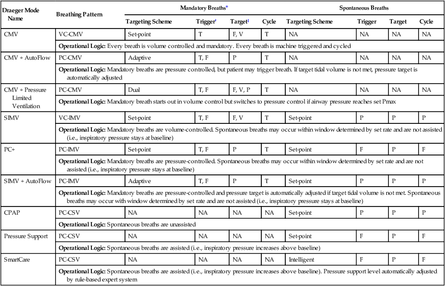
*Patient can take spontaneous breaths during mandatory breaths with PC and AutoFlow but not with Pressure Limited Ventilation.
†Flow trigger may be turned off. When off, mandatory breaths cannot be triggered, but spontaneous breaths are automatically pressure triggered with factory set sensitivity.
‡Volume target achieved if inspiratory time set longer than tidal volume/flow.
Control Variable
There are clinical advantages and disadvantages to volume versus pressure control, which are discussed in Chapter 43. Briefly, volume control results in a more stable minute ventilation (and more stable blood gases) than pressure control if lung mechanics are unstable. Pressure control allows better patient-ventilatory synchrony with the patient because inspiratory flow is not constrained to a preset value. Although it is possible to control only one variable at a time, a ventilator can automatically switch between pressure control and volume control in an attempt to guarantee minute ventilation while maximizing patient synchrony. This feature is called dual control13 and is discussed in the section on Targeting Schemes.
Volume Control
Infant ventilators, such as the Sechrist, are the simplest examples of flow controllers. In this ventilator, flow is controlled directly by a flowmeter and an exhalation valve. As long as the airway pressure does not reach the set pressure limit, the resulting volume waveform remains constant.10 Current-generation adult ICU ventilators typically function as flow controllers. However, these systems are much more complex than ventilators such as the Sechrist; flow is measured and adjusted hundreds of times per second through sophisticated computerized output control valves.
 Rule of Thumb
Breath Sequence
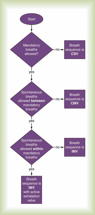
The classification of modes requires the definition of two basic categories of breaths: spontaneous and mandatory. A spontaneous breath is a breath for which the start and end of inspiration may be determined by the patient, independent of any machine settings for inspiratory time and expiratory time. In other words, the patient both triggers and cycles the breath. As a consequence, the patient retains substantial, if not complete, control over the timing (frequency and inspiratory time) and size (tidal volume) of the breath. A spontaneous breath may occur during a mandatory breath (Figure 42-9). A spontaneous breath may be assisted or unassisted. An assisted breath is a breath during which all or part of inspiratory or expiratory flow is generated by a change in transrespiratory pressure (i.e., airway pressure minus body surface pressure) owing to an external agent (e.g., manual or automatic resuscitator, mechanical ventilator).
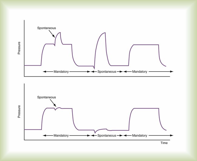
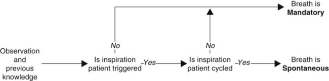
A mandatory breath is a breath for which the start or end of inspiration (or both) is determined by the ventilator, independent of the patient; the machine triggers or cycles the breath. As a consequence, the patient substantially, if not completely, loses control over the timing (frequency and inspiratory time) and size (tidal volume) of the breath. Mandatory breaths are generally assisted. Box 42-1 shows an algorithm defining spontaneous and mandatory breaths.
The key difference now between CMV and IMV is that with CMV, the clinical intent is to make every inspiration a mandatory breath, whereas with IMV, the clinical intent is to partition ventilatory support between mandatory and spontaneous breaths. This means that during CMV, if the operator decreases the ventilatory rate (often considered to be a safety “backup” rate in the event of apnea), the level of ventilatory support is unaffected, provided that the patient continues triggering mandatory breaths at the same rate (i.e., each breath is assisted to the same degree). With IMV, the rate setting directly affects the number of mandatory breaths and the level of ventilatory support (assuming that spontaneous breaths are not assisted to the same degree as mandatory breaths). CMV is normally considered a method of “full” ventilatory support, whereas IMV is usually viewed as a method of partial ventilatory support. For classification purposes, if spontaneous breaths are not allowed between mandatory breaths, the breath sequence is CMV; otherwise, the sequence is IMV (Figure 42-10). Given that almost every ventilator has a mechanism to synchronize breath delivery with patient effort, it is no longer necessary to add an S to designate synchronized IMV (SIMV). The term SIMV was important in the early days of mechanical ventilation but is an anachronism now. Patient triggering can be specified in the description of mode phase variables.
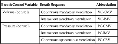
When a breath sequence is added to the control variable in classifying a mode, the result is a breathing pattern. A breathing pattern provides a greater ability to discriminate between similar modes. For example, it is possible to distinguish between pressure-control IMV (PC-IMV) and pressure-control CSV (PC-CSV). By classifying modes based solely on the breathing pattern, there are only five possibilities in two groups (Table 42-3). The utility of this system is immediately obvious. A new mode, such as airway pressure release ventilation (APRV), can be explained as simply a form of PC-IMV. Assuming the clinician already understands the concept of PC-IMV, it takes little effort to understand the additional nuances of APRV (e.g., different labels for control settings, alarms). This level of description avoids the cumbersome verbal ad hoc definition for APRV, such as “a mode that allows spontaneously breathing patients to breathe at a positive-pressure level but drops briefly to a reduced pressure level for carbon dioxide (CO2) elimination during each breathing cycle,” or the misleading description of some authors who explain APRV as two levels of continuous positive airway pressure.
TABLE 42-3
All Modes of Ventilation Can Be Characterized by One of Five Breathing Patterns
| Breath Control Variable | Breath Sequence | Abbreviation |
| Volume (control) | Continuous mandatory ventilation | VC-CMV |
| Intermittent mandatory ventilation | VC-IMV | |
| Pressure (control) | Continuous mandatory ventilation | PC-CMV |
| Intermittent mandatory ventilation | PC-IMV | |
| Continuous spontaneous ventilation | PC-CSV |
Targeting Schemes
Control variables and the differences between pressure and volume control have been discussed, but what is meant by control has not been explained. There are two general ways to control a variable: open loop control and closed loop control.14
Closed Loop Control
The basic concept of closed loop control has evolved into at least six different ventilator control systems or targeting schemes14 (set-point, dual, servo, adaptive, optimal, and intelligent). These targeting schemes are the foundation that makes possible several dozen apparently different modes of ventilation. Once it is understood how these targeting schemes work, many of the apparent differences are seen to be similarities. A lot of the confusion surrounding ventilator marketing hype is avoided, and the true clinical capabilities of different ventilators are appreciated.
Servo
Set-point targeting attempts to maintain a constant output to match a constant input, whereas servo targeting is designed to track a moving input, similar to power steering on an automobile. Servo targeting was developed during World War II to aim ships’ guns and radar equipment. It makes the proportional assist mode possible.15 In this mode, the output of the ventilator follows and amplifies the patient’s own flow pattern. The ventilator can support the abnormal load imposed by disease, while the patient’s own muscles handle a normal load secondary to the respiratory system’s natural resistance and compliance.
Optimal
Other forms of optimal control give the ventilator even more authority using exhaled CO2 as a feedback signal.16 In Europe, Hamilton Medical has introduced IntelliVent, a system for complete closed loop control of minute ventilation, fractional inspired oxygen (FiO2), and PEEP using both CO2 and SpO2 as feedback signals.
Intelligent
The term intelligent refers to automatic targeting strategies that make use of artificial intelligence methods, such as “fuzzy logic,” rule-based expert systems, and even neural networks.14 This type of automatic targeting is yet another evolutionary step because it gives the ventilator more information than what may be contained in a simple, static, mathematical model. Knowledge-based targeting schemes attempt to capture the experience of human experts and expand the scope of control to potentially all parameters of the ventilatory mode. An experimental application of this type of control has been described for automatic adjustment of pressure support.17 That system has now been commercialized as the Draeger SmartCare mode.
An even more sophisticated approach coupled a knowledge base with fuzzy logic.18 In this case, the ventilator used both instantaneous measurements of physiologic values such as respiratory rate and saturation and their rates of change. Fuzzy logic19 was used as a way to integrate the measurements with predefined ranges of values representing the patient status. When the patient’s status was determined, appropriate expert rules were selected from a lookup table and used to adjust the ventilator. Although this was a limited application, it proved the concept.
The most convincing proof of concept was presented by East and colleagues.20 These investigators used a rule-based expert system for ventilator management in a large, multicenter prospective randomized trial. Although survival and length of stay were not different between human and computer management, computer control resulted in a significant reduction in multiorgan dysfunction and lower incidence and severity of lung overdistention injury. However, the most important finding was that expert knowledge can be encoded and successfully shared with institutions that had no input into the model. The expert system did not directly control the ventilator but rather made suggestions for the human operator. Theoretically, the operator could be eliminated.
Perhaps the most exotic targeting scheme to date is the artificial neural network.21 This experimental system (not yet commercially available) did not directly control the ventilator but acted as a decision support system. Snowden and coworkers21 commented that the neural network was capable of learning, which offers significant advantages over static rule-based systems.
Neural networks are essentially data modeling tools used to capture and represent complex input-output relationships. A neural network learns by experience the same way a human brain does, by storing knowledge in the strengths of internode connections. As data modeling tools, neural networks have been used in many business and medical applications for both diagnosis and forecasting.22 A neural network, similar to an animal brain, is composed of individual neurons. Signals (action potentials) appear at the unit’s inputs (synapses). The effect that each signal has may be approximated by multiplying the signal by some number or weight to indicate the strength of the synapse. The weighted signals are summed to produce overall unit activation. If this activation exceeds a certain threshold, the unit produces an output response. As the network learns, the weights change, affecting the final output.
At the highest level of detail, a mode can be fully characterized by adding the phase variables, followed by detailing the operational logic programmed into the software control system. The specification of the breathing pattern that the mode can produce, the type of targeting, and the specific strategy (phase variable and operational logic) it uses for both mandatory and spontaneous breaths make up a complete classification for any mode of ventilation (see Table 42-2).
1. Mandatory breaths are volume-controlled with set-point targeting, and spontaneous breaths are pressure-controlled with adaptive targeting (i.e., volume support).
2. Mandatory breaths are pressure-controlled with set-point targeting, and spontaneous breaths are pressure-controlled with set-point targeting (i.e., pressure support).
3. Mandatory breaths are pressure-controlled with adaptive targeting (e.g., pressure-regulated volume control), and spontaneous breaths are pressure-controlled with adaptive targeting (i.e., volume support).
Output Waveforms
Electrocardiograms and blood pressure waveforms are studied to understand heart physiology. In the same way, to understand ventilator-patient interaction, output waveforms must be examined. The output waveforms of interest during ventilatory support are pressure, volume, and flow. For each control variable, current ventilators produce a limited number of waveforms. Basic waveforms are shown in Figure 42-11.
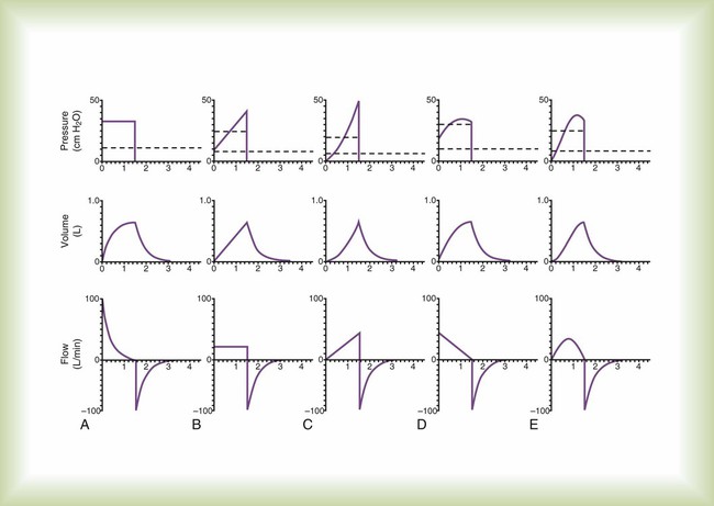
Because the waveforms in Figure 42-11 are models, they do not show the minor deviations, or “noise,” often seen during actual ventilator use. Such noise can be caused by many factors, including vibration and turbulence. These waveforms also do not show the effect of expiratory circuit resistance because this varies depending on the ventilator and type of circuit. The waveforms do not show the various indicators of problems with ventilator-patient synchrony (e.g., improper sensitivity setting and gas trapping), which are beyond the scope of this chapter. Finally, waveform appearances change when the time scale is altered. A faster sweep (shorter time scale) tends to widen a given waveform, whereas a slower sweep speed (longer time scale) compresses the waveform.
Pressure
Rectangular
Mathematically, a rectangular waveform is referred to as a step or instantaneous change in transrespiratory pressure from one value to another (see Figure 42-11, A). In response, volume increases exponentially from zero to a steady-state value equal to compliance multiplied by the change in airway pressure (i.e., PIP − PEEP). Inspiratory flow decreases exponentially from a peak value (at the start of inspiration) equal to (PIP − PEEP) divided by resistance.
Exponential
Exponential pressure waveforms are common outputs of neonatal ventilators and can be produced by adjusting the pressure rise control on some newer adult ventilators. The resulting pressure and volume waveforms can take on various shapes ranging from an exponential rise (same shape as the volume waveform in Figure 42-11, A) to a linear rise (same shape as the volume waveform in Figure 42-11, B). Generally, the flow waveform is similar to that seen in Figure 42-11, A except that peak inspiratory flow is reached gradually rather than instantaneously (resulting in a rounded rather than peaked waveform), and peak flow is lower than with a rectangular pressure waveform.
Sinusoidal
As previously described, a sinusoidal pressure waveform can be created by attaching a piston to a rotating crank. In addition, a linear drive motor driven by a microprocessor can produce a sine wave pressure pattern. In response, the volume and flow waveforms are also sinusoidal, but they attain their peak values at different times (see Figure 42-11, E).
Volume
Ramp
Volume controllers that produce an ascending ramp waveform (i.e., the Bennett MA-1) produce a linear rise in volume from zero at the start of inspiration to the peak value, or set tidal volume, at end-inspiration (see Figure 42-11, B). In response, the flow waveform is rectangular. The pressure waveform rises instantaneously from zero to a value equal to resistance multiplied by flow at the start of inspiration. From here, it rises linearly to its peak value (PIP) equal to elastance multiplied by tidal volume plus resistance multiplied by flow.
Sinusoidal
This volume waveform is most often produced by ventilators whose drive mechanism is a piston attached to a rotating crank (e.g., Emerson). The output waveform of this type of ventilator can be approximated by the first half of a cosine curve, whose shape in this case is referred to as a sigmoidal curve (see Figure 42-11, E). Because volume is sinusoidal during inspiration, pressure and flow are also sinusoidal.
Flow
Rectangular
A rectangular flow waveform is perhaps the most common output (see Figure 42-11, B). When the flow waveform is rectangular, volume is a ramp waveform, and pressure is a step followed by a ramp as described for the ramp volume waveform.
Ramp
Ascending Ramp
A true ascending ramp waveform starts at zero and increases linearly to the peak value (see Figure 42-11, C). Actual ventilator flow waveforms may be truncated; inspiration starts with an initial instantaneous flow. The Bear-5 starts inspiration at 50% of the set peak flow. Flow increases linearly to the set peak flow rate. In response to an ascending ramp flow waveform, the pressure and volume waveforms are exponential with a concave upward shape. As previously described with the 8400 St and STi ventilators, this particular ventilator may still be in use, however, the current manufacturer does not actively produce or support this product.
Descending Ramp
A true descending ramp waveform starts at the peak value and decreases linearly to zero (see Figure 42-11, D). Ventilator flow waveforms are usually truncated; inspiratory flow rate decreases linearly from the set peak flow until it reaches some arbitrary threshold where flow drops immediately to zero (e.g., the Puritan Bennett 7200a ends inspiration when the flow rate decreases to 5 L/min). In response to a descending ramp flow waveform, the pressure and volume waveforms are exponential with a concave downward shape.
Sinusoidal
Some ventilators offer a mode in which the inspiratory flow waveform approximates the shape of the first half of a sine wave (see Figure 42-11, E). As with the ramp waveform, ventilators often truncate the sine waveform by starting and ending flow at some percentage of the set peak flow rather than start and end at zero flow. In response to a sinusoidal flow waveform, the pressure and volume waveforms are also sinusoidal but out of phase with each other.

Operator Interface
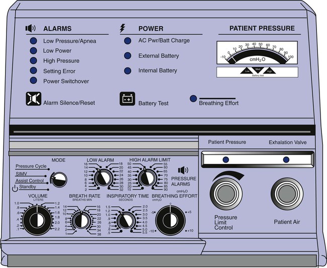
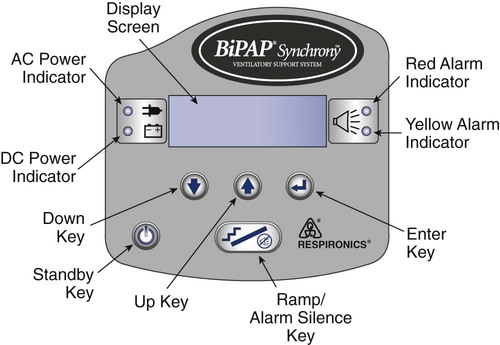
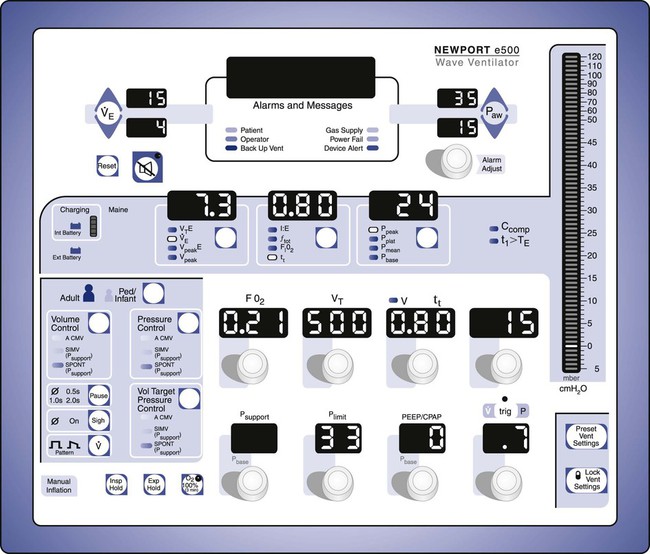
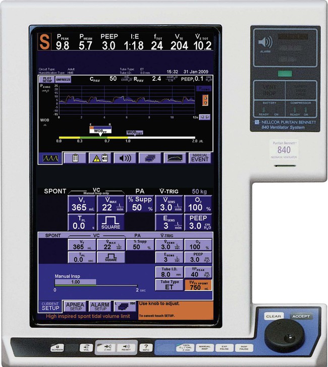
The ventilator’s operator interface, or ventilator display, has undergone extensive evolution over the last 30 years. Originally, the displays on ventilators were “analog.” Operator inputs, or settings, were accomplished with hard-wired knobs, buttons, and dials. The ventilator outputs, such as alarm conditions and ventilating pressure, were displayed with bulbs, light emitting diodes (LEDs), and meters. Some older home care ventilators still use analog displays (Figure 42-12). The development of inexpensive microprocessors has led manufacturers to use “digital” displays almost exclusively on all types of ventilators. Digital interfaces use LED or LCD screens for visual display of ventilator data along with some multipurpose hard-wired buttons. The simplest example would be the display of a bilevel positive airway pressure machine used for treating sleep apnea at home (Figure 42-13). A more advanced digital display uses dedicated special-purpose buttons and dials (Figure 42-14). The most advanced interfaces use the concept of the “virtual” instrument, meaning that knobs, buttons, dials, and meters are simulated on a computer screen (sometimes a touch screen) and often incorporating a single mechanical dial that is used to set multiple parameters (Figure 42-15). Computer screens allow graphic displays of alarm settings as bar graphs along with pressure, volume, and flow waveforms as scalars or loops.
Operator Inputs
Mode Settings
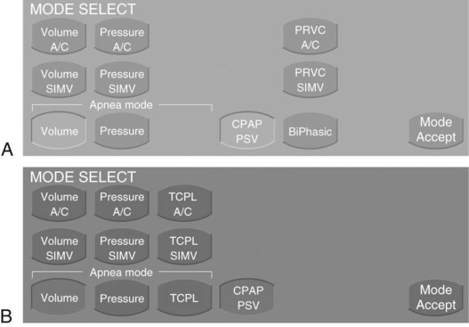
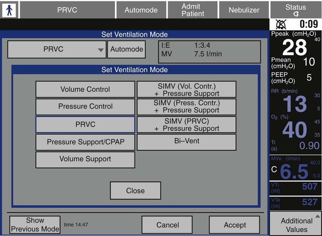
There is no standardization among ventilator manufacturers regarding the names of modes, their classification, or how the operator identifies and sets them on a given device. This requires the operator to learn the specific terminology and layout of each individual brand of ventilator for every function it provides. For clinical settings where many different ventilator brands are used, this can be a daunting and perhaps unachievable task. For an example of how different and confusing ventilator displays can be regarding mode selection, compare Figures 42-16 and 42-17.
Trigger, Target, and Cycle Variable Settings
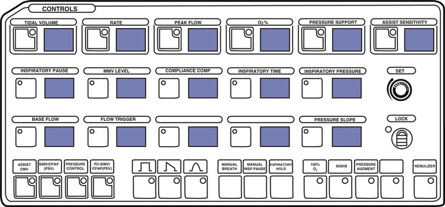
There was a time when all the input settings and output displays of a modern ICU ventilator could fit on the face of the ventilator, even in digital format (Figure 42-18). However, with the proliferation of computer screens for displays and the increasing complexity of modes, the user is now often faced with the need to switch between multiple screens to access all of the ventilator’s capabilities (Figure 42-19). This is a relatively new challenge for the ventilator industry, and more work needs to be done to perfect the operator interface. More recent research on the topic suggests that the design of the user interface is relevant to the occurrence of operational failures and that ventilator designers could optimize the user-interface design to reduce operational failures.23
Target variables for pressure control include inspiratory pressure and sometimes pressure rise time. The latter variable sets the speed with which inspiratory pressure increases to the target value and controls peak inspiratory flow. Inspiratory pressure is another term that causes confusion because of nonstandard usage. On some ventilators, it is measured relative to atmospheric pressure (and should be called peak inspiratory pressure), and on others it is measured relative to PEEP and should be called simply inspiratory pressure.24 The problem is that when a patient is changed from one ventilator (or mode) using one convention to another ventilator (or mode) with the other convention, the risk of inadvertently setting the wrong inspiratory pressure increases and could lead to adverse events.
Alarm Settings
The purpose of ventilator alarms is to bring events to the attention of the clinician. Events are conditions or occurrences that require clinician awareness or intervention. Events can be classified according to four levels of priority.25 Level 1 events are immediately life-threatening. These include insufficient or excessive gas delivery to the patient, exhalation valve failure, control circuit failure, or loss of power. Alarm indicators in this category should be mandatory (cannot be turned off by the operator), redundant, and noncanceling. Level 2 events range from mild irregularities in machine function to dangerous situations that could threaten patient safety if left unattended. These include failure of the air-O2 blending system, inadequate or excessive PEEP, autotriggering, circuit leak, circuit occlusion, inappropriate I : E ratio, and failure of the humidification system. Alarms in this category are not redundant and may be self-canceling (i.e., automatically turned off if the event ceases). Level 3 events reflect changes in the level of ventilatory support. Examples include changes in the patient’s ventilatory drive or respiratory system mechanics and the presence of auto-PEEP. Level 3 events often trigger the same alarms as levels 1 and 2. Level 4 events are focused entirely on the patient. These include changes in gas exchange, dead space, oxygenation, and cardiovascular functions. Many ventilators do not warn of these events, and external monitors are required for surveillance.
Ventilators do not display alarm settings in terms of levels of priority. Instead, they tend to lump them all together on the screen (Figures 42-20 and 42-21; see Figure 42-15). The setting of alarm thresholds is a complicated topic that has been studied but for which little information is available regarding mechanical ventilation. The basic problem is to maximize true alarms and minimize false alarms. A high false alarm rate leads to habituation and clinicians ignoring warnings. False alarms can also lead to inappropriate responses. In one 200-hour study of an ICU, 1214 alarms occurred, and 2344 tasks were performed. On average, alarms occurred six times per hour; 23% were effective, 36% were ineffective, and 41% were ignored.26 In another ICU study, during 982 hours of observation, 5934 alarms occurred, corresponding to six per hour. About 40% of the alarms did not correctly describe the patient condition and were classified as technically false; 68% of those were caused by manipulation. Only 885 (15%) of all alarms were considered clinically relevant.27
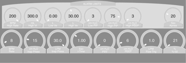
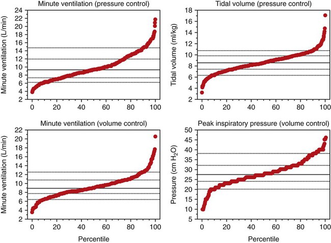
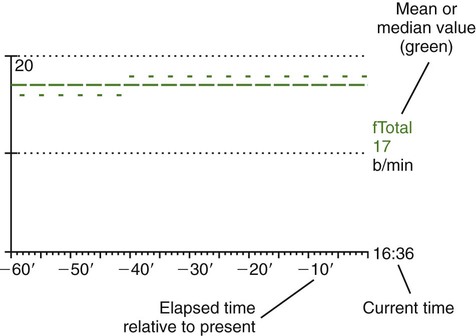
Although these studies did not address mechanical ventilator alarms specifically, it is not hard to imagine similar results for such a study. Ventilator alarms are usually set by the operator (or as default values by the ventilator) as either a set value or a set percentage of the current value. Examples would be low and peak airway pressure alarms set at the current value ±5 cm H2O or low and peak tidal volume and minute ventilation set at ±25% of the current value.25 The problem is that the parameters we want to set alarms for, in particular, airway pressure, tidal volume, and minute ventilation, are highly variable, with significant portions at extreme values (Figure 42-22).28 Limits set as absolute values or percentages may reduce safety for some extreme values, while increasing nuisance events for other values. An alternative approach might be to reference the alarm limits to the current value of the parameter such that extreme values have tighter limits. Further research is needed to identify optimization algorithms (i.e., minimize both harmful and nuisance events) for intelligent targeting schemes to set alarms automatically during mechanical ventilation.
Ventilator Output Displays
Waveforms and Loops
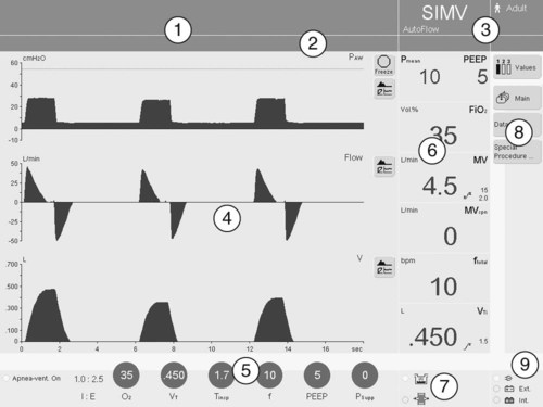
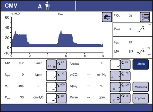
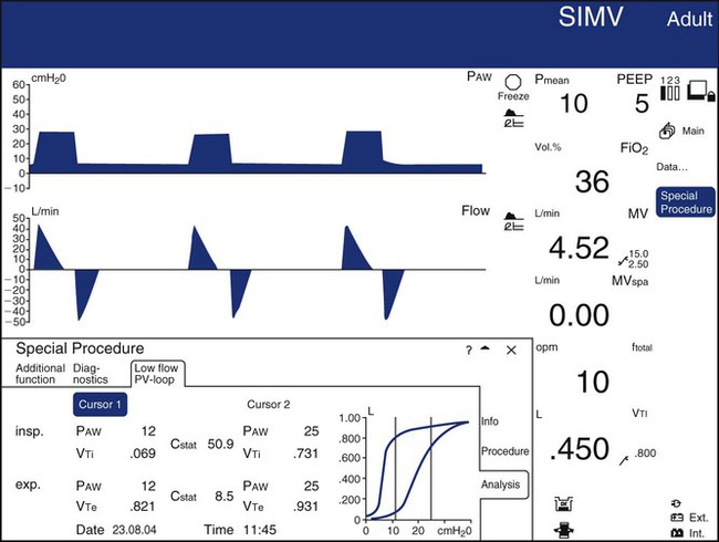
Most ICU ventilators display waveforms (sometimes called scalars) of airway pressure, volume, and flow as functions of time. Such displays are useful for identifying the effects of changes in settings or mechanics on the level of ventilation. They are also very useful for identifying sources of patient-ventilator asynchrony, such as missed triggers, flow asynchrony, and delayed or premature cycling.29 They can also display one variable against another as an x-y or “loop” display. The most common loop displays show pressure on the horizontal axis and volume on the vertical axis or volume on the horizontal axis and flow on the vertical axis. Pressure-volume loop displays are useful for identifying optimal PEEP levels (quasistatic loops only) and overdistention. Flow-volume loops are useful for identifying the response to bronchodilators. An example of a composite display showing numeric values, waveforms, and loops is shown in Figure 42-23.
Picture Graphics
A new development in ventilator displays involves the use of picture graphics to represent useful information about the patient-ventilator system. A study30 showed that subjects with graphic rather than conventional displays of obstructed endotracheal tubes and auto-PEEP problems were detected and treated faster. The investigators also reported significantly lower subjective workloads using the graphic display.
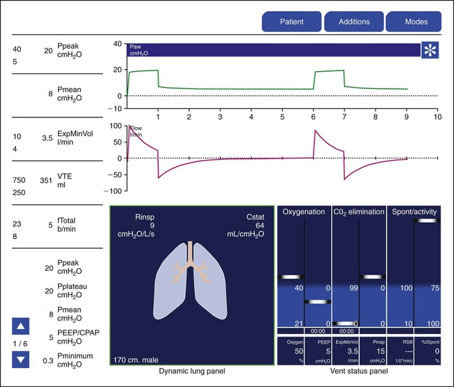
Hamilton Medical was the first manufacturer to use innovative picture graphics on their G5 ventilator. In particular, they created a graphic representation of the lungs, called a dynamic lung panel, which visually displayed information about resistance and compliance by the shape and color of the lungs and airways (Figure 42-25). In addition, Hamilton Medial created a unique graphic representation called the vent status panel that displays key parameters (e.g., oxygenation, ventilation, and spontaneous breathing activity) and shows when each item is in or out of an acceptable zone and for how long. This graphic display makes weaning status easy to identify. Draeger Medical followed with a similar graphic display called Smart Pulmonary View, which is a graphic display of respiratory system compliance and resistance and of the spontaneous and mandatory minute volume (Figure 42-26).

Types of Ventilators
Critical Care Ventilators
High-Frequency Ventilators
High-frequency jet ventilators require a high pressure source (20 to 50 psig) to function. This type of ventilator consists of a system for regulating inlet pressure (psig) and a cycling mechanism and a device such as an air-O2 blender for controlling FiO2. The small volumes of gas are delivered at rapid rates (4 to 250 times the normal respiratory rate).31 The benefits of rescue and elective use of high-frequency jet ventilation as a treatment for acute lung disease and acute respiratory distress syndrome (ARDS) are unclear.31 However, the literature supports its effectiveness in maintaining alveolar ventilation and reducing morbidity during surgical repair of tracheal and airway anomalies.32,33
High-frequency oscillation also allows very small tidal volumes to be delivered at rapid frequencies (180 to 1200 cycles/minute). High-frequency oscillators use a piston-driven diaphragm to produce the airflow oscillations. Tidal volume depends on the force and distance the piston moves from baseline. A special endotracheal tube is not required to implement this form of PC-IMV. The SensorMedics 3100A and 3100B high-frequency oscillators (CareFusion) are approved and commercially available for use in neonatal/pediatric (<35 kg) and pediatric/adult (>35 kg) populations. There are independent reports of improved morbidity and mortality with the use of high-frequency oscillation in infants and children with diffuse alveolar and small airways disease.34 Combined evidence from observational and clinical trials appears to be favorable with respect to improved mortality rates in patients with heterogeneous lung disease, such as ARDS.35,36 In contrast to conventional ventilators, convention plays a minor role in gas transport with high-frequency jet ventilation and high-frequency oscillation. Rather, the mixing and diffusion of gases in the airways enhances fresh gas delivery to and elimination of CO2 from the alveoli.
Conventional Ventilators
In addition to universal patient population applications, some critical care ventilators are manufactured with an internal battery. The SERVO-i has a plug-in battery module. This ventilator can provide at least 3 hours of uninterrupted power supply when six rechargeable 12-V batteries are used in the module. Uninterrupted ventilatory assistance may be provided not only in the critical care setting but also during interhospital transport. Minimizing circuit disconnections can enhance safety by reducing the risks for derecruitment,37 hemodynamic instability,38 and factors contributing to nosocomial infections.39 The aforementioned features enable clinicians to optimize the patient-ventilator interaction.
Home Care Ventilators
Patients with chronic respiratory failure from primary pulmonary disease, trauma, or neuromuscular disease may require ventilatory assistance to augment or replace spontaneous breathing and maintain life. Ventilators designed for use in the home or long-term care institutions facilitate the transition of patients from an acute or subacute care environment to one focused on enhancing the individual’s quality of life and providing services to sustain or improve physical or physiologic function in a cost-efficient manner.40 Ventilators must be able to support the ventilatory needs of the patient and provide supplemental O2 in a venue where compressed gas resources are limited, power supply interruptions may occur, and patient mobility needs must be met. The interface on this type of ventilator is much simpler than the interface found on a ventilator used in critical or subacute care. The availability of a low-pressure input port is an essential feature that allows supplemental O2 to be delivered by stationary or portable devices commonly used in the home, such as O2 concentrators, small high-pressure tanks, or portable liquid O2 reservoirs. Machine dimensions are also an important consideration, and this type of ventilator is generally compact in nature. The option to lock operator-set parameters minimizes the occurrence of inadvertent setting changes and concomitant alterations in alveolar ventilation and acid-base balance.
Transport Ventilators
Transport ventilators share attributes common to ventilators used in the home and critical care environments. It is necessary for this ventilator type to be lightweight, compact, durable, and maintained on a reliable power supply and to have low compressed gas consumption. The ventilator interface should be easy to navigate, allowing the clinician to set or change parameters before or during movement to and from a prescribed destination. Operator-set and monitored data should be visible under optimal conditions or conditions of low ambient light. These characteristics enhance patient safety and minimize the potential for complications or adverse effects to occur during air or ground transport. Monitoring is also an important consideration. Clinical practice guidelines recommend the level of monitoring during patient transport be analogous with that provided to the patient during stationary care.41,42 Modern transport ventilators provide the ability to display scalar waveforms and numerical data.
Noninvasive Ventilators
Noninvasive ventilation is used across the continuum of care—from critical care to home care with individuals of any age. As previously mentioned, a noninvasive ventilation feature may be incorporated in critical care ventilators (e.g., SERVO-i and Puritan Bennett 840), subacute ventilators (Savina), and home care ventilators (Carina home). However, standalone noninvasive ventilators exist and are used extensively in various settings from the hospital to the home. In the acute and critical care setting, noninvasive ventilators have been used to reduce complications associated with diagnostic procedures, such as bronchoscopy,43 and in the treatment of acute respiratory insufficiency and respiratory failure44 and prevention of postextubation failure.45 This technology has also been associated with positive outcomes in the outpatient setting. The literature reports the use of noninvasive ventilation to restore and maintain adequate alveolar ventilation with individuals compromised by neuromuscular disorders, congestive heart failure, chronic obstructive lung disease, and sleep-disordered breathing.46