[level-membership-for-cardiovascular-category]
Chapter 13 Macroreentrant Atrial Tachycardia (“Atypical Atrial Flutter”)
Pathophysiology
Atypical Isthmus-Dependent Right Atrial Macroreentry
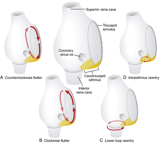
Lower loop reentry and intraisthmus reentry are macroreentrant circuits that are confined to the right atrium (RA) and incorporate the CTI as a critical part of the circuit. However, in contrast to typical AFL, the circuit is not peritricuspid (Fig. 13-1). Nevertheless, because the CTI is still a necessary part of the circuit, these arrhythmias are amenable to CTI ablation, as is true for patients with typical AFL.1
Lower Loop Reentry
Lower loop reentry is a form of CTI-dependent AFL with a reentrant circuit around the inferior vena cava (IVC); therefore, it is confined to the lower part of the RA (see Fig. 13-1). It often coexists with counterclockwise or clockwise typical AFL and involves posterior breakthrough across the crista terminalis. Lower loop reentry can rotate around the IVC in a counterclockwise (i.e., the impulse within the CTI travels from the septum to the lateral wall) or clockwise fashion. A breakdown in the inferoposterior boundaries of the CTI produced by the eustachian ridge and lower crista terminalis causes the circuit to revolve around the IVC (instead of around the tricuspid annulus), across the eustachian ridge, and through the crista terminalis, with slow conduction because of transverse activation through that structure. Alternatively, the circuit can exit at the apex of Koch triangle and come behind the eustachian ridge to break through across the crista terminalis behind the IVC and then return to the CTI. This arrhythmia is usually transient and terminates by itself or converts spontaneously into AFL or atrial fibrillation (AF).1
Intraisthmus Reentry
Intraisthmus reentry is a reentrant circuit usually occurring within the region bounded by the medial CTI and coronary sinus ostium (CS os; see Fig. 13-1). Circuits in the lateral portion of the CTI can also occur but are less common. This arrhythmia can be sustained and usually occurs in patients who have undergone prior, and often extensive, ablation at the CTI. Intracardiac recordings usually resemble typical AFL. However, in this form of CTI-dependent AFL, entrainment pacing from the lateral CTI demonstrates a post-pacing interval (PPI) longer than the tachycardia CL, a finding indicating that the lateral CTI is not part of the reentrant circuit. On the other hand, pacing from the region of medial CTI or CS os demonstrates concealed entrainment with PPI equal to the tachycardia CL. Fractionated or double potentials usually can be recorded in this area and can be entrained. Although the anatomical basis of this arrhythmia remains unknown, a linear lesion across the medial CTI, usually at the site of a very prolonged electrogram, can cure the tachycardia.
Non–Isthmus-Dependent Right Atrial Macroreentry
Lesional Right Atrial Macroreentrant Tachycardia
Atrial macroreentry in the right free wall is the most common form of non–CTI-dependent RA MRAT. These circuits can propagate around a central obstacle of a low-voltage area or scar in the lateral or posterolateral RA wall, arising spontaneously or as a consequence of prior atrial surgery.The central obstacle of the macroreentrant circuit can be an atriotomy scar (in patients who have undergone surgery for congenital or valvular heart disease), a septal prosthetic patch, a suture line, or a line of fixed block secondary to radiofrequency (RF) ablation. Other obstacles can also include anatomical structures located in the vicinity of the scar (superior vena cava [SVC], IVC). Occasionally, these ATs are associated with areas of electrical silence, a finding suggesting atrial scarring in patients who have not undergone prior atrial surgery. These patients have a characteristic posterolateral and lateral distribution of RA scarring and frequently have more than one tachycardia mechanism. Low-voltage electrograms characterizing areas of scar and double potentials characterizing a line of block can be observed during both normal sinus rhythm (NSR) and AT. In one study, electroanatomical mapping revealed that RA electrically silent areas (electrogram amplitude 0.03 mV or lower) were involved in the tachycardia mechanism in two thirds of the patients with non–CTI-dependent RA MRAT.2,3
Patients with congenital heart disease have a high prevalence of AT, particularly after they have undergone reparative or palliative surgical procedures. For MRATs in adults with repaired congenital heart disease, three RA circuits are generally identified: lateral wall circuits with reentry around or related to the lateral atriotomy scar, septal circuits with reentry around an atrial septal patch, and typical AFL circuits using the CTI. These arrhythmias are discussed separately in Chapter 14.1,4
Upper Loop Reentry
This type of MRAT involves the upper portion of the RA, with transverse conduction over the crista terminalis and wavefront collision occurring at a lower part of the RA or within the CTI. When upper loop reentry was first reported, it was thought to be a reentrant circuit using the channel between the SVC, fossa ovalis, and crista terminalis. Noncontact mapping studies have shown that this form of MRAT employs the crista terminalis as its functional central obstacle. The impulse rotating in the circuit can be in a counterclockwise or clockwise direction. The CTI is not an intrinsic part of the reentrant circuit. Upper loop reentry can be abolished by linear ablation of the gap in the crista terminalis.5,6
Dual-Loop Reentry
Although RA MRAT (lesional RA macroreentry or upper loop reentry) can manifest as an isolated arrhythmia (single-loop reentry), it can occur in conjunction with typical clockwise or counterclockwise AFL, or both, as well as lower loop reentry. When two atrial macroreentrant circuits coexist and use neighboring anatomical structures, they create the so-called dual-loop reentry. Not uncommonly, ablation of one tachycardia results in transition to the other, and ablation of both circuits is necessary for clinical success. Detection of this change requires careful attention to the atrial activation sequence and ECG pattern after each RF application. The recording of multiple simultaneous electrograms, as continuous endocardial references, facilitates detection of these activation changes. Fusion between two simultaneous left atrial (LA) macroreentrant circuits is possible after prior AF ablation.7
Left Atrial Macroreentry
LA MRATs are less common than typical AFL and are frequently related to or coexist with AF. LA MRAT is a known complication of surgical and catheter-based therapies of AF, and it can occur in up to 50% of patients following extensive catheter ablation strategies (see Chap. 15).8 Additionally, cardiac surgery involving the LA or atrial septum can produce different LA macroreentrant circuits. However, LA circuits also can be found in patients without a history of atriotomy or prior ablation. Electroanatomical maps in the latter group often show low-voltage or areas of scar in the LA, which act as a central obstacle or barrier in the circuit. These areas are typically located at the posterior wall (45%), superior region (roof, 28%), or anteroseptal region (27%) of the LA. The pathogenesis of these areas with no electrical signals is not well established. Potential causes include volume and pressure overload (mitral valve disease, hypertension, heart failure), ischemia (atrial branch occlusion), postinflammation scarring (after myocarditis), atrial amyloidosis, atrial dysplasia, and tachycardia-related structural remodeling. These macroreentrant circuits show considerable anatomical variability and frequently involve multiple simultaneous loops.1,2
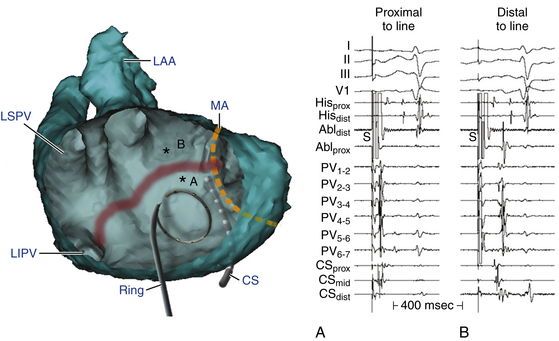
Perimitral Atrial Flutter
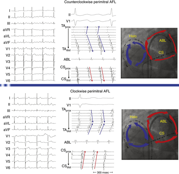
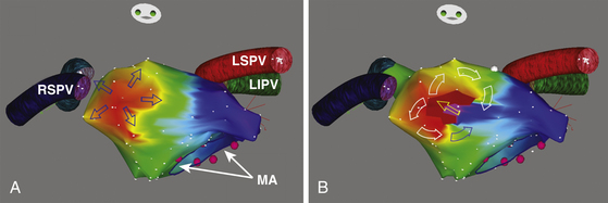
This circuit involves reentry around the mitral annulus in a counterclockwise or clockwise fashion (Fig. 13-2, see Video 12).  This arrhythmia is more common in patients with structural heart disease; however, it has been described in patients without obvious structural heart disease, but, in these patients, electroanatomical voltage mapping often shows scar or low-voltage areas on the posterior wall of the LA as a posterior boundary of this circuit. Perimitral MRAT is the most common MRAT in patients with prior LA ablation procedures for AF.

Left Septal Circuits
Left septal circuits represent a rare form of MRAT occurring in the absence of prior cardiac surgery. These circuits involve the LA septum primum, which acts as a central obstacle for the reentrant circuit. The right PV ostia serve as its posterior boundary, whereas the mitral annulus serves as its anterior boundary. Atrial dilation and concomitant antiarrhythmic drug therapy also seem to play a role by the prolongation of left intraatrial conduction, which then allows stable macroreentry circuits to persist.2 In patients with a history of surgery for atrial septal defects, scars or the patch on the septum can serve as the anatomical substrate of left septal circuits.
Clinical Considerations
Epidemiology
MRAT comprises a heterogeneous group of RA or LA macroreentrant circuits related to different anatomical and electrophysiological (EP) substrates. These arrhythmias are frequently associated with structural heart disease, congenital cardiac defects, previous cardiac surgical procedures, or surgical or catheter ablation procedures for AF. Often, these arrhythmias coexist with AF. However, MRAT occasionally occurs in a patient with no apparent structural heart disease.4
Although its exact prevalence among cardiac arrhythmias is difficult to establish clinically, MRAT is not a rare arrhythmia. It seems that the incidence of MRAT is increasing. This may be related to aging of the general population, which implies progressive alteration of the atrial electrical properties with development of an arrhythmogenic substrate, as well as to the increased numbers of surgical and catheter based procedures in the atria for treatment of AF.4,9
Principles of Management
With recent advances in the technology to visualize and modify the arrhythmia substrate, ablation of non–CTI-dependent MRAT has become increasingly successful, but it can be substantially more difficult than ablation of typical AFL. MRAT can have complex circuits that demand a thorough knowledge of atrial anatomy and a great deal of experience to correlate activation patterns with anatomical landmarks. When this type of AT is suspected, such as in patients with congenital heart disease who have had surgery, referral to an experienced center should be considered.4
Electrocardiographic Features
P wave morphology on the surface ECG is usually of limited value for precise anatomical localization of macroreentrant circuits. Analysis of the P wave can be impeded by partial or complete concealment of the P wave within the QRS complexes or T waves when the AT is associated with 1:1 or 2:1 AV conduction. Additionally, P wave morphology of a spectrum of RA and LA MRATs is highly variable. The presence of complex anatomy secondary to congenital abnormalities, prior atrial surgery, or a large low-voltage zone (secondary to underlying atrial substrate or extensive catheter or surgical atrial ablation) can modify atrial wavefront propagation in a nonuniform manner, resulting in deviated atrial activation vectors or low amplitude P waves. Furthermore, P waves produced by different underlying substrates may appear similar if the direction of activation of the atrial septum and LA is similar. The surface ECG morphology is most characteristic (and hence predictive) for establishing a diagnosis of counterclockwise typical AFL. Nevertheless, atypical ECG patterns have been described for typical AFL after AF ablation. Although clockwise typical AFL also has a characteristic appearance, this is more variable, and it can be mimicked by various other MRATs.5,10 On the other hand, AFL may show distinct isoelectric intervals between P waves, especially in the presence of extensive atrial scarring or a localized macroreentrant circuit, similar to focal AT.
Upper Loop Reentry
The surface ECG of upper loop reentry closely mimics that of clockwise typical AFL, with positive P waves in the inferior leads, because in most cases, both arrhythmias share a similar activation sequence of the LA, the septum, and caudocranial activation of the lateral RA. However, negative or isoelectric or flat P waves in lead I favor upper loop reentry over clockwise typical AFL. Conversely, positive P waves in lead I with an amplitude of more than 0.07 mV favor clockwise typical AFL. Additionally, the CL of upper loop reentry is usually shorter in comparison with typical AFL.5,6
Incisional Right Atrial Macroreentrant Tachycardia
The surface ECG morphology of free wall MRAT in a patient with a previous atriotomy is highly variable, depending on factors including the location of the scars and low-voltage areas, the direction of rotation, the presence of coexisting conduction block in the atrium, and the presence of a simultaneous typical AFL. The morphology of the atrial complex on the surface ECG can range from that similar to typical AFL to that characteristic of focal AT (see Fig. 14-5). Often, inverted P waves can be observed in lead V1. Depending on the predominant direction of septal activation, RA free wall MRAT can mimic either clockwise or counterclockwise typical AFL.5
Left Atrial Macroreentrant Tachycardia
The surface ECG morphology of LA MRAT caused by the different reentrant circuits is variable, and ECG findings are often similar for different underlying substrates, thus making the localization within the LA based on the ECG difficult. LA MRATs are usually associated with prominent positive P waves in lead V1 and upright (but frequently of low amplitude) deflections in leads II, III, and aVF. However, LA MRAT can result in ECG patterns of focal AT (discrete P waves and isoelectric baseline) because of a high prevalence of generalized atrial disease and slower conduction. Infrequently, LA MRAT can mimic typical AFL on the surface ECG.5
Perimitral Atrial Macroreentry
Most of these tachycardias show prominent forces in leads V1 and V2, with diminished amplitude in the inferior leads (see Fig. 13-2). It has been suggested that a posterior LA scar allows for domination by anterior LA forces. This constellation of findings may mimic counterclockwise or clockwise CTI-dependent AFL, but the decreased amplitude of frontal plane forces suggests an LA circuit. In patients with prior PV isolation procedures, the surface ECG morphology of counterclockwise perimitral MRAT can be different from that in patients without prior ablation, possibly related to varying degrees of prior LA ablation or scar. In these patients, counterclockwise perimitral MRAT demonstrates positive P waves in the inferior and precordial leads and a significant negative component in leads I and aVL. Furthermore, counterclockwise perimitral MRAT in these patients can have a morphology similar to that of left PV ATs. However, counterclockwise perimitral MRAT is suggested by a more negative component in lead I, an initial negative component in lead V2, and a lack of any isoelectric interval between P waves. Clockwise perimitral MRAT has limb lead morphology that is the converse of that of counterclockwise perimitral MRAT and an initial negative component in the lateral precordial leads. The positive P wave in leads I and aVL differentiates clockwise perimitral MRAT from counterclockwise CTI-dependent AFL and left PV AT.
Left Septal Circuits
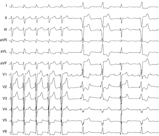
Because the reentry circuit is on the septum, the surface ECG shows prominent, usually positive, P waves only in lead V1 or V2 and almost flat waves in most other leads (Fig. 13-3). This pattern can be caused by a septal circuit with anteroposterior forces projecting in lead V1 and the cancellation of caudocranial forces. This pattern was 100% sensitive for an LA septal circuit, but the specificity of this pattern for any type of LA MRAT was only 64%.
Electrophysiological Testing
Induction of Tachycardia
The programmed electrical stimulation protocol should include atrial burst pacing from the high RA and CS—down to a pacing CL at which 2:1 atrial capture occurs—and atrial extrastimulation (AES), single and double, at multiple CLs (600 to 300 milliseconds) from the high RA and CS (down to the atrial effective refractory period). Isoproterenol infusion (0.5 to 4 μg/min) is administered as needed to facilitate tachycardia induction. The goals of EP testing in patients with MRAT are listed in Table 13-1.
TABLE 13-1 Goals of Programmed Stimulation during Macroreentrant Atrial Tachycardia
AT = atrial tachycardia; CL = cycle length; LA = left atrium; RA = right atrium.
Tachycardia Features
MRAT is characterized by a constant CL, P wave polarity, morphology, and amplitude of the recorded bipolar electrograms and by the presence of a single constant macroreentrant circuit with a constant atrial activation sequence. The atrial activation sequence and atrial CL depend on the origin and type of the macroreentrant circuit. However, considerable variation in the atrial CL for a single macroreentry circuit is unusual, although it can be observed in the atrium contralateral to atrium of origin of the tachycardia. In contrast, focal ATs classically exhibit alterations in CL with speeding (warm-up) and slowing (cool-down) at the onset and termination of tachycardia. Variation in the AT CL of greater than 15% has been suggested as a reliable marker of a focal AT. However, a regular AT can be either focal or macroreentrant.11 Additionally, focal ATs often manifest as bursts of tachycardia with spontaneous onset and termination, although they can be incessant, and they may accelerate in response to sympathetic stimulus.5 Several criteria can help distinguish focal AT from MRAT (see Table 11-5).
Atrial activation during MRATs spans the whole tachycardia CL. In contrast, intracardiac mapping in the setting of focal ATs shows significant portions of the tachycardia CL without recorded atrial activity, and atrial activation time is markedly less than the tachycardia CL, even when recording from the entire cardiac chamber of tachycardia origin (see Fig. 11-2). However, in the presence of complex intramyocardial conduction disturbances, activation during focal tachycardias can extend over a large proportion of the tachycardia CL, and conduction spread can follow circular patterns suggestive of macroreentrant activation.5 On the other hand, long isoelectric intervals can occur between P waves during MRATs, especially when mapping is limited to only the atrium contralateral to the origin of the macroreentrant circuit or to only parts of the ipsilateral atrium; a focal activation can be observed, incorrectly suggesting a focal mechanism. This is particularly observed for LA MRATs in the presence of large areas of electrical silence. However, a thorough intracardiac activation mapping reveals atrial activation spanning the tachycardia CL.
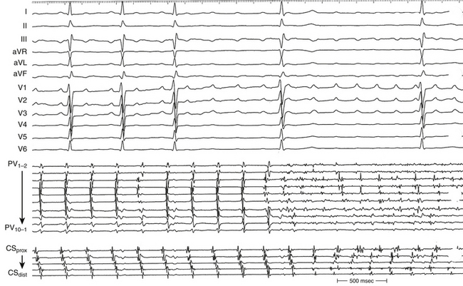
Occasionally, P wave morphology on the surface ECG resembles AFL, but intracardiac recordings show that parts of the atria (commonly the LA) have disorganized atrial activity (Fig. 13-4). Such rhythms behave more like AF than AT, but they may be converted to true typical AFL with antiarrhythmic drugs.
Diagnostic Maneuvers during Tachycardia
Atrial Extrastimulation
A focal mechanism is defined on the basis of dissociation of almost the entire atria from the tachycardia with AES. In contrast, the MRAT circuit usually incorporates large portions of the RA or LA, as demonstrated by resetting. In response to AES, MRATs typically demonstrate an increasing or mixed (flat, then increasing) resetting response. AES usually fails in terminating the AT. AES at short coupling intervals may result in transformation of the tachycardia into a different AT or AF. To minimize the risk to transform or interrupt tachycardia, atrial stimulation maneuvers during the tachycardia should be used sparingly and only when needed to confirm the diagnosis or more precisely localize the critical portion of the AT circuit as guided by the initial activation mapping.12
Atrial Pacing
Entrainment
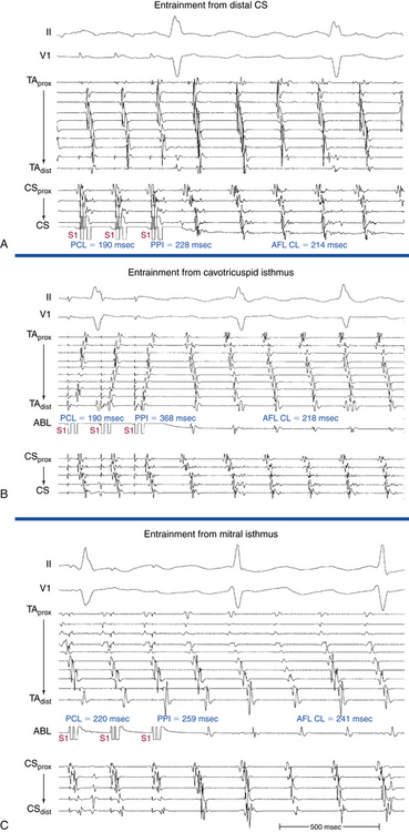
Overdrive atrial pacing at long CLs (i.e., 10 to 30 milliseconds shorter than the tachycardia CL) usually can entrain MRAT. The slower the pacing rate and the farther the pacing site from the reentrant circuit, the longer the pacing drive required to penetrate and entrain the tachycardia. Achievement of entrainment of the AT establishes a reentrant mechanism of the tachycardia and excludes triggered activity and abnormal automaticity as potential mechanisms (Fig. 13-5). Entrainment can also be used to estimate qualitatively how far the reentrant circuit is from the pacing site (see later).
Mapping
Because the reentrant circuit can involve any of multiple barriers, the usual anatomically guided ablation, as performed for typical CTI-dependent AFL, is not possible. Mapping is required to determine the precise circuit and define its vulnerable segment (critical isthmus) to provide a specifically tailored ablation solution. The goals of mapping of macroreentrant circuits include localization of the tachycardia circuit (RA versus LA), identification of possible lines of block, identification of an isthmus of tissue bounded between two long barriers, and determination of whether the line of block is a critical part of the circuit.
Activation Mapping
It is very important to ensure that the correct AT is being mapped at all points of time, and to remain vigilant to identify any change in CL or activation sequence that can result from catheter manipulation, pacing maneuvers, or ablation. Such changes can indicate transition to another tachycardia requiring reassessment. The transition may be obvious, but it is often quite subtle and sometimes imperceptible if only the CS activation is analyzed. Simultaneous recording RA activation (using a Halo catheter around the tricuspid annulus) and CS activation (using a decapolar catheter) can help rapid identification of tachycardia transformation.7
A change in ECG morphology without a change in the tachycardia CL can occur secondary to transformation of a multiple loop tachycardia by interruption of one loop, a change in bystander activation sufficient to be visible on the surface ECG (typified by the change in CS and LA activation observed during incomplete ablation of the CTI in counterclockwise typical AFL), a change from tachycardia in one atrium to that in the other (Fig. 13-6), or activation of the same circuit in the opposite direction (the last possible only if the first AT stops at least transiently).
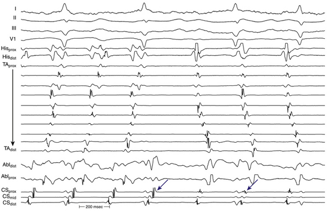
During LA MRATs, in the absence of LA mapping through transseptal catheterization, long segments of the tachycardia CL may not be covered by recorded electrograms. RA mapping typically shows nonreentrant activation patterns, clearly different from typical clockwise and counterclockwise AFL. Early RA septal activation relative to other parts of the RA can suggest a focal septal origin in some cases when LA recordings are not obtained (Fig. 13-7; see Fig. 13-2). Local RA conduction disturbances, such as CTI block (from prior isthmus ablation), transverse block at the crista terminalis, or both, can result in activation of the anterior and septal RA in opposite directions that mimics reentrant RA activation of typical AFL. In these cases, entrainment mapping clarifies the location of the reentrant circuit.13
The CS activation sequence has frequently been suggested as a useful way to determine the chamber of interest; however, this is not without limitations. Whereas in RA MRAT the CS is frequently activated from proximal to distal, this is not always true, particularly with MRAT localized to the superior RA. Similarly, although most circuits with distal to proximal activation of the CS are caused by LA MRAT, this sequence may also be seen in some cases of RA MRAT (see Fig. 13-2), and some LA MRATs (e.g., counterclockwise perimitral MRAT) can activate the CS proximally to distally.
Entrainment Mapping
Entrainment mapping provides information about sites of the RA or LA that are part of the reentrant circuit, those that are outside the circuit, and the critical isthmus in the macroreentrant circuit. Entrainment also qualitatively estimates how far the reentrant circuit is from the pacing site. However, before attempting to use entrainment methods for mapping, it is necessary first to demonstrate that the tachycardia can, in fact, be entrained, thus providing strong evidence that it is caused by reentry rather than by triggered activity or automaticity. At sites of entrainment, there should be confirmation of consistent capture of the atrium at the pacing CL for several beats, with minimal or no change in the surface morphology or intracardiac electrograms, and continuation of the identical tachycardia after pacing. Evaluation of the PPI or other criteria can be very misleading when the presence of true entrainment has not been established. Additionally, it is important to verify the absence of termination and reinitiation of the tachycardia during the same pacing drive.14
Once the presence of entrainment is verified, several criteria can be used to indicate the relation of the pacing site to the reentrant circuit. The first entrainment criterion to be sought is concealed fusion. Entrainment with concealed fusion indicates that the pacing site is in a protected isthmus located within or attached to the reentrant circuit.15,16
Whether this protected isthmus is crucial to the reentrant circuit or just a bystander site needs to be verified by other criteria, mainly comparing the PPI with the tachycardia CL and the stimulus-exit interval with the electrogram-exit interval. During entrainment from sites within the reentrant circuit, the orthodromic wavefront from the last stimulus propagates through the reentry circuit and returns to the pacing site, following the same path as the circulating reentry wavefronts. The conduction time required is the revolution time through the circuit. Thus, the PPI (measured from the pacing site recording) should be equal (within 20 milliseconds) to the tachycardia CL, given that conduction velocities and the reentrant path did not change during pacing. At sites remote from the circuit, the stimulated wavefronts propagate to the circuit, then through the circuit, and finally back to the pacing site. Thus, the PPI should equal the tachycardia CL plus the time required for the stimulus to propagate from the pacing site to the tachycardia circuit and back. The greater the difference is between the PPI and the tachycardia CL (PPI − AT CL), the longer the conduction time is between the pacing site and reentry circuit, and the greater the physical distance is between the pacing site and circuit. Features of entrainment when pacing from different sites are listed in Table 13-2.15,16
TABLE 13-2 Entrainment Mapping of Macroreentrant Atrial Tachycardia
1. Manifest atrial fusion on the surface ECG and intracardiac recordings (fixed fusion at a single pacing CL and progressive fusion on progressively shorter pacing CLs)
3. The interval between the stimulus artifact and the onset of the P wave on the surface ECG equals the interval between the local electrogram on the pacing site and the onset of the P wave on the surface ECG.
1. Concealed atrial fusion (i.e., paced atrial waveform on the surface ECG and intracardiac recordings is identical to the tachycardia waveform)
3. The interval between the stimulus artifact and the onset the P wave on the surface ECG equals the interval between the local electrogram on the pacing site and the onset of the P wave on the surface ECG.
AT = atrial tachycardia; CL = cycle length; PPI = post-pacing interval.
During entrainment of MRAT, the interval between the pacing stimulus and the onset of the P wave on the surface ECG reflects conduction time from the pacing site to the exit of the reentrant circuit (stimulus-exit interval), regardless of whether the pacing site is inside or outside the reentrant circuit, because activation starts at the pacing site and propagates in sequence to the circuit exit site. On the other hand, during tachycardia, the interval between the local electrogram at a given site and circuit exit (electrogram-exit interval) can reflect the true conduction time between those two sites if they are activated in sequence (which occurs when that particular site is located within the reentrant pathway), or can be shorter than the true conduction time if those two sites are activated in parallel (which occurs when that particular site is located outside the reentrant circuit). Because of frequent difficulty of determination of the onset of the P wave on the surface ECG, a reference intracardiac electrogram representing the exit of the circuit is usually used. Therefore, at any given pacing site, an electrogram-exit interval that is equal (± 20 milliseconds) to the stimulus-exit interval indicates that the pacing site lies within the reentry circuit and excludes the possibility that the site is a dead-end pathway attached to the circuit (i.e., not a bystander). On the other hand, pacing sites outside the reentrant circuit have an electrogram-exit interval significantly (more than 20 milliseconds) shorter than the stimulus-exit interval (see Table 13-2).
Electroanatomical Mapping
Electromagnetic three-dimensional (3-D) mapping (CARTO mapping system [Biosense Webster, Inc., Diamond Bar, Calif.] or EnSite NavX system [St. Jude Medical, St. Paul, Minn.]) can help distinguish between a focal origin and macroreentrant tachycardia by providing precise description of the macroreentrant circuit and sequence of atrial activation during the tachycardia and rapid visualization of the activation wavefront (see Videos 12 and 17).  This can contribute to the understanding of the reentrant circuit in relation to native barriers and surgical scars, identification of all slow-conducting pathways and appropriate sites for entrainment mapping, planning of ablation lines, navigation of the ablation catheter, and verification of conduction block produced by RF ablation.
Mapping Technique
Activation mapping is performed to define the atrial activation sequence. Reasonable numbers of points homogeneously distributed in the RA or LA, or both, must be recorded (80 to 100). Each point is tagged on the 3-D map as follows: The local activation time at each site is determined from the intracardiac bipolar electrogram and is measured in relation to the fixed intracardiac electrogram obtained from the CS (reference) catheter. Points are added to the map only if stability criteria in space and local activation time are met. The end-diastolic location stability criterion is a variation of less than 2 mm, and the local activation time stability criterion is less than 2 milliseconds. Lines of block (manifest as double potentials) are tagged for easy identification because they can serve as boundaries for a subsequent design of ablation strategies. Silent areas are defined as having an atrial potential amplitude lower than 0.05 mV and the absence of atrial capture at 20 mA. Such areas and surgically related scars, such as atriotomy scars in the lateral RA or atrial septal defect closure patches, are tagged as “scar” (see Figs. 14-1 and 14-2). At sites with double potential, entrainment of the tachycardia can help evaluate which potentials are captured by the pacing stimulus. Local activation times are then reviewed, and the apparent far-field signal is excluded from the activation maps. The activation map can also be used to catalog sites at which pacing maneuvers are performed during assessment of the tachycardia.
Activation Map
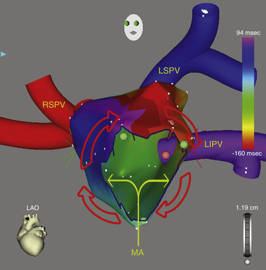
A continuous progression of colors (from red to purple in the CARTO system and from white to purple in the NavX system) around the RA (or LA), with close proximity of earliest and latest local activation, suggests the presence of an RA (or LA) macroreentrant tachycardia. In these cases, RA (or LA) activation time is in a similar range as the tachycardia CL (Fig. 13-8). Conversely, the electroanatomical maps of focal ATs demonstrate radial spreading of activation, from the earliest local activation site in all directions. In these cases, atrial activation time is markedly shorter than the tachycardia CL. When the onset of the window of interest is set at the mid-diastole between two consecutive P waves, the mid-diastolic isthmus of the reentrant circuit can be identified by the interface of early and late activation (i.e., the region where “early meets late” on the color-coded activation map). High-density mapping is then performed in and around the isthmus to define its limits and width precisely. It is important to recognize that if an insufficient number of points is obtained in the isthmus region, it may be falsely concluded through the interpolation of activation times that the wavefront propagates from a focal source (Fig. 13-9).9
Voltage Map
Voltage mapping is performed to define areas of electrical scars, which can be involved in the reentrant circuit and/or can potentially serve as boundaries for the subsequent design of ablation strategies. Silent areas are defined as having an atrial potential amplitude of less than 0.05 mV and the absence of atrial capture at 20 mA.
Electroanatomical Mapping of Post-Pacing Intervals
A graphical representation of entrainment mapping can be constructed by plotting the values of the [PPI − AT CL] differences on an electroanatomical mapping system (CARTO or NavX) to generate color-coded 3-D entrainment maps (see Fig. 13-1). This approach can potentially help accurately determine and visualize the 3-D location of the entire reentrant circuit, even though the area of slow conduction of the tachycardia is not described. Because neither of the electroanatomical mapping systems (CARTO, NavX) contains an algorithm for color-coding of entrainment information, the modus for activation mapping is altered manually.At each 3-D location of the catheter tip stored on the electroanatomical mapping system, entrainment stimulation is performed, and the difference between PPI and tachycardia CL (PPI − AT CL) is calculated and entered into the electroanatomical mapping system (as if it would be an “activation time”). For that, the local electrogram stored at the 3-D location is completely disregarded. The annotation marker is manually moved into a position where the numerical timing information equaled the entrainment information (PPI − tachycardia CL). That timing information then is displayed in a color-coded fashion as if it were activation time, but, in fact, it represents information on the length of the entrainment return cycle (see Fig. 13-1). With the color range, red (in CARTO) or white (in NavX) represents points closest to the reentrant circuit (i.e., sites with smaller [PPI – AT CL] differences, approaching 0, signifying their inclusion in the reentrant circuit), and purple represents points far away from the circuit (i.e., sites with the largest [PPI – AT CL] differences).14,17
Color-coded 3-D entrainment mapping allows determination of the full active reentrant circuit (versus passively activated regions of the chamber) and the obstacle around which the tachycardia is circulating, and it provides very useful information on the location of potential ablation sites. However, not all these sites terminate reentry; the final choice is determined by location of anatomical barriers and width of putative isthmuses, so that strategic ablation lines, mainly connecting to anatomical barriers, can be applied to transect the circuit and eliminate the arrhythmia.14,17
Noncontact Mapping
The EnSite 3000 system requires a 9 Fr multielectrode array and a 7 Fr mapping-ablation catheter. To create a map, the balloon catheter is positioned over a 0.035-inch guidewire under fluoroscopic guidance in the cardiac chamber of interest. The balloon is then deployed, and it can be filled with a mixture of contrast and saline to be visualized fluoroscopically. The balloon is positioned in the center of the atrium and does not come into physical contact with the atrial walls being mapped. The position of the array in the chamber must be secured to avoid significant movement that would invalidate the electrical and anatomical information. The array must be positioned as closely as possible (and in direct line of sight through the blood pool) to the endocardial surface being mapped, because the accuracy of the map is sensitive to the distance between the center of the balloon and the endocardium being mapped.18
Once chamber geometry has been delineated, tachycardia is induced, and mapping can begin. The data acquisition process is performed automatically by the system, and all data for the entire chamber are acquired simultaneously. The system then reconstructs more than 3000 unipolar electrograms simultaneously and superimposes them onto the virtual endocardium, to produce color-coded isopotential maps that graphically depict depolarized regions. Activation can be tracked on the isopotential map throughout the tachycardia cycle, and wavefront propagation can be displayed as a user-controlled 3-D “movie.” The color range represents voltage or timing of onset. A default high-pass filter setting of 2 Hz is used to preserve components of slow conduction on the isopotential map. When conduction through gaps in a line of block is very slow, the high-pass filter may be set at 1.0 to 0.5 Hz. Color settings are adjusted so that the color range matches 1 to 1 with the millivolt range of the electrogram deflection of interest. Isochronal maps can also be created that represent progression of activation throughout the chamber relative to user-defined electrical reference timing point. If the atrial electrograms overlap with the T wave, a ventricular extrastimulus may be delivered to accelerate ventricular depolarization and repolarization and reveal the following atrial complex without far-field interference.19
In addition, the system can simultaneously display as many as 32 electrograms as waveforms. Unipolar or bipolar electrograms (virtual electrograms) can be selected (at any given interval of the tachycardia cycle) by using the mouse from any part of the created geometry and displayed as waveforms as if from point, array, or plaque electrodes. The reconstructed electrograms are subject to the same electrical principles as contact catheter electrograms because they contain far-field electrical information from the surrounding endocardium, as well as the underlying myocardial signal vector, and distance from the point where the signal is generated to the array can affect the contribution to the electrogram. The maps are particularly useful for identifying slowly conducting pathways, such as the critical slow pathways and rapid breakthrough points of MRAT. The reentry circuit can be fully identified, along with other aspects such as the slowing, narrowing, and splitting of activation wavefronts in the isthmus. The locator technology used to collect the geometry information for the convex hull can then be used to guide an ablation catheter to the proper location in the heart. Ablation lesions can be tagged, thus facilitating performing linear ablation devoid of gaps across the tachycardia critical isthmus.19
Substrate mapping based on scar or diseased tissue, which has been introduced into noncontact mapping technology, can be of value in mapping and ablation of MRAT. Dynamic substrate mapping allows the creation of voltage maps from a single cardiac cycle and can identify low-voltage areas, as well as fixed and functional block, on the virtual endocardium through noncontact methodology. High-density voltage mapping of the atrial substrate is performed using the peak negative voltage of the reconstructed unipolar electrograms. An atrial substrate characterized by an abnormally low peak negative voltage (less than 30% of the maximal peak negative voltage) can potentially predict the slow conduction path within the protected isthmus of the MRAT. When combined with the activation sequence, substrate mapping provides essential information for guiding ablation, even when the arrhythmia is nonsustained.20
Practical Approach to Mapping Macroreentrant Atrial Tachycardia
Exclusion of Cavotricuspid Isthmus Dependence
Because CTI-dependent typical AFL is the most common MRAT, exclusion of the CTI as part of the reentrant circuit is an important initial step, even when the ECG pattern is not classically typical counterclockwise or clockwise AFL. In fact, typical AFL frequently manifests with an atypical 12-lead ECG appearance (so-called pseudoatypical flutter) in the setting of markedly abnormal atrial substrate. CTI-dependent AFL can be rapidly diagnosed or excluded by mapping of the tricuspid annulus and by entrainment maneuvers at the CTI. Exclusion of the CTI as part of the reentrant circuit can be established by any of the following: (1) demonstration of bidirectional activation of the CTI during AT, with resulting collision or fusion within the isthmus by activation from opposing directions (the low lateral RA and CS; see Fig. 13-2); (2) recording of double potentials separated by an isoelectric and constant interval throughout the full extent of the CTI during tachycardia; or (3) entrainment mapping from the CTI that demonstrates manifest atrial fusion with a long PPI (see Fig. 13-5).7
Localization of the Reentrant Circuit Chamber (Right Atrium Versus Left Atrium)
Electrocardiographic Findings
Lead V1 is the most useful lead for distinguishing LA from RA origin, but much overlap exists. In the absence of previous cardiac surgery or catheter ablation (particularly involving linear lesions in the LA), P waves that are completely negative or have an initial isoelectric (or inverted) component followed by an upright component in lead V1 is more frequently associated with RA free wall circuits. Conversely, in the absence of counterclockwise typical AFL, broad-based upright (or biphasic positive-negative) P waves in lead V1 are more frequently associated with LA circuits. LA circuits have also been reported to generate low-amplitude P waves frequently, with some of them having visible waves only in lead V1.5
Tachycardia Cycle Length Variations
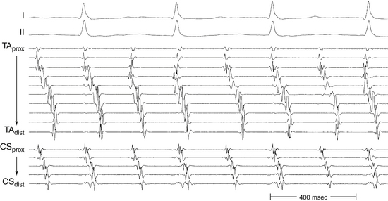
Large spontaneous variations (30 to 125 milliseconds) or even 2:1 conduction in the RA CL with concomitant variations of less than 20 milliseconds in CS recordings suggest an LA origin of the macroreentrant circuit (see Fig. 13-7).
Activation Mapping
As noted, when activation timing from 10 roughly evenly distributed sites in the RA, including 3 or 4 points at the tricuspid annulus, spans less than 50% of the tachycardia CL (in the absence of extensive RA scarring or prior CTI ablation), the arrhythmia is probably not located in the RA. In the setting of LA MRATs, RA mapping typically shows a nonreentrant activation pattern with early RA septal activation relative to other parts of the RA when LA recordings are not obtained (see Figs. 13-2 and 13-7). CS activation usually propagates in a proximal-to-distal direction in the setting of RA MRATs and in a distal-to-proximal direction in the setting of LA MRATs. However, this is not always true; MRATs localized to the superior RA can result in distal-to-proximal CS activation, and some LA MRATs (e.g., counterclockwise perimitral MRAT) can activate the CS in a proximal-to-distal direction (see Fig. 13-2).13
Identification of Barriers and Potential Lines of Block
Identification of the tachycardia circuit barriers is very important to help understand propagation of the reentrant activation wavefront in relation to these barriers, to identify the tachycardia critical isthmus, and to plan an ablation strategy to abolish the tachycardia. For RA macroreentry, the tricuspid annulus often provides one important barrier. Other naturally fixed barriers include the IVC, SVC, and CS os. For LA macroreentry, the mitral annulus and PVs often provide important barriers. Acquired barriers include surgical incisions or patches, surgical or catheter ablation lines, and atrial regions devoid of electrical activity (electrical scars). A line of block can be identified by the presence of double potentials, thus reflecting conduction up one side of the barrier and down the other side, with the bipolar electrogram recording both waves of activation. The use of an electroanatomical mapping system (CARTO or NavX) can facilitate tagging these anatomical and EP landmarks and understanding potential circuit routes, as well as performing voltage mapping to define areas of electrical scars.
Identification of the Complete Reentrant Circuit
Activation mapping is performed to define the atrial activation sequence. Reasonable numbers of points homogeneously distributed in the atrium of origin of the tachycardia must be recorded. Use of an electroanatomical mapping system (CARTO or NavX) can facilitate tagging each point on the 3-D map. The complete reentrant circuit is the spatially shortest route of unidirectional activation encompassing the complete CL of the tachycardia in terms of activation timing and returning to the site of earliest activation. Using electroanatomical mapping, this translates into continuous progression of colors (from red to purple in the CARTO system and from white to purple in the NavX system) around the atrium, with close proximity of earliest and latest local activation. Additionally, propagation of electrical activation superimposed on the 3-D anatomical reconstruction of the atrium can be visualized as a propagation map in relation to the anatomical and EP landmarks and barriers. For LA MRAT, activation mapping should be carefully carried out around the mitral annulus because this maneuver is easy to perform and identifies a common form of LA macroreentry, perimitral MRAT. If activation recorded at different atrial locations does not cover most of the tachycardia CL, two possibilities must be considered: focal AT and small, localized reentrant circuits (i.e., electrical activity accounting for more than 85% of the tachycardia CL is present within an area with a diameter of 3 cm or less). Identification of small circuits requires much more detailed activation mapping (see Fig. 13-9).
Additionally, entrainment mapping can be used to indicate the relation of pacing sites to the reentrant circuit, and it qualitatively estimates how far the reentrant circuit is from the pacing site. For RA MRAT, a [PPI – AT CL] difference of less than 50 milliseconds at the proximal CS distinguishes typical AFL from a lateral RA MRAT. With LA MRAT, a [PPI – AT CL] difference of less than 50 milliseconds at the proximal and distal CS distinguished perimitral MRAT from macroreentrant circuits involving the right PVs and septum.15 When entrainment does not localize the circuit in the LA or RA, a focal or small reentrant arrhythmia should be considered. Color-coded 3-D entrainment mapping can facilitate determination of the full active reentrant circuit (versus passively activated regions of the chamber) and the obstacle around which the tachycardia is circulating, and it provides very useful information on the location of potential ablation sites.
Identification of the Critical Isthmus
Once a scar or fixed barrier is localized, its role in supporting reentry is important in determining whether the isthmuses formed around it need ablation. Whether an isthmus is a critical part of the reentrant circuit can be determined by activation mapping during sustained stable reentry and entrainment mapping. The critical isthmus may lie between two anatomical landmarks (e.g., the mitral annulus and the left inferior PV), or it may be a relatively narrow channel bounded by sites of scar or double potentials. During electroanatomical activation mapping, when the onset of the window of interest is set at mid-diastole between two consecutive P waves, mid-diastolic isthmus of the reentrant circuit can be identified by the interface of early and late activation (i.e., the region where “early meets late” on the color-coded activation map). High-density mapping is then performed in and around the isthmus to define its limits and width precisely.9
For identification of the critical isthmus of the reentrant circuit, entrainment mapping is performed at selected atrial sites identified during activation mapping and propagation mapping in relation to atrial scars, barriers, and lines of block. Entrainment with concealed fusion should be sought, to indicate that the pacing site is in a protected isthmus located within or attached to the reentrant circuit. Whether this protected isthmus is crucial to the reentrant circuit or is just a bystander site needs to be verified by comparing the PPI with the tachycardia CL and the stimulus-exit interval with the electrogram-exit interval, as outlined in Table 10-2.15,16
Ablation
Target of Ablation
In patients with incomplete maps, the ablation is guided by activation, entrainment, and voltage mapping targeting a critical isthmus or a zone of slow conduction shown to be part of the circuit by pacing maneuvers.9,20
Contact or noncontact voltage maps can be used to guide the choice of the ablation site. The likelihood of achieving a complete and transmural ablation line is probably greater in low-amplitude areas.9,20
Left Atrial Macroreentry
In Setting of Previous Surgery or Spontaneous Regions of Scar
The goal is to localize the area with scar and extend this line of conduction block to an anatomical obstacle, or to transect the circuit by joining anatomical structures. Although this strategy is achievable in most of the atria, it is advisable to avoid attempting to connect the anterior septal region to the mitral annulus in the region of the low left septum because the thickness of the tissue prohibits complete lesions in approximately 40% of patients despite the use of irrigated-tip catheters. The exception to this is the presence of a narrow mid-diastolic isthmus (defined by activation, entrainment, and voltage mapping); this target is then preferable and usually much easier than longer linear lesions.
Macroreentrant Atrial Tachycardias Following Ablation of Atrial Fibrillation
Knowledge of the type of the initial ablation procedure is critical before embarking on LA AT ablation. ATs following PV isolation procedures can often be focal, typically originating from the vicinity of a reconnected PV.7 Most of the ATs complicating circumferential and linear LA ablations are macroreentrant, most commonly with circuits around the mitral annulus or involving the LA roof or septum. These circuits are most often related to gaps in ablation lines or to isthmuses created between the ablation lines and other obstacles in the LA. Multiple macroreentrant circuits and multiple-loop reentrant circuits are not infrequently encountered. Additionally, localized reentrant circuits are not uncommon, and they usually arise from the vicinity of the isolated PVs or linear lesions (see Video 17).21
Mapping and ablation of LA MRATs following circumferential LA ablation or circumferential PV isolation are frequently challenging. Detailed mapping with a high density of points is necessary to elucidate a more complete understanding of the activation pattern during the AT. In addition, mapping of the previously performed ablation lesions is critical to determine whether the ablation lines, PV isolation, or both, are complete. When the macroreentrant circuit can be mapped, ablation lesions should be tailored to interrupt the path of the reentrant circuit (see Fig. 15-59). In the absence of complete block across the old ablation lines, the gaps must be reablated. Empirical treatment of unmappable ATs primarily involves electrical isolation of all reconnected PVs and, if needed, empirical linear lesions within the tachycardia circuit, often including a line between the mitral annulus and left inferior PV and a line between the superior PVs.22
Perimitral Atrial Macroreentry
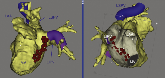
An ablation lesion connecting the mitral annulus and one other anatomical barrier (usually the left inferior PV; Fig. 13-10) or the posterior scar can eliminate this arrhythmia. Another option is to use an anterior line from the anterior mitral annulus to the ostium of the left superior PV or to a region of scar through the anterior LA.
Ablation Technique
During delivery of RF energy, the tachycardia can terminate, or its CL can increase transiently or permanently. These findings indicate that the lesions have affected the circuit and should lead to continuation of RF delivery or extension of the lesion to ensure the achievement of complete conduction block across the isthmus.
The coalescence of multiple RF lesions can be facilitated by any 3-D localization system (e.g., CARTO, NavX). Ablation sites may be tagged to permit visualization of the ablation line on the electroanatomical map. CARTO is also invaluable in localizing the gaps in the scar line through which the impulse can propagate. Focal ablation of these gaps can abolish the tachycardia.9,20
It is not uncommon for the arrhythmia mechanism to switch rather than terminate following successful ablation. A change in atrial activation sequence or P wave morphology or a sudden change in the atrial CL may indicate that the tachycardia that was being ablated has changed to a different loop or to a different tachycardia. In this setting, it is very important to reevaluate the mechanism and location of the new arrhythmia systematically by using activation and entrainment mapping and to move to the new target if necessary.12,23 However, the transition to a different loop of a tachycardia or to a different tachycardia may occur with no discernible change in the activation sequence among the atrial electrograms that are being recorded, P wave morphology, or CL. It is important to keep this in mind when ablation across an isthmus appears not to affect the tachycardia. The isthmus may have already been blocked and may no longer be participating in the tachycardia. This should be suspected if double potentials are present along the ablation line, and it is easily confirmed by entrainment mapping near the ablation line. If that site was confirmed previously to be part of the reentrant circuit (PPI – AT CL difference less than 20 milliseconds) and now it is outside the tachycardia circuit (PPI – AT CL difference more than 30 milliseconds), this finding indicates that the tachycardia circuit has changed.7
Ablation of the Mitral Isthmus
The mitral isthmus is short (2 to 4 cm), anatomically bounded by the mitral annulus, left inferior PV ostium, and superiorly by the LA appendage (see Fig. 13-10). The average thickness of the atrium along the mitral isthmus is 3.8 mm, with maximum thickness up to 7.7 mm. The CS muscle sleeve, present in up to 75% of patients, inserts into the LA inferior to the mitral isthmus and occasionally extends onto the mitral valve.24,25 Mitral isthmus ablation is performed by linear ablation to join the lateral mitral isthmus to the left inferior PV.
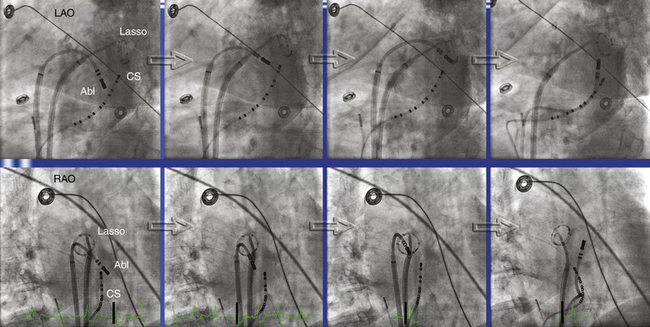
If possible, the CS catheter is positioned to bracket the planned linear lesion between its proximal and distal bipoles. The ablation catheter, bent with a 90- to 180-degree curve and introduced through a long sheath to achieve good contact and stability, is first positioned at the ventricular edge of the lateral mitral annulus, where the A:V electrogram shows a 1:1 to 2:1 ratio, to begin ablation. The sheath and catheter are then rotated clockwise to extend the lesion posteriorly, ending at the left inferior PV ostium (Fig. 13-11). In general, ablation is commenced at about the 3- or 4-o’clock position on the mitral isthmus and reaches the 2- to 3-o’clock position at the upper end of the line. A more anterior extension to the posterior root of the LA appendage occasionally is required.
RF energy is delivered with an 8-mm-tip catheter with a target temperature of 50° to 55°C and a power of 50 to 60 W. Externally irrigated catheters are preferably used with a power of 25 to 35 W and continuous titration of flow from 5 to 60 mL/min to achieve a target temperature of 40° to 42°C. Higher-power delivery in this region carries a significant risk of cardiac perforation with tamponade because of the particular regional anatomy, as well as the catheter-tissue geometry. The stability of the catheter is monitored during RF applications by using electrogram recordings and intermittent fluoroscopy to exclude inadvertent displacement, which could result in high-energy delivery in the left inferior PV ostium or LA appendage.12,23
Persisting epicardial conduction is suspected when the linear lesion results in adequate voltage abatement on the endocardial aspect and endocardial conduction delay recorded on the ablation catheter but not on the adjacent distal bipole of the CS catheter (anterolateral to the ablation line). Epicardial ablation within the CS is required to achieve block in approximately 70% of cases. The relatively low success rate of mitral isthmus block can be explained by several mechanisms. The shape and depth of the atrial myocardium vary greatly around the mitral isthmus, and the depth of the tissue (resulting from the double muscular layers of LA and CS) may be the limiting factor in achieving transmural lesion by endocardial ablation alone. Additionally, local cooling effects of blood flow in the circumflex coronary artery and the great cardiac vein (both pass in close proximity to the mitral isthmus) may act as a heat sink, preventing adequate tissue heating by RF delivery and making isthmus block difficult. Temporary displacement of the venous blood pool by using an air-filled CS balloon can potentially facilitate transmural mitral isthmus lesions during endocardial catheter ablation.24,26,27
When epicardial ablation is required, the ablation catheter is withdrawn from the LA and is introduced into the CS to map the epicardial side of the isthmus and identify fractionated or early potentials suggestive of an epicardial gap. Ablation within the CS is performed using an externally irrigated-tip catheter with a power limit of 20 to 25 W, and usually maximal flow (60 mL/min) is necessary (see Fig. 13-11).12,23 RF application should be discontinued if there is a rapid rise or fall in impedance or a rapid rise in temperature. Sometimes a power setting of 30 to 35 W is required for successful ablation. A higher power setting should be considered when a tachycardia fails to respond to ablation with 20 to 25 W and when entrainment mapping or activation mapping indicates that the CS is still an appropriate target site.7
One report described an alternative approach to ablation of perimitral MRAT. Linear ablation between the anterior-anterolateral mitral annulus and the ostium of the left superior PV (modified anterior line) was found to be safe, feasible, and successful in the short term in terminating perimitral MRAT in more than 96% of cases, and in achieving bidirectional block across the ablation line in 86% of cases, without the need for RF ablation within the CS. The ablation catheter is advanced through the transseptal sheath to the anterior-anterolateral mitral annulus, and delivery of RF lesions is started when the A/V ratio is 1:2. Linear ablation is then performed with clockwise (posterior) rotation of the transseptal sheath and progressive release of the ablation catheter curve. The ablation line is extended just medial to the orifice of the LA appendage, and it ends at the ostium of the left superior PV.28
Endpoints of Ablation
Confirmation of Mitral Isthmus Block
Several criteria are used to confirm the presence of bidirectional mitral isthmus block:
1. The presence of widely separated (by 150- to 300-millisecond intervals) local double potentials along the length of the ablation line during CS pacing septal of the ablation line.
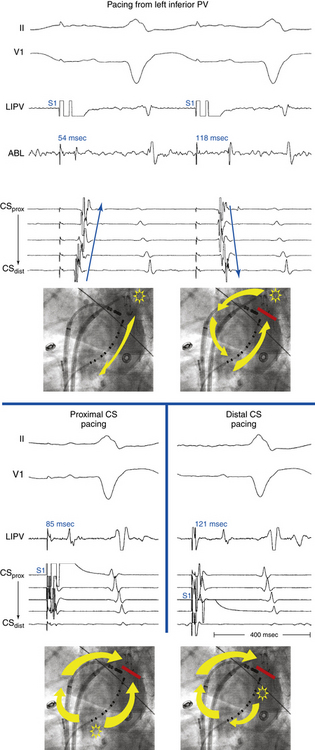
2. Mapping the activation detour during pacing from either side of the ablation line. Pacing on the septal side of the line through the CS demonstrates activation toward the line both septally and laterally. Pacing lateral to the line through the ablation catheter placed endocardially demonstrates a proximal-to-distal activation sequence along the CS septal side of the line, thus confirming bidirectional conduction block (Fig. 13-12). Such an activation detour can also be determined using 3-D electroanatomical mapping.
3. Differential pacing to distinguish slow conduction across the mitral isthmus from complete block. With the distal bipole of the CS catheter placed just septal to the linear lesion, the pacing site is changed from the distal to the proximal bipole of the CS catheter without moving any of the catheters. The stimulus-to-electrogram timing at a site lateral to the ablation line is measured before and after changing the pacing site. With complete block, the stimulus-to-electrogram interval is shortened after shifting the pacing site from the distal to proximal CS bipole (Fig. 13-13; see Fig. 13-12).
Confirmation of Modified Anterior Line Block
The achievement of a complete block along the modified anterior line can be verified by (1) mapping of the line during pacing from the distal CS or LA appendage and verification of the presence of double potentials along its entire length, (2) electroanatomical activation mapping during LA appendage pacing with earliest LA activation lateral to the ablation line and an early-meets-late zone along the entire length of the ablation line, or (3) evaluation of the CS activation pattern during pacing just laterally and medially to the line with the ablation catheter (translinear pacing maneuver). Complete linear block is confirmed if pacing laterally to the line results in a distal to proximal CS activation pattern, whereas after moving the catheter to the septal side of the line, the CS is activated from proximal to distal.28
Outcome
Safety of Right Atrial Macroreentry Ablation
Right phrenic nerve injury can be observed during ablation at the anterior aspect of the SVC and lateral RA. Pacing at a high output of 10 mA from the ablation catheter at the site without capture of the phrenic nerve and continuous pacing in the SVC to capture the phrenic nerve during RA ablation are reassuring, but their efficacy has never been assessed. Early recognition of phrenic nerve injury during RF delivery, based on cough, hiccup, or reduced diaphragmatic respiratory motion, allows the immediate interruption of the application prior to the onset of permanent injury and is associated with the rapid recovery of phrenic nerve function. Furthermore, limiting the power delivered to 20 to 25 W further minimizes the risk of this complication.
1. Garan H. Atypical atrial flutter. Heart Rhythm. 2008;5:618-621.
2. Anselme F. Macroreentrant atrial tachycardia: pathophysiological concepts. Heart Rhythm. 2008;5(Suppl):S18-S21.
3. Fiala M., Chovancik J., Neuwirth R., et al. Atrial macroreentry tachycardia in patients without obvious structural heart disease or previous cardiac surgical or catheter intervention: characterization of arrhythmogenic substrates, reentry circuits, and results of catheter ablation. J Cardiovasc Electrophysiol. 2007;18:824-832.
4. Triedman J.K. Atypical atrial tachycardias in patients with congenital heart disease. Heart Rhythm. 2008;5:315-317.
5. Medi C., Kalman J.M. Prediction of the atrial flutter circuit location from the surface electrocardiogram. Europace. 2008;10:786-796.
6. Yuniadi Y., Tai C.T., Lee K.T., et al. A new electrocardiographic algorithm to differentiate upper loop re-entry from reverse typical atrial flutter. J Am Coll Cardiol. 2005;46:524-528.
7. Morady F., Oral H., Chugh A. Diagnosis and ablation of atypical atrial tachycardia and flutter complicating atrial fibrillation ablation. Heart Rhythm. 2009;6(Suppl):S29-S32.
8. Kron J., Kasirajan V., Wood M.A., et al. Management of recurrent atrial arrhythmias after minimally invasive surgical pulmonary vein isolation and ganglionic plexi ablation for atrial fibrillation. Heart Rhythm. 2010;7:445-451.
9. De P.R., Marazzi R., Zoli L., et al. Electroanatomic mapping and ablation of macroreentrant atrial tachycardia: comparison between successfully and unsuccessfully treated cases. J Cardiovasc Electrophysiol. 2010;21:155-162.
10. Chugh A., Latchamsetty R., Oral H., et al. Characteristics of cavotricuspid isthmus-dependent atrial flutter after left atrial ablation of atrial fibrillation. Circulation. 2006;113:609-615.
11. Knecht S., Matsuo S., Lim K.-T., et al. Focal vs. macroreentrant atrial tachycardia after prior ablation: value of cycle length variability. Heart Rhythm. 2007;4(Suppl):S238.
12. Jais P., Matsuo S., Knecht S., et al. A deductive mapping strategy for atrial tachycardia following atrial fibrillation ablation: importance of localized reentry. J Cardiovasc Electrophysiol. 2009;20:480-491.
13. Steven D., Seiler J., Roberts-Thomson K.C., et al. Mapping of atrial tachycardias after catheter ablation for atrial fibrillation: use of bi-atrial activation patterns to facilitate recognition of origin. Heart Rhythm. 2010;7:664-672.
14. Santucci P.A., Varma N., Cytron J., et al. Electroanatomic mapping of postpacing intervals clarifies the complete active circuit and variants in atrial flutter. Heart Rhythm. 2009;6:1586-1595.
15. Miyazaki H., Stevenson W.G., Stephenson K., et al. Entrainment mapping for rapid distinction of left and right atrial tachycardias. Heart Rhythm. 2006;3:516-523.
16. Deo R., Berger R. The clinical utility of entrainment pacing. J Cardiovasc Electrophysiol. 2009;20:466-470.
17. Esato M., Hindricks G., Sommer P., et al. Color-coded three-dimensional entrainment mapping for analysis and treatment of atrial macroreentrant tachycardia. Heart Rhythm. 2009;6:349-358.
18. Tai C.T., Chen S.A. Noncontact mapping of the heart: how and when to use. J Cardiovasc Electrophysiol. 2009;20:123-126.
19. Higa S., Tai C.T., Lin Y.J., et al. Focal atrial tachycardia: new insight from noncontact mapping and catheter ablation. Circulation. 2004;109:84-91.
20. Huang J.L., Tai C.T., Lin Y.J., et al. Substrate mapping to detect abnormal atrial endocardium with slow conduction in patients with atypical right atrial flutter. J Am Coll Cardiol. 2006;48:492-498.
21. Takahashi Y., Takahashi A., Miyazaki S., et al. Electrophysiological characteristics of localized reentrant atrial tachycardia occurring after catheter ablation of long-lasting persistent atrial fibrillation. J Cardiovasc Electrophysiol. 2009;20:623-629.
22. Knecht S., Veenhuyzen G., O’Neill M.D., et al. Atrial tachycardias encountered in the context of catheter ablation for atrial fibrillation part II: mapping and ablation. Pacing Clin Electrophysiol. 2009;32:528-538.
23. Weerasooriya R., Jais P., Wright M., et al. Catheter ablation of atrial tachycardia following atrial fibrillation ablation. J Cardiovasc Electrophysiol. 2009;20:833-838.
24. Matsuo S., Wright M., Knecht S., et al. Peri-mitral atrial flutter in patients with atrial fibrillation ablation. Heart Rhythm. 2010;7:2-8.
25. Anousheh R., Sawhney N.S., Panutich M., et al. Effect of mitral isthmus block on development of atrial tachycardia following ablation for atrial fibrillation. Pacing Clin Electrophysiol. 2010;33:460-468.
26. Choi J.I., Pak H.N., Park J.H., et al. Clinical significance of complete conduction block of the left lateral isthmus and its relationship with anatomical variation of the vein of Marshall in patients with nonparoxysmal atrial fibrillation. J Cardiovasc Electrophysiol. 2009;20:616-622.
27. d’Avila A., Thiagalingam A., Foley L., et al. Temporary occlusion of the great cardiac vein and coronary sinus to facilitate radiofrequency catheter ablation of the mitral isthmus. J Cardiovasc Electrophysiol. 2008;19:645-650.
28. Sivagangabalan G., Pouliopoulos J., Huang K., et al. Comparison of electroanatomic contact and noncontact mapping of ventricular scar in a postinfarct ovine model with intramural needle electrode recording and histological validation. Circ Arrhythm Electrophysiol. 2008;1:363-369.
[/level-membership-for-cardiovascular-category][not-level-membership-for-cardiovascular-category]
Chapter 13 Macroreentrant Atrial Tachycardia (“Atypical Atrial Flutter”)
Pathophysiology
Atypical Isthmus-Dependent Right Atrial Macroreentry
Lower loop reentry and intraisthmus reentry are macroreentrant circuits that are confined to the right atrium (RA) and incorporate the CTI as a critical part of the circuit. However, in contrast to typical AFL, the circuit is not peritricuspid (Fig. 13-1). Nevertheless, because the CTI is still a necessary part of the circuit, these arrhythmias are amenable to CTI ablation, as is true for patients with typical AFL.1
Lower Loop Reentry
Lower loop reentry is a form of CTI-dependent AFL with a reentrant circuit around the inferior vena cava (IVC); therefore, it is confined to the lower part of the RA (see Fig. 13-1). It often coexists with counterclockwise or clockwise typical AFL and involves posterior breakthrough across the crista terminalis. Lower loop reentry can rotate around the IVC in a counterclockwise (i.e., the impulse within the CTI travels from the septum to the lateral wall) or clockwise fashion. A breakdown in the inferoposterior boundaries of the CTI produced by the eustachian ridge and lower crista terminalis causes the circuit to revolve around the IVC (instead of around the tricuspid annulus), across the eustachian ridge, and through the crista terminalis, with slow conduction because of transverse activation through that structure. Alternatively, the circuit can exit at the apex of Koch triangle and come behind the eustachian ridge to break through across the crista terminalis behind the IVC and then return to the CTI. This arrhythmia is usually transient and terminates by itself or converts spontaneously into AFL or atrial fibrillation (AF).1
Intraisthmus Reentry
Intraisthmus reentry is a reentrant circuit usually occurring within the region bounded by the medial CTI and coronary sinus ostium (CS os; see Fig. 13-1). Circuits in the lateral portion of the CTI can also occur but are less common. This arrhythmia can be sustained and usually occurs in patients who have undergone prior, and often extensive, ablation at the CTI. Intracardiac recordings usually resemble typical AFL. However, in this form of CTI-dependent AFL, entrainment pacing from the lateral CTI demonstrates a post-pacing interval (PPI) longer than the tachycardia CL, a finding indicating that the lateral CTI is not part of the reentrant circuit. On the other hand, pacing from the region of medial CTI or CS os demonstrates concealed entrainment with PPI equal to the tachycardia CL. Fractionated or double potentials usually can be recorded in this area and can be entrained. Although the anatomical basis of this arrhythmia remains unknown, a linear lesion across the medial CTI, usually at the site of a very prolonged electrogram, can cure the tachycardia.
Non–Isthmus-Dependent Right Atrial Macroreentry
Lesional Right Atrial Macroreentrant Tachycardia
Atrial macroreentry in the right free wall is the most common form of non–CTI-dependent RA MRAT. These circuits can propagate around a central obstacle of a low-voltage area or scar in the lateral or posterolateral RA wall, arising spontaneously or as a consequence of prior atrial surgery.The central obstacle of the macroreentrant circuit can be an atriotomy scar (in patients who have undergone surgery for congenital or valvular heart disease), a septal prosthetic patch, a suture line, or a line of fixed block secondary to radiofrequency (RF) ablation. Other obstacles can also include anatomical structures located in the vicinity of the scar (superior vena cava [SVC], IVC). Occasionally, these ATs are associated with areas of electrical silence, a finding suggesting atrial scarring in patients who have not undergone prior atrial surgery. These patients have a characteristic posterolateral and lateral distribution of RA scarring and frequently have more than one tachycardia mechanism. Low-voltage electrograms characterizing areas of scar and double potentials characterizing a line of block can be observed during both normal sinus rhythm (NSR) and AT. In one study, electroanatomical mapping revealed that RA electrically silent areas (electrogram amplitude 0.03 mV or lower) were involved in the tachycardia mechanism in two thirds of the patients with non–CTI-dependent RA MRAT.2,3
Patients with congenital heart disease have a high prevalence of AT, particularly after they have undergone reparative or palliative surgical procedures. For MRATs in adults with repaired congenital heart disease, three RA circuits are generally identified: lateral wall circuits with reentry around or related to the lateral atriotomy scar, septal circuits with reentry around an atrial septal patch, and typical AFL circuits using the CTI. These arrhythmias are discussed separately in Chapter 14.1,4
Upper Loop Reentry
This type of MRAT involves the upper portion of the RA, with transverse conduction over the crista terminalis and wavefront collision occurring at a lower part of the RA or within the CTI. When upper loop reentry was first reported, it was thought to be a reentrant circuit using the channel between the SVC, fossa ovalis, and crista terminalis. Noncontact mapping studies have shown that this form of MRAT employs the crista terminalis as its functional central obstacle. The impulse rotating in the circuit can be in a counterclockwise or clockwise direction. The CTI is not an intrinsic part of the reentrant circuit. Upper loop reentry can be abolished by linear ablation of the gap in the crista terminalis.5,6
Dual-Loop Reentry
Although RA MRAT (lesional RA macroreentry or upper loop reentry) can manifest as an isolated arrhythmia (single-loop reentry), it can occur in conjunction with typical clockwise or counterclockwise AFL, or both, as well as lower loop reentry. When two atrial macroreentrant circuits coexist and use neighboring anatomical structures, they create the so-called dual-loop reentry. Not uncommonly, ablation of one tachycardia results in transition to the other, and ablation of both circuits is necessary for clinical success. Detection of this change requires careful attention to the atrial activation sequence and ECG pattern after each RF application. The recording of multiple simultaneous electrograms, as continuous endocardial references, facilitates detection of these activation changes. Fusion between two simultaneous left atrial (LA) macroreentrant circuits is possible after prior AF ablation.7
Left Atrial Macroreentry
LA MRATs are less common than typical AFL and are frequently related to or coexist with AF. LA MRAT is a known complication of surgical and catheter-based therapies of AF, and it can occur in up to 50% of patients following extensive catheter ablation strategies (see Chap. 15).8 Additionally, cardiac surgery involving the LA or atrial septum can produce different LA macroreentrant circuits. However, LA circuits also can be found in patients without a history of atriotomy or prior ablation. Electroanatomical maps in the latter group often show low-voltage or areas of scar in the LA, which act as a central obstacle or barrier in the circuit. These areas are typically located at the posterior wall (45%), superior region (roof, 28%), or anteroseptal region (27%) of the LA. The pathogenesis of these areas with no electrical signals is not well established. Potential causes include volume and pressure overload (mitral valve disease, hypertension, heart failure), ischemia (atrial branch occlusion), postinflammation scarring (after myocarditis), atrial amyloidosis, atrial dysplasia, and tachycardia-related structural remodeling. These macroreentrant circuits show considerable anatomical variability and frequently involve multiple simultaneous loops.1,2
Perimitral Atrial Flutter
This circuit involves reentry around the mitral annulus in a counterclockwise or clockwise fashion (Fig. 13-2, see Video 12). This arrhythmia is more common in patients with structural heart disease; however, it has been described in patients without obvious structural heart disease, but, in these patients, electroanatomical voltage mapping often shows scar or low-voltage areas on the posterior wall of the LA as a posterior boundary of this circuit. Perimitral MRAT is the most common MRAT in patients with prior LA ablation procedures for AF.
Left Septal Circuits
Left septal circuits represent a rare form of MRAT occurring in the absence of prior cardiac surgery. These circuits involve the LA septum primum, which acts as a central obstacle for the reentrant circuit. The right PV ostia serve as its posterior boundary, whereas the mitral annulus serves as its anterior boundary. Atrial dilation and concomitant antiarrhythmic drug therapy also seem to play a role by the prolongation of left intraatrial conduction, which then allows stable macroreentry circuits to persist.2 In patients with a history of surgery for atrial septal defects, scars or the patch on the septum can serve as the anatomical substrate of left septal circuits.
Clinical Considerations
Epidemiology
MRAT comprises a heterogeneous group of RA or LA macroreentrant circuits related to different anatomical and electrophysiological (EP) substrates. These arrhythmias are frequently associated with structural heart disease, congenital cardiac defects, previous cardiac surgical procedures, or surgical or catheter ablation procedures for AF. Often, these arrhythmias coexist with AF. However, MRAT occasionally occurs in a patient with no apparent structural heart disease.4
Although its exact prevalence among cardiac arrhythmias is difficult to establish clinically, MRAT is not a rare arrhythmia. It seems that the incidence of MRAT is increasing. This may be related to aging of the general population, which implies progressive alteration of the atrial electrical properties with development of an arrhythmogenic substrate, as well as to the increased numbers of surgical and catheter based procedures in the atria for treatment of AF.4,9
Principles of Management
With recent advances in the technology to visualize and modify the arrhythmia substrate, ablation of non–CTI-dependent MRAT has become increasingly successful, but it can be substantially more difficult than ablation of typical AFL. MRAT can have complex circuits that demand a thorough knowledge of atrial anatomy and a great deal of experience to correlate activation patterns with anatomical landmarks. When this type of AT is suspected, such as in patients with congenital heart disease who have had surgery, referral to an experienced center should be considered.4
Electrocardiographic Features
P wave morphology on the surface ECG is usually of limited value for precise anatomical localization of macroreentrant circuits. Analysis of the P wave can be impeded by partial or complete concealment of the P wave within the QRS complexes or T waves when the AT is associated with 1:1 or 2:1 AV conduction. Additionally, P wave morphology of a spectrum of RA and LA MRATs is highly variable. The presence of complex anatomy secondary to congenital abnormalities, prior atrial surgery, or a large low-voltage zone (secondary to underlying atrial substrate or extensive catheter or surgical atrial ablation) can modify atrial wavefront propagation in a nonuniform manner, resulting in deviated atrial activation vectors or low amplitude P waves. Furthermore, P waves produced by different underlying substrates may appear similar if the direction of activation of the atrial septum and LA is similar. The surface ECG morphology is most characteristic (and hence predictive) for establishing a diagnosis of counterclockwise typical AFL. Nevertheless, atypical ECG patterns have been described for typical AFL after AF ablation. Although clockwise typical AFL also has a characteristic appearance, this is more variable, and it can be mimicked by various other MRATs.5,10 On the other hand, AFL may show distinct isoelectric intervals between P waves, especially in the presence of extensive atrial scarring or a localized macroreentrant circuit, similar to focal AT.
Upper Loop Reentry
The surface ECG of upper loop reentry closely mimics that of clockwise typical AFL, with positive P waves in the inferior leads, because in most cases, both arrhythmias share a similar activation sequence of the LA, the septum, and caudocranial activation of the lateral RA. However, negative or isoelectric or flat P waves in lead I favor upper loop reentry over clockwise typical AFL. Conversely, positive P waves in lead I with an amplitude of more than 0.07 mV favor clockwise typical AFL. Additionally, the CL of upper loop reentry is usually shorter in comparison with typical AFL.5,6
Incisional Right Atrial Macroreentrant Tachycardia
The surface ECG morphology of free wall MRAT in a patient with a previous atriotomy is highly variable, depending on factors including the location of the scars and low-voltage areas, the direction of rotation, the presence of coexisting conduction block in the atrium, and the presence of a simultaneous typical AFL. The morphology of the atrial complex on the surface ECG can range from that similar to typical AFL to that characteristic of focal AT (see Fig. 14-5). Often, inverted P waves can be observed in lead V1. Depending on the predominant direction of septal activation, RA free wall MRAT can mimic either clockwise or counterclockwise typical AFL.5
Left Atrial Macroreentrant Tachycardia
The surface ECG morphology of LA MRAT caused by the different reentrant circuits is variable, and ECG findings are often similar for different underlying substrates, thus making the localization within the LA based on the ECG difficult. LA MRATs are usually associated with prominent positive P waves in lead V1 and upright (but frequently of low amplitude) deflections in leads II, III, and aVF. However, LA MRAT can result in ECG patterns of focal AT (discrete P waves and isoelectric baseline) because of a high prevalence of generalized atrial disease and slower conduction. Infrequently, LA MRAT can mimic typical AFL on the surface ECG.5
Perimitral Atrial Macroreentry
Most of these tachycardias show prominent forces in leads V1 and V2, with diminished amplitude in the inferior leads (see Fig. 13-2). It has been suggested that a posterior LA scar allows for domination by anterior LA forces. This constellation of findings may mimic counterclockwise or clockwise CTI-dependent AFL, but the decreased amplitude of frontal plane forces suggests an LA circuit. In patients with prior PV isolation procedures, the surface ECG morphology of counterclockwise perimitral MRAT can be different from that in patients without prior ablation, possibly related to varying degrees of prior LA ablation or scar. In these patients, counterclockwise perimitral MRAT demonstrates positive P waves in the inferior and precordial leads and a significant negative component in leads I and aVL. Furthermore, counterclockwise perimitral MRAT in these patients can have a morphology similar to that of left PV ATs. However, counterclockwise perimitral MRAT is suggested by a more negative component in lead I, an initial negative component in lead V2, and a lack of any isoelectric interval between P waves. Clockwise perimitral MRAT has limb lead morphology that is the converse of that of counterclockwise perimitral MRAT and an initial negative component in the lateral precordial leads. The positive P wave in leads I and aVL differentiates clockwise perimitral MRAT from counterclockwise CTI-dependent AFL and left PV AT.
Left Septal Circuits
Because the reentry circuit is on the septum, the surface ECG shows prominent, usually positive, P waves only in lead V1 or V2 and almost flat waves in most other leads (Fig. 13-3). This pattern can be caused by a septal circuit with anteroposterior forces projecting in lead V1 and the cancellation of caudocranial forces. This pattern was 100% sensitive for an LA septal circuit, but the specificity of this pattern for any type of LA MRAT was only 64%.
Electrophysiological Testing
Induction of Tachycardia
The programmed electrical stimulation protocol should include atrial burst pacing from the high RA and CS—down to a pacing CL at which 2:1 atrial capture occurs—and atrial extrastimulation (AES), single and double, at multiple CLs (600 to 300 milliseconds) from the high RA and CS (down to the atrial effective refractory period). Isoproterenol infusion (0.5 to 4 μg/min) is administered as needed to facilitate tachycardia induction. The goals of EP testing in patients with MRAT are listed in Table 13-1.
TABLE 13-1 Goals of Programmed Stimulation during Macroreentrant Atrial Tachycardia
AT = atrial tachycardia; CL = cycle length; LA = left atrium; RA = right atrium.
Tachycardia Features
MRAT is characterized by a constant CL, P wave polarity, morphology, and amplitude of the recorded bipolar electrograms and by the presence of a single constant macroreentrant circuit with a constant atrial activation sequence. The atrial activation sequence and atrial CL depend on the origin and type of the macroreentrant circuit. However, considerable variation in the atrial CL for a single macroreentry circuit is unusual, although it can be observed in the atrium contralateral to atrium of origin of the tachycardia. In contrast, focal ATs classically exhibit alterations in CL with speeding (warm-up) and slowing (cool-down) at the onset and termination of tachycardia. Variation in the AT CL of greater than 15% has been suggested as a reliable marker of a focal AT. However, a regular AT can be either focal or macroreentrant.11 Additionally, focal ATs often manifest as bursts of tachycardia with spontaneous onset and termination, although they can be incessant, and they may accelerate in response to sympathetic stimulus.5 Several criteria can help distinguish focal AT from MRAT (see Table 11-5).
Atrial activation during MRATs spans the whole tachycardia CL. In contrast, intracardiac mapping in the setting of focal ATs shows significant portions of the tachycardia CL without recorded atrial activity, and atrial activation time is markedly less than the tachycardia CL, even when recording from the entire cardiac chamber of tachycardia origin (see Fig. 11-2). However, in the presence of complex intramyocardial conduction disturbances, activation during focal tachycardias can extend over a large proportion of the tachycardia CL, and conduction spread can follow circular patterns suggestive of macroreentrant activation.5 On the other hand, long isoelectric intervals can occur between P waves during MRATs, especially when mapping is limited to only the atrium contralateral to the origin of the macroreentrant circuit or to only parts of the ipsilateral atrium; a focal activation can be observed, incorrectly suggesting a focal mechanism. This is particularly observed for LA MRATs in the presence of large areas of electrical silence. However, a thorough intracardiac activation mapping reveals atrial activation spanning the tachycardia CL.
Occasionally, P wave morphology on the surface ECG resembles AFL, but intracardiac recordings show that parts of the atria (commonly the LA) have disorganized atrial activity (Fig. 13-4). Such rhythms behave more like AF than AT, but they may be converted to true typical AFL with antiarrhythmic drugs.
Diagnostic Maneuvers during Tachycardia
Atrial Extrastimulation
A focal mechanism is defined on the basis of dissociation of almost the entire atria from the tachycardia with AES. In contrast, the MRAT circuit usually incorporates large portions of the RA or LA, as demonstrated by resetting. In response to AES, MRATs typically demonstrate an increasing or mixed (flat, then increasing) resetting response. AES usually fails in terminating the AT. AES at short coupling intervals may result in transformation of the tachycardia into a different AT or AF. To minimize the risk to transform or interrupt tachycardia, atrial stimulation maneuvers during the tachycardia should be used sparingly and only when needed to confirm the diagnosis or more precisely localize the critical portion of the AT circuit as guided by the initial activation mapping.12
Atrial Pacing
Entrainment
Overdrive atrial pacing at long CLs (i.e., 10 to 30 milliseconds shorter than the tachycardia CL) usually can entrain MRAT. The slower the pacing rate and the farther the pacing site from the reentrant circuit, the longer the pacing drive required to penetrate and entrain the tachycardia. Achievement of entrainment of the AT establishes a reentrant mechanism of the tachycardia and excludes triggered activity and abnormal automaticity as potential mechanisms (Fig. 13-5). Entrainment can also be used to estimate qualitatively how far the reentrant circuit is from the pacing site (see later).
