Humidity and Bland Aerosol Therapy
After reading this chapter you will be able to:
 Describe how airway heat and moisture exchange normally occurs.
 State the effect dry gases have on the respiratory tract.
 State when to humidify and warm inspired gas.
 Describe how various types of humidifiers work.
 Describe how to enhance humidifier performance.
 State how to select and use humidifier heating and feed systems safely.

 Describe how to monitor patients receiving humidity therapy.
 Describe how to identify and resolve common problems with humidification systems.
 State when to apply bland aerosol therapy.
 Describe how large volume aerosol generators work.
 Identify the delivery systems used for bland aerosol therapy.
 Describe how to identify and resolve common problems with aerosol delivery systems.
 Describe how to perform sputum induction.
 State how to select the appropriate therapy to condition a patient’s inspired gas.
Vapors and mists have been used for thousands of years to treat respiratory disease. Modern respiratory care still uses these treatments at the bedside, in the form of water vapor (humidity) and bland water aerosols. Concepts of absolute and relative humidity are essential for understanding humidity therapy; these concepts are covered in Chapter 6. This chapter reviews the principles, methods, equipment, and procedures for using these concepts appropriately.
Humidity Therapy
Physiologic Control of Heat and Moisture Exchange
Heat and moisture exchange is a primary function of the upper respiratory tract, mainly the nose.1 The nose heats and humidifies gas on inspiration and cools and reclaims water from gas that is exhaled. The nasal mucosal lining is kept moist by secretions from mucous glands, goblet cells, transudation of fluid through cell walls, and condensation of exhaled humidity. The nasal mucosa is very vascular, actively regulating temperature changes in the nose and serving as an active element in promoting effective heat transfer. Similarly, the mucosa lining the sinuses, trachea, and bronchi aid in heating and humidifying inspired gases.
The mouth is less effective at heat and moisture exchange than the nose because of the low ratio of gas volume to moist and warm surface area and the less vascular squamous epithelium lining the oropharynx and hypopharynx. When a person inhales through the mouth at normal room temperature, pharyngeal temperatures are approximately 3° C less than when the person breathes through the nose, with 20% less relative humidity. During exhalation, the relative humidity of expired gas varies little between mouth breathing and nose breathing, but the mouth is much less efficient in reclaiming heat and water.2
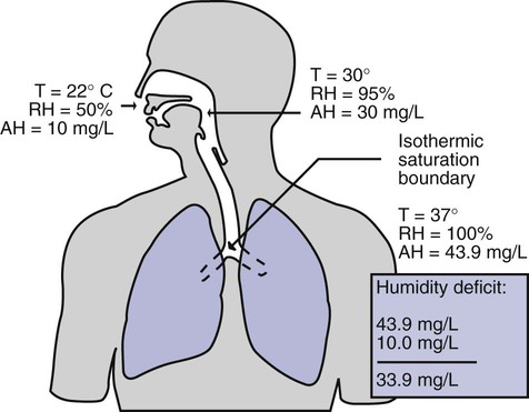
As inspired gas moves into the lungs, it achieves BTPS conditions (body temperature, 37° C; barometric pressure; saturated with water vapor [100% relative humidity at 37° C]) (Figure 35-1). This point, normally approximately 5 cm below the carina, is called the isothermic saturation boundary (ISB).3 Above the ISB, temperature and humidity decrease during inspiration and increase during exhalation. Below the ISB, temperature and relative humidity remain constant (BTPS).
Indications for Humidification and Warming of Inspired Gases
The primary goal of humidification is to maintain normal physiologic conditions in the lower airways. Proper levels of heat and humidity help ensure normal function of the mucociliary transport system. Humidity therapy is also used to treat abnormal conditions. Box 35-1 summarizes the primary and secondary indications for humidity therapy.
The hazard of breathing dry gas is even greater when the normal heat and water exchange capabilities of the upper airway are lost or bypassed, as occurs with endotracheal intubation.4 Breathing dry gas through an endotracheal tube can cause damage to tracheal epithelium within minutes. However, as long as the inspired humidity is at least 60% of BTPS conditions, no injury occurs in normal lungs.5,6 Prolonged breathing of improperly conditioned gases through a tracheal airway can result in hypothermia (reduced body temperature), inspissation of airway secretions, mucociliary dysfunction, destruction of airway epithelium, and atelectasis.7 Box 35-2 summarizes the signs and symptoms associated with breathing cold, dry gases.
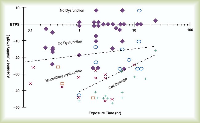
Figure 35-2 illustrates the level of dysfunction in the airway caused by changes in absolute humidity below BTPS and over hours of exposure. A reduction of 20 mg/L below BTPS (44 mg/L) is less than 60% relative humidity at BTPS.
The amount of heat and humidity that a patient needs depends on the site of gas delivery (e.g., nose or mouth, hypopharynx, trachea). Table 35-1 summarizes the recommended levels based on current standards.8
TABLE 35-1
Recommended Heat and Humidity Levels
| Delivery Site | Temperature Range (° C) | Relative Humidity (%) | Absolute Humidity (mg/L) |
| Nose/mouth | 20-22 | 50 | 10 |
| Hypopharynx | 29-32 | 95 | 28-34 |
| Trachea | 32-35 | 100 | 36-40 |
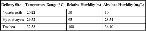
From Chatburn R, Primiano F: A rational basis for humidity therapy. Respir Care 32:249, 1987.
Warmed, humidified gases are used to prevent or treat various abnormal conditions. For treatment of a patient with hypothermia, heating and humidifying the inspired gas is one of several techniques used to raise core temperatures back to normal.9,10 Heated humidification is also used to prevent intraoperative hypothermia.11 Of possibly greater clinical significance, warming and humidifying the inspired gas can help alleviate bronchospasm in patients who develop airway narrowing after exercise or when they breathe cold air. Although the cause of this condition is not known for certain, the primary stimulus is probably a combination of airway cooling and drying, which leads to hypertonicity of airway lining fluid and the release of chemical mediators.12 Patients may reduce the incidence of cold air–induced bronchospasm by simply wearing a scarf over the nose and mouth when outside in cold weather; the scarf serves as a crude passive heat and moisture exchanger (HME).
Equipment
A humidifier is a device that adds molecular water to gas. This process occurs by evaporation of water from a surface (see Chapter 6), whether the water is in a reservoir, a wick, or a sphere of water in suspension (aerosol).
Physical Principles Governing Humidifier Function
The following four variables or principles affect the quality of performance of a humidifier: (1) temperature, (2) surface area, (3) time of contact, and (4) thermal mass. These factors are exploited to various degrees in the design of humidification devices (Box 35-3).
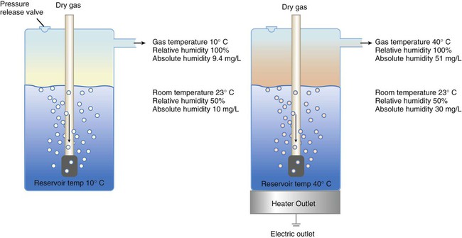
Temperature
Figure 35-3 shows this concept, where, owing to evaporative cooling, the unheated humidifier on the left is operating at 10° C. Although the humidifier fully saturates the gas, the low operating temperature limits total water vapor capacity to approximately 9.4 mg/L water vapor, equivalent to approximately 21% of body humidity. Simply heating the humidifier to 40° C (see Figure 35-3, right) increases its output to 51 mg/L, which is sufficient to meet BTPS conditions.
Types of Humidifiers
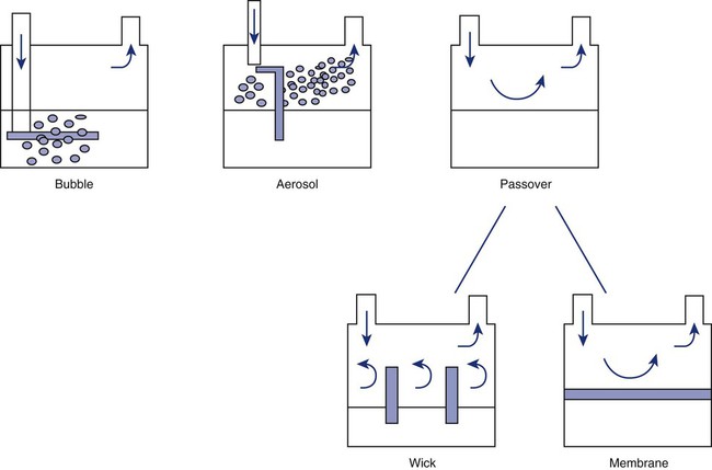
Humidifiers are either active (actively adding heat or water or both to the device-patient interface) or passive (recycling exhaled heat and humidity from the patient). Active humidifiers typically include (1) bubble humidifiers, (2) passover humidifiers, (3) nebulizers of bland aerosols, and (4) vaporizers. Passive humidifiers refer to typical heat and moisture exchangers (HMEs). Specifications covering the design and performance requirements for medical humidifiers are established by the American Society for Testing and Materials (ASTM).13
Active Humidifiers
Bubble
A bubble humidifier breaks (diffuses) an underwater gas stream into small bubbles (Figure 35-4). Use of a foam or mesh diffuser produces smaller bubbles than an open lumen, allowing greater surface area for gas/water interaction. Unheated bubble humidifiers are commonly used with oxygen (O2) delivery systems (see Chapter 38) to raise the water vapor content of the gas to ambient levels.
As indicated in Table 35-2, unheated bubble humidifiers can provide absolute humidity levels between approximately 15 mg/L and 20 mg/L.14–16 At room temperature, 10 mg/L absolute humidity corresponds to approximately 80% relative humidity but only approximately 25% body humidity (see Chapter 6). As gas flow increases, these devices become less efficient as the reservoir cools and contact time is reduced, limiting their effectiveness at flow rates greater than 10 L/min. Heating the reservoirs of these units can increase humidity content, but this is not recommended because the resulting condensate tends to obstruct the small bore delivery tubing to which these units connect.
TABLE 35-2
Absolute Humidity (mg/L) Provided by Unheated Bubble Humidifiers
| L/min | Aquapak 301 (Hudson RCI, Corp, Dunham, NC) | Traveral 500 (Baxter-Travenol, Corp, Deerfield, IL) |
| 2 | 17.6 | 20.4 |
| 4 | 17.7 | 19.5 |
| 6 | 16.9 | 16.2 |
| 8 | 14.9 | 15.7 |
Modified from Darin J, Broadwell J, MacDonell R: An evaluation of water-vapor output from four brands of unheated, prefilled bubble humidifiers. Respir Care 27:41, 1982.
To warn of flow-path obstruction and to prevent bursting of the humidifier bottle, bubble humidifiers incorporate a simple pressure-relief valve, or pop-off. Typically, the pop-off is either a gravity or spring-loaded valve that releases pressures greater than 2 psi. Humidifier pop-offs should provide both an audible and a visible alarm and should automatically resume normal position when pressures return to normal.13 The pop-off also can be used to test an O2 delivery system for leaks. If the system is obstructed at or near the patient interface and the pop-off sounds, the system is leak-free; failure of the pop-off to sound may indicate a leak (or a faulty pop-off valve).
At high flow rates, bubble humidifiers can produce aerosols. Although invisible to the naked eye, these water droplet suspensions can transmit pathogenic bacteria from the humidifier reservoir to the patient.17 Because any device that generates an aerosol poses a high risk of spreading infection, strict infection control procedures must be followed when using these systems (see Chapter 4).
Passover
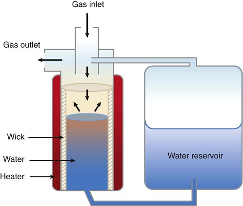
Passover humidifiers direct gas over a surface containing water. There are three common types of passover humidifiers: (1) simple reservoir type, (2) wick type, and (3) membrane type (see Figure 35-4).
A membrane-type humidifier separates the water from the gas stream by means of a hydrophobic membrane (see Figure 35-4). Water vapor molecules can easily pass through this membrane, but liquid water (and pathogens) cannot. As with a wick humidifier, bubbling does not occur. If a membrane-type humidifier were to be inspected while it was in use, no liquid water would be seen in the humidifier chamber.
Compared with bubble humidifiers, passover humidifiers offer several advantages.17,18 First, in contrast to bubble devices, passover humidifiers can maintain saturation at high flow rates. Second, they add little or no flow resistance to spontaneous breathing circuits. Third, they do not generate any aerosols, and they pose a minimal risk for spreading infection.
Heat and Moisture Exchangers
Traditionally, use of HMEs has been limited to providing humidification to patients receiving invasive ventilatory support via endotracheal or tracheostomy tubes. More recently, HMEs have been used successfully in meeting the short-term humidification needs of spontaneously breathing patients with tracheostomy tubes.19 Kapadia20 reviewed airway accidents in the intensive care unit for a 4-year period and noted an increasing trend in the incidence of blocked tracheal tubes, which was associated with an increased duration of HME filter use. More recent evidence supports long-term use of HMEs for spontaneously breathing patients.21
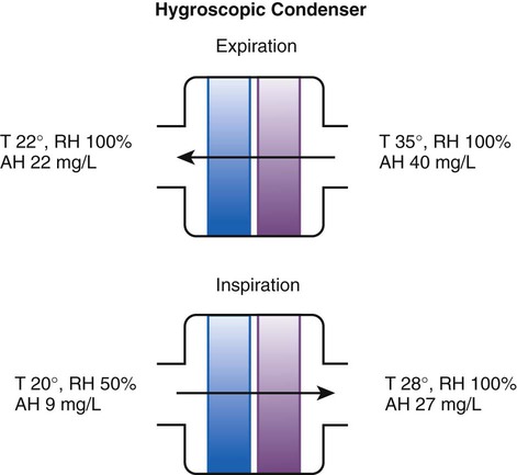
Hygroscopic condenser humidifiers provide higher efficiency by (1) using a condensing element of low thermal conductivity (e.g., paper, wool, foam) and (2) impregnating this material with a hygroscopic salt (calcium or lithium chloride). By using an element with low thermal conductivity, hygroscopic condenser humidifiers can retain more heat than simple condenser systems. In addition, the hygroscopic salt helps capture extra moisture from the exhaled gas. During exhalation, some water vapor condenses on the cool condenser element, whereas other water molecules bind directly to the hygroscopic salt. During inspiration, the lower water vapor pressure in the inspired gas liberates water molecules directly from the hygroscopic salt, without cooling. Figure 35-5 depicts the overall process of humidification with a hygroscopic condenser humidifier, showing the changes in temperature and the relative and absolute humidity occurring during the cycle of breathing. As shown, these devices typically achieve approximately 70% efficiency (40 mg/L exhaled, 27 mg/L returned).
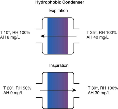
Hydrophobic condenser humidifiers use a water-repellent element with a large surface area and low thermal conductivity (Figure 35-6). During exhalation, the condenser temperature increases to approximately 25° C because of conduction and latent heat of condensation. On inspiration, cool gas and evaporation cools the condenser down to 10° C. This large temperature change results in the conservation of more water to be used in humidifying the next breath. The efficiency of these devices is comparable to hygroscopic condenser humidifiers (approximately 70%). However, some hydrophobic humidifiers that provide bacterial filtration may reduce the risk of pneumonia but be unsuitable for patients with limited respiratory reserve or who are prone to airway blockage because they may increase artificial airway occlusion.22,23
Design and performance standards for HMEs are set by the International Organization for Standardization (ISO).24 The ideal HME should operate at 70% efficiency or better (providing at least 30 mg/L water vapor); use standard connections; have a low compliance; and add minimal weight, dead space, and flow resistance to a breathing circuit.25 According to Lellouche and colleagues,26 HME performance varies from brand to brand, and only 37.5% of 32 HMEs tested in the study performed well. Table 35-3 compares performance of several commercially available HMEs according to their moisture output, flow resistance, and dead space.26
TABLE 35-3
Comparison of 25 Heat and Moisture Exchangers
| Device | Manufacturer | Measured AH (mg H2O/L) | AH/ml of Dead Space | Measured Resistance at 60 L/min cm H2O |
| Hygrovent | Peters | 31.9 ± 0.6 | 0.34 | 1.8 |
| Hygrobac | Mallinckrodt | 31.7 ± 0.7 | 0.33 | 2.1 |
| Hygrovent S | Peters | 31.7 ± 0.5 | 0.58 | 2.8 |
| Hygrobac S | Mallinckrodt | 31.2 ± 0.2 | 0.69 | 2.3 |
| 9000/100 | Allégiance | 31.2 ± 1.4 | 0.35 | 2.7 |
| Servo Humidifier 172 | Siemens | 30.9 ± 0.3 | 0.56 | NA |
| Humid Vent Filter | Hudson | 30.8 ± 0.3 | 0.88 | 2.3 |
| Hygroster | Mallinckrodt | 30.7 ± 0.6 | 0.32 | 2.3 |
| Humid Vent 2 | Hudson | 29.7 ± 0.4 | 1.03 | NA |
| Servo Humidifier 162 | Siemens | 29.7 ± 0.8 | 0.78 | NA |
| Humid Vent 2S | Hudson | 29.2 ± 0.4 | 1.01 | NA |
| 9040/01 | Allégiance | 28.6 ± 1.1 | 0.61 | 2.4 |
| 9000/01 | Allégiance | 28.5 ± 0.8 | 0.32 | 3.9 |
| BB100E | Pall | 27.2 ± 0.7 | 0.32 | 1.4 |
| BB100 | Pall | 26.8 ± 0.5 | 0.30 | 2.0 |
| Stérivent | Mallinckrodt | 23.8 ± 0.9 | 0.26 | 1.9 |
| Iso Gard Hepa Light | Hudson | 23.6 ± 0.3 | 0.47 | 2.4 |
| Stérivent S | Mallinckrodt | 22.2 ± 0.2 | 0.36 | 1.7 |
| BB25 | Pall | 19.6 ± 1.4 | 0.56 | 2.6 |
| BB2000AP | Pall | 18.9 ± 0.4 | 0.54 | 3.1 |
| Stérivent Mini | Mallinckrodt | 16.6 ± 1.0 | 0.47 | 2.2 |
| 4444/66 | Allégiance | 16.4 ± 0.6 | 0.35 | 3.4 |
| 4000/01 | Allégiance | 15.1 ± 0.9 | 0.40 | 2.2 |
| Barrierbac S | Mallinckrodt | 13.2 ± 0.2 | 0.38 | 2.1 |
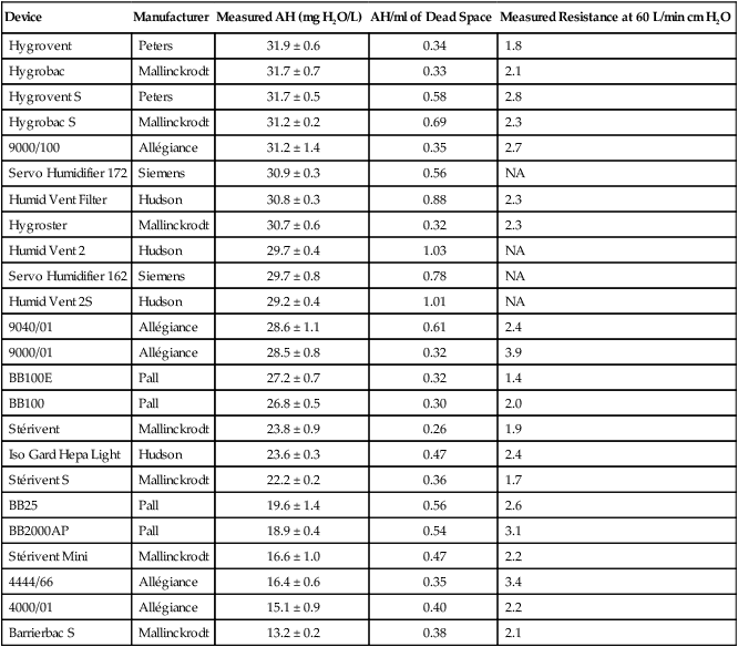
AH, Absolute humidity; NA, not available.
Modified from Lellouche F, Taille S, Lefrancois F, et al: Humidification performance of 48 passive airway humidifiers: comparison with manufacturer data. Chest 135:276, 2009.
As shown in Table 35-3, the moisture output of HMEs tends to decrease at high volumes and rates of breathing. In addition, high inspiratory flows and high FiO2 levels can decrease HME efficiency.25 Flow resistance through the HME also is important. When an HME is dry, resistance across most devices is minimal. However, because of water absorption, HME flow resistance increases after several hours of use.27,28 For some patients, the increased resistance imposed by the HME may not be well tolerated, in particular, if the underlying lung disease already causes increased work of breathing.
Because HMEs eliminate the problem of breathing circuit condensation, many clinicians consider these devices (especially hydrophobic filter HMEs) to be helpful in preventing nosocomial infections and ventilator-associated pneumonia.29 Compared with active humidification systems, HMEs do reduce bacterial colonization of ventilator circuits.30 However, circuit colonization plays a minor role in the development of nosocomial infections, provided that usual maintenance precautions are applied.31 Evidence indicates no difference in incidence of ventilator-associated pneumonia, mortality, morbidity, and respiratory complications among patients managed with HMEs and heated humidifiers.23,26,30,32,33
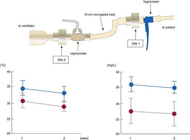
The position of the HME relative to the patient’s airway can affect its ability both to heat and to humidify inhaled gas. Secretions can foul HMEs attached directly to the airway. The use of devices such as closed suction catheters and airway monitor ports requires placement of the HME closer to the ventilator. Inui and colleagues34 tested performance of HMEs placed directly at the airway, 10 cm away from endotracheal tube and proximal to the ventilator circuit. HME performance was best at the airway for both HMEs tested, but one HME model exceeded recommended performance standards (≥30 mg/L absolute humidity and ≥30° C) at both sites, whereas the other model did not perform adequately at either position (Figure 35-7). Clinicians should select HMEs that perform adequately when placed at the intended HME site. Although use of HMEs has been associated with thickened and increased volume of secretions in some patients, the incidence of endotracheal tube occlusion when HMEs are used is lower than when heated humidifiers are used.35,36
Active Heat Moisture Exchangers
Active HMEs add humidity or heat or both to inspired gas by chemical or electrical means.37 The Humid-Heat (Louis Gibeck AB, Upplands Väsby, Sweden) consists of a supply unit with a microprocessor, water pump, and humidification device, which is placed between the Y-piece and the endotracheal tube. The humidification device is based on a hygroscopic HME, which absorbs the expired heat and moisture and releases it into the inspired gas. External heat and water are added to the patient side of the HME, so the inspired gas should reach 100% humidity at 37° C (44 mg H2O/L air). The external water is delivered to the humidification device via a pump onto a wick and evaporated into the inspired air by an electrical heater. The microprocessor controls the water pump and the heater by an algorithm using the minute ventilation (which is fed into the microprocessor) and the airway temperature measured by a sensor mounted in the flex-tube on the patient side of the humidification device. The HME Booster (King Systems, Noblesville, IN) has a T-piece containing an electrically heated element that was designed for use as an adjunct to a passive HME. The heating element heats water so that water vapor passes into the airway between the artificial airway and the endotracheal tube, via a Gore-Tex membrane and aluminum. Using a gravity feedbag via a flow regulator that limits flow to 10 mL/hr, water is fed to the heater, which operates at 110° C and adds 3 to 5.5 mg/L of humidity and 3° C to 4° C to inspired gas compared with HME alone. The Humid-Booster was designed for patients with minute volumes of 4 to 20 L, and it is not appropriate for use with pediatric patients or infants. Active HMEs add weight and complexity at the patient airway.
Heating Systems
Humidifier heating systems have a controller that regulates the element’s electrical power. In the simplest systems, the controller monitors the heating element, varying the delivered current to match either a preset or an adjustable temperature. In these systems, the temperature of the patient’s airway has no effect on the controller. Conversely, a servo-controlled heating system monitors temperature at or near the patient’s airway using a thermistor probe. The controller adjusts heater power to achieve the desired airway temperature. Both types of controller units usually incorporate alarms and alarm-activated heater shutdown. Box 35-4 outlines key features of modern heated humidification systems.38
 Rule Of Thumb
Reservoir and Feed Systems
Automatic Systems
Automatic feed systems avoid the need for constant checking and manual refilling of humidifiers. The simplest type of automatic feed system is the level-compensated reservoir (Figure 35-8). In these systems, an external reservoir is aligned horizontally with the humidifier, maintaining relatively consistent water levels between the reservoir and the humidifier chamber.
 Problem
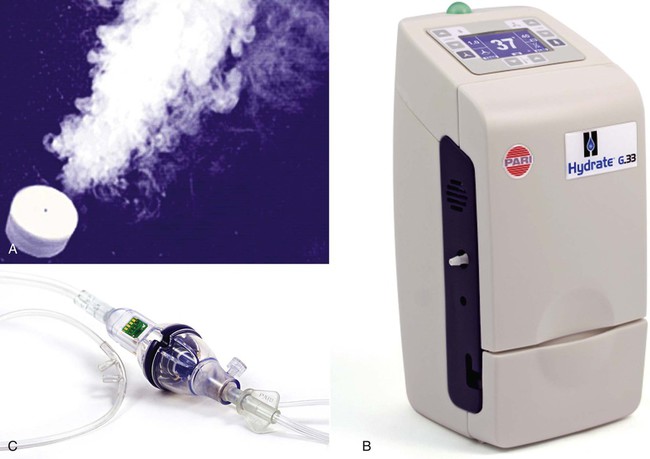
The Hydrate (Pari Respiratory Equipment, Midlothian, VA) capillary force vaporizer is driven by software that controls a heater element and water flow. The 19-mm diameter disc can deliver 2.2 mg of water vapor/min at 37° C. Data from prototypes suggest temperature control from 33° C to 41° C for flows 2 to 40 L/min (Figure 35-9).39
To guide practitioners in applying humidity therapy during ventilatory support, the American Association for Respiratory Care (AARC) has published Clinical Practice Guideline: Humidification During Mechanical Ventilation; excerpts from the AARC guideline appear in Clinical Practice Guideline 35-1.7
Setting Humidification Levels
Although the American National Standards Institute (ANSI) recommends minimum levels of humidity for intubated patients (>30 mg/L), there is less guidance regarding appropriate settings for optimal humidification. One suggestion is to target the temperature and level of humidity for normal conditions at the point that the gas is entering the airway. For example, the humidity of air entering the carina is typically 35 to 40 mg/L. When humidifiers run too cold (<32° C), humidity can be reduced to the point of increased airway plugging. Not all active heated humidifiers perform the same under all conditions. Nishida40 compared the performance of four active humidifiers (MR290 with MR730 [Fisher & Paykel Healthcare Inc, Laguna Hills, CA], MR310 with MR730 [Fisher & Paykel Healthcare Inc], ConchaTherm IV [Hudson RCI, Temecula, CA], and Hummax II), which were set to maintain the temperature of the airway opening at 32° C and 37° C under various ventilator parameters. The greater the minute ventilation, the lower the humidity delivered with all devices except the Hummax II. When the airway temperature control of the devices was set at 32° C, the ConchaTherm IV, the MR 310, and the MR 730 all failed to deliver 30 mg/L of vapor, which is the value recommended by ANSI. This study emphasizes the need to set humidifiers to maintain airway temperatures between 35° C and 37° C.
Controversy exists regarding the appropriate temperature and humidity of inspired gas delivered to mechanically ventilated patients with artificial airways. The current AARC Clinical Practice Guideline recommends 33° C, within 2° C, with a minimum of 30 mg/L of water vapor. In a comprehensive review, Williams41 suggested that inspired humidity be maintained at an optimal level, 37° C with 100% relative humidity and 44 mg/L, to minimize mucosal dysfunction. Theoretically, optimal humidity offers improved mucociliary clearance. The benefits of this strategy are theory based but have yet to be shown conclusively in the clinical setting. Further controlled studies are needed to support better the need for optimal humidity.
Problem Solving and Troubleshooting
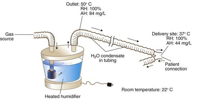
Condensation
Figure 35-10 provides an example of the condensation process. In this case, because of cooling along the circuit, the humidifier temperature has to be set to a higher level (50° C) than desired at the airway. At 50° C, the humidifier fully saturates the gas to an absolute humidity level of 84 mg/L of water. As cooling occurs along the tubing, the capacity of the gas to hold water vapor decreases. By the time the gas reaches the patient, the temperature of the gas has decreased to 37° C, and it is holding only 44 mg/L of water vapor. Although BTPS conditions have been achieved, 40 mg/L, half the total output of the humidifier (84 mg/L − 44 mg/L = 40 mg/L), has condensed in the inspiratory limb of the circuit.
Typically, patients contaminate ventilator circuits within hours, and condensate is colonized with bacteria and poses an infection risk.42 To avoid problems in this area, health care personnel should treat all breathing circuit condensate as infectious waste. See Chapters 4 and 43 for more detail on control procedures used with breathing circuits, including the AARC Clinical Practice Guideline on changing ventilator circuits (see Clinical Practice Guideline 4-1).
 Rule Of Thumb
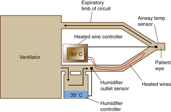
Most heated wire circuits use dual controllers with two temperature sensors: one monitoring the temperature of gas leaving the humidifier and the other placed at or near the patient’s airway (Figure 35-11). The controller regulates the temperature difference between humidifier output and patient airway. When heated wire circuits are used, the humidifier heats gas to a lower temperature (32° C to 40° C) than with conventional circuits (45° C to 50° C). The reduction in condensate in the tubing results in less water use, reduced need for drainage, and less infection risk for patients and health care workers.
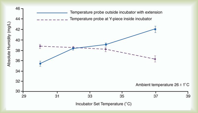
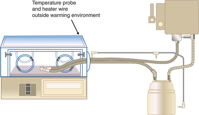
Use of heated wire circuits in neonates is complicated by the use of incubators and radiant warmers. Incubators provide a warm environment surrounding the infant and radiant warmers use radiant energy to warm objects that intercept radiant light. In both cases, a temperature probe placed in the heated environment would affect humidifier performance, resulting in reduced humidity received by the patient. Figure 35-12 shows the impact of temperature probe placement, in or out of the incubator, on absolute humidity delivered to the neonate. Consequently, temperature probes should always be placed outside of the radiant field or incubator (Figure 35-13).
Cross Contamination
Aerosol and condensate from ventilator circuits are known sources of bacterial colonization.42 However, advances in both circuit and humidifier technology have reduced the risk of nosocomial infection when these systems are used. Wick-type or membrane-type passover humidifiers prevent formation of bacteria-carrying aerosols. Heated wire circuits reduce production and pooling of condensate within the circuit. In addition, the high reservoir temperatures in humidifiers are bactericidal.43 In ventilator circuits using wick-type humidifiers with heated wire systems, circuit contamination usually occurs from the patient to the circuit, rather than vice versa.
For decades, the traditional way to minimize the risk of circuit-related nosocomial infection in critically ill patients receiving ventilatory support was to change the ventilator tubing and its attached components every 24 hours.44 It is now known that frequent ventilator circuit changes increase the risk of nosocomial pneumonia.45 Current research indicates that there is minimal risk of ventilator-associated pneumonia with weekly circuit changes and that there may be no need to change circuits at all.30,31,46,47 In addition, substantial cost savings can accrue with decreased frequency of circuit changes.
Proper Conditioning of Inspired Gas
Many heated wire humidification systems have a humidity control. This control does not reflect either absolute or relative humidity but only the temperature differential between the humidifier and the airway sensor. If the heated wires are set warmer than the humidifier, less relative humidity is delivered to the patient. To ensure that the inspired gas is being properly conditioned, clinicians should always adjust the temperature differential to the point that a few drops of condensation form near the patient connection, or “wye.” Lacking direct measurement of humidity, observation of this minimal condensate is the most reliable indicator that the gas is fully saturated at the specified temperature. If condensate cannot be seen, there is no way of knowing the level of relative humidity without direct measurement—it could be anywhere between 99% and 0%. HME performance can be evaluated in a similar manner.48
 Rule Of Thumb
Bland Aerosol Therapy
Humidity is simply water in the gas phase, whereas a bland aerosol consists of liquid particles suspended in a gas (see Chapter 36 for details on aerosol physics). Bland aerosol therapy involves the delivery of sterile water or hypotonic, isotonic, or hypertonic saline aerosols. Bland aerosol administration may be accompanied by O2 therapy. To guide practitioners in applying this therapy, the AARC has published Clinical Practice Guideline: Bland Aerosol Administration; excerpts appear in Clinical Practice Guideline 35-2.49
Equipment for Bland Aerosol Therapy
Aerosol Generators
Large Volume Jet Nebulizers
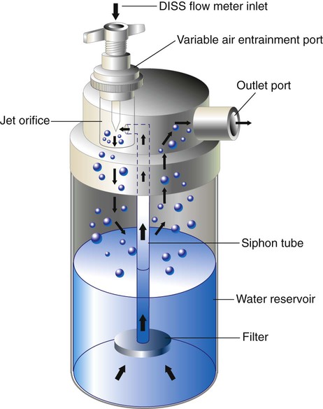
A large volume jet nebulizer is the most common device used to generate bland aerosols. As depicted in Figure 35-14, these devices are pneumatically powered, attaching directly to a flowmeter and compressed gas source. Liquid particle aerosols are generated by passing gas at a high velocity through a small “jet” orifice. The resulting low pressure at the jet draws fluid from the reservoir up to the top of a siphon tube, where it is sheared off and shattered into liquid particles. The large, unstable particles fall out of suspension or impact on the internal surfaces of the device, including the fluid surface (baffling). The remaining small particles leave the nebulizer through the outlet port, carried in the gas stream. A variable air-entrainment port allows air mixing to increase flow rates and to alter FiO2 levels (see Chapter 38).
Depending on the design, input flow, and air-entrainment setting, the total water output of unheated large volume jet nebulizers varies between 26 mg H2O/L and 35 mg H2O/L. When heated, output increases to between 33 mg H2O/L and 55 mg H2O/L, mainly because of increased vapor capacity.49,50 Larger versions of these devices (with 2-L to 3-L reservoirs) are used to deliver bland aerosols into mist tents. These enclosure systems can generate flow rates faster than 20 L/min, with water outputs of 5 ml/min (300 ml/hr). Because heat buildup in enclosures is a problem, these systems are always run unheated.
Ultrasonic Nebulizers
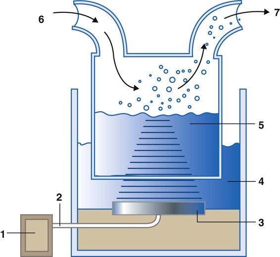
A USN is an electrically powered device that uses a piezoelectric crystal to generate aerosol. This crystal transducer converts radio waves into high-frequency mechanical vibrations (sound). These vibrations are transmitted to a liquid surface, where the intense mechanical energy creates a cavitation in the liquid, forming a standing wave, or “geyser,” which sheds aerosol droplets. Figure 35-15 provides a schematic of a large volume USN. Output from a radiofrequency generator is transmitted over a shielded cable to the piezoelectric crystal. Vibrational energy is transmitted either indirectly through a water-filled couplant reservoir or directly to a solution chamber. Gas entering the chamber inlet picks up the aerosol particles and exits through the chamber outlet.
Particle size, aerosol density, and output are also affected by the relative humidity of the carrier gas (see Chapter 36). In contrast to jet nebulizers, the temperature of the solution placed in a USN increases during use. Although this increase in temperature affects water vapor capacity, its impact on aerosol output is minimal.
 Rule Of Thumb
Although USNs have some unique capabilities, in most cases of bland aerosol administration, their relative advantages over jet nebulizers are outweighed by their high cost and erratic reliability. Exceptions include the use of a USN for sputum induction, where the high output (1 to 5 ml/min) and aerosol density seem to yield higher quantity and quality of sputum specimens for analysis, although at some cost in increased airway reactivity.51 Although a major manufacturer of USNs (DeVilbiss) discontinued their product line, other manufacturers in both the United States and Europe still manufacture units for clinical use.
Commercially available USNs (usually marketed as “cool” mist devices) have found a place in the home, being used as room humidifiers. As with any nebulizer, the reservoirs of these devices can easily become contaminated, resulting in airborne transmission of pathogens. Care should be taken to ensure that these units are cleaned according to the manufacturer’s recommendations and that water is discarded from the reservoir periodically between cleanings. In the absence of a manufacturer’s recommendation, these units should undergo appropriate disinfection at least every 6 days.52 Generally, passover and wick-type humidifiers present less risk than the USN as a room humidifier.
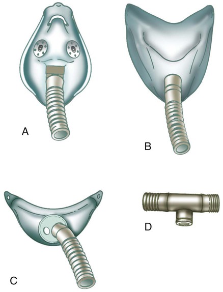
Airway Appliances
Airway appliances used to deliver bland aerosol therapy include aerosol mask, face tent, T-tube, and tracheostomy mask (Figure 35-16). The aerosol mask and face tent are used for patients with intact upper airways. The T-tube is used for patients who are orally or nasally intubated or who have a tracheostomy. The tracheostomy mask is used only for patients who have a tracheostomy. In all cases, large bore tubing is required to minimize flow resistance and prevent occlusion by condensate.
Enclosures (Mist Tents and Hoods)
Infants and small children may not readily tolerate direct airway appliances such as masks, so enclosures such as mist tents and aerosol hoods are used to deliver bland aerosol therapy to these patients. More recent studies have shown that aerosol hoods can provide aerosol delivery with similar efficiency to a properly fitted aerosol mask in infants, with less discomfort for the patient.53
Sputum Induction
As a diagnostic procedure, sputum induction (Box 35-5) warrants separate attention from other modes of bland aerosol therapy. Over the years, sputum induction has proved a useful, cost-effective, and safe method for diagnosing tuberculosis, pneumocystis pneumonia (caused by Pneumocystis jiroveci [formerly Pneumocystis carinii]), and lung cancer.54–56
Box 35-5 outlines a procedure for sputum induction using a 3% saline solution.57 To ensure a good sputum sample, every effort must be made to separate saliva from true respiratory tract secretions.56 In some cases, protocols include having patients brush their teeth and tongue surface thoroughly and rinse their mouths before sputum induction. Although the distinction between saliva and sputum can be made in the diagnostic laboratory, care during the collection procedure eliminates the need for repeat inductions.
Problem Solving and Troubleshooting
Cross Contamination
Rigorous adherence to the infection control guidelines detailed in Chapter 4, especially guidelines covering solutions and equipment processing, should help minimize the cross contamination and infection risks involved in using these systems. In addition, the water should be changed regularly, and the couplant compartments and nebulizer chambers of USNs should be disinfected or replaced regularly.
Environmental Exposure
Environmental safety issues from secondhand and exhaled aerosol arise mainly when aerosol therapy is prescribed for immunosuppressed patients or for patients with tuberculosis. A survey suggested that RTs may be at increased risk for developing asthma-like symptoms, attributed partly to secondhand exposure to aerosols such as ribavirin or albuterol.58 To minimize problems in this area, all clinicians should strictly follow U.S. Centers for Disease Control and Prevention standards and airborne precautions, including precautions specified for control of exposure to tuberculosis (see Chapter 4). Additional methods for dealing with environmental control of drug aerosols are described in Chapter 36.
Bronchospasm
Even bland water aerosols can cause bronchospasm in some patients. Ultrasonic nebulization of distilled water is used in some pulmonary function laboratories to provoke bronchospasm and to assess bronchial hyperactivity.57 To avoid this problem at the bedside, the clinician should always carefully review the patient’s history and diagnosis before administering any bland aerosol, especially a hypotonic water solution. As indicated in the AARC practice guideline (see Clinical Practice Guideline 35-2), patients receiving continuous bland aerosol therapy should be initially monitored carefully (including breath sounds and subjective response) and reevaluated every 8 hours or with any change in clinical condition.49 If bronchospasm occurs during therapy, treatment must be stopped immediately, O2 must be provided, and appropriate bronchodilator therapy should be initiated as soon as possible. If the physician still requests bland aerosol therapy for such a patient, pretreatment with a bronchodilator may be needed. In addition, isotonic solutions (0.9% saline) may be better tolerated by these patients than water.
Selecting The Appropriate Therapy
Figure 35-17 provides a basic algorithm for selecting or recommending the appropriate therapy to condition a patient’s inspired gas. Key considerations include (1) gas flow, (2) presence or absence of an artificial tracheal airway, (3) character of the pulmonary secretions, (4) need for and expected duration of mechanical ventilation, and (5) contraindications to using an HME.
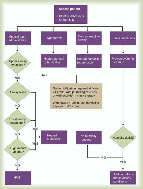
Regarding delivery of O2 to the upper airway, the American College of Chest Physicians advises against using a bubble humidifier at flow O2 rates of 4 L/min or less.59 For the occasional patient who complains of nasal dryness or irritation when receiving low-flow O2, a humidifier should be added to the delivery system. Conversely, the relative inefficiency of unheated bubble humidifiers means that the clinician may need to consider heated humidification for patients receiving long-term O2 at high flow rates (>10 L/min without air entrainment).
HMEs provide an inexpensive alternative to heated humidifiers when used for ventilation of patients who do not have complex humidification needs. However, passive HMEs may not provide sufficient heat or humidification for long-term management of certain patients. When an HME is to be used, it should be selected based on individual patient need and ventilatory pattern and the unit’s performance, efficiency, and size. All patients using HMEs should be reevaluated regularly to confirm the appropriateness of continued use.60
Mini Clini
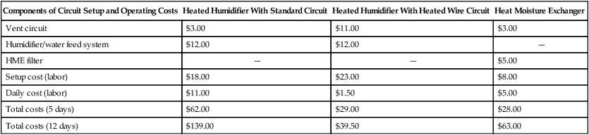
Cost-Effectiveness of Humidification Systems
 Problem