[level-membership-for-physical-medicine-and-rehabilitation-category]
35 Epidural Steroid Injections
Cervical, Thoracic, and Lumbar: Transforaminal, Interlaminar, and Caudal
History
There is a report in English literature that refers to the caudal injection approach for pain management in 1930.1 The first recorded use of corticosteroids injected into the epidural space for the treatment of “sciatica” was in 1952.2 The route of administration was one of the dorsal foramina of the sacrum, an early, blind, transforaminal technique. This technique was employed in Europe in the 1950s and 60s.3
Interlaminar approaches to the lumbar epidural space were reported in the 1960s.4–6 Caudal and interlaminar techniques became standard practice in the United States, Britain, and most of continental Europe for the next quarter century. Interest in the transforaminal approach reemerged in the last quarter of the 20th century, in an attempt to deliver more target-specific injections.7–9 The cervical literature is sparse by comparison to that of the lumbar spine. The interlaminar approach for epidural injections was generally used in the 1980s.10–12 Cervical transforaminal injection was first reported in 1988.13 A descriptive outcome study by Bush and Hillier employing this approach followed in 1996.14 The transforaminal approach was adopted to deliver therapeutic agents to more specific targets influenced by observations that lumbar transforaminal injections appeared to be effective in treating lumbar radicular pain.15,16
There are few reports of the origin of thoracic epidural steroid injections (ESIs) for treatment of spinal pain.17,18 A specific technique for thoracic transforaminal epidural injection was described in 2001.19
A recent systematic review revealed an increase in the number of lumbosacral spine injection procedures performed in the last decade of the twentieth century. There was an increase of more than 270% noted between 1994 and 2001.20 Forty percent of these procedures were associated with the diagnosis codes for “sciatica,” “radiculopathy” or “herniated disc.” “Axial low back pain” diagnoses accounted for 36% and “spinal stenosis” 23%. A study of the Medicare population between 1993 and 1999 revealed that the annual number of cervical, thoracic, and lumbar epidural steroid injections peaked at more than 680,000 in 1998.21 These studies focused on the Medicare population, but it is likely that similar increases would be found for the general adult pain population.
A review of conservative care for sciatica published in 2000 surveyed 19 randomized controlled trials and pooled odds ratios calculated for several treatment types. The data indicated, “Epidural steroids may be beneficial for subgroups of nerve root compression.”22
In 2009, Lavin published results of an extensive MEDLINE/PubMed search and searches of large review articles on the major interventional spine topics. This review was performed to find all prospective, double-blind, randomized, placebo-controlled trials in the English language interventional spine literature. He concluded “Fluoroscopically guided lumbosacral transforaminal epidural corticosteroid injections are effective in the treatment of acute/subacute lumbosacral radicular pain, and in preventing future surgeries. No firm conclusions were drawn about cervical epidural (CESI) injections or lumbosacral epidural (LESI) injections for the treatment of chronic radicular pain.23 A study of the American Society of Anesthesiologists (ASA) Closed Claims Project database revealed that epidural steroid injections account for more complications than any other interventional pain procedure.24
Relevant Anatomy
The spinal epidural space is a continuous potential space in the vertebral canal extending from the foramen magnum to the sacral hiatus, lying between the dural sac and the osseoligamentous wall of the vertebral canal. The epidural space is bounded posteriorly by the lamina and ligamentum flavum. The anterior boundary is formed by the posterior disc margin, the posterior longitudinal ligament and the peridural membrane. This membrane attached to the upper and lower ring apophysis of each vertebra, blends with the disc annulus. It spans the waist of the vertebral body.25 Together these tissues form the floor of the vertebral canal. The lateral boundary of the epidural space is fenestrated by paired root canals or foramina at each segment. The vertebral pedicles lie between the root canals.
The dural sac nearly fills the vertebral canal and extends from the foramen magnum terminating in the sacral canal at the level of the S1 to S2 segments. There is some variability and the thecal sac may terminate as high as the lumbosacral interspace or may extend to S3. At each vertebral segment paired dural root sleeves extend toward the root canals. The cervical and thoracic dural root sleeves are short and nearly horizontal in orientation, traversing the center of their respective root canals. The lumbar root sleeves are longer, increasing slightly in length and downward angle from L1 to the sacrum. Lumbar root sleeves turn laterally into grooves in the vertebral bodies and pedicles and are in intimate proximity to the medial/inferior border of the pedicles. This is the entrance zone of the root canal, or lateral recess of the vertebral canal. The dural root sleeve contains the dorsal and ventral rootlets of the segmental nerve. The dorsal ganglia lie generally in the midzone of the root canals, between the pedicles of adjacent vertebra. The dura and arachnoid membranes form a “water-tight” seal at the proximal end of the ganglia. Cerebrospinal fluid (CSF) fills the root sleeve but does not extend beyond the ganglia. Occasionally ectasia of a dural root sleeve will occur, resulting in extension of the subarachnoid space beyond usual boundaries. Referred to as cystic root sleeve dilatation or Tarlov cysts, they usually communicate freely with the subarachnoid space.26 They may occur at any level of the spine but are most frequent in the sacral region. Usually asymptomatic, they are rarely associated with symptoms.27
There are accumulations of fat in the posterior vertebral canal, deep to the ligamentum flavum and posterior to the dural sac in the thoracic and lumbar spine.28 This posterior fat pad may be small or absent at the L5-S1 level when the dural sac is full size and is applied close to the lamina and ligamentum flavum, as it frequently is. Additional accumulations of fat are found laterally at the level of the discs within the root canals. There is little fat in the cervical epidural space. Midline sagittal spin echo (SE) T1 images of the spine demonstrate the lumbar and thoracic fat pads quite well. Fat is rarely visualized in the vertebral canal above the C7-T1 level. Ample fat fills the vertebral canal below the termination of the dural sac in the sacral vertebral canal.
A thin anterior membrane extends from the posterior longitudinal ligament to the anterior surface of the dural sac. This ventral meningovertebral ligament forms a nearly continuous septum, that functionally divides the ventral epidural space into left and right compartments in the lumbar region.29 A midline dorsal connective tissue band fixes the dural sac to the flaval ligaments. The appearance of the band varies from strands of connective tissue to a complete membrane.30
A plexus of valveless veins occupies the anterior epidural space.31 Paired anterior internal epidural veins run the length of the vertebral canal. There are numerous interconnecting veins crossing the floor of the canal, the anterior internal vertebral venous plexus (AIVV).32 A smaller posterior internal venous plexus lines the roof of the epidural space in the lumbar and thoracic regions. Extending laterally around the vertebra, the peridural membrane encloses veins that course around the body of the vertebra.25 These veins communicate freely with the basivertebral veins, at the center of the posterior wall of each vertebral body and the anterior internal vertebral venous plexus. Several radicular veins traverse each root canal. They lie predominantly in the ventral root canal and connect the epidural venous plexus with the ascending lumbar veins and the vena cava.
Segmental arteries traverse the root canals at all spinal levels.33 They course in the anterior superior root canals along the anterior superior aspect of the segmental dural root sleeve. Some arterial branches perfuse the dorsal ganglia and segmental neural elements and, as such, are radicular arteries. Other branches penetrate the dura running along the segmental rootlets and may anastomose with the anterior spinal artery. They are, therefore, medullary arteries. Varying numbers of medullary arteries of differing sizes are found in the cervical, thoracic, and lumbar region, and contribute to the blood supply of the spinal cord.
The radicular and medullary arteries of the cervical spine arise primarily from the vertebral artery.34,35 Some arise from the ascending cervical and posterior cervical arteries. Medullary arteries penetrate the dura and divide into anterior and posterior branches, eventually reaching the anterior and paired posterior spinal arteries. Cervical medullary arteries are variable in size and distribution. There are usually two or three arteries of moderate size in the adult. They may be present at any segment and on either side.36,37
The upper and midthoracic cord is supplied by medullary arteries arising from branches of the costocervical trunk and spinal branches of the aorta. There is usually a single large medullary artery arising from the aorta and supplying blood to the lower half of the thoracic cord and conus. This large medullary artery, the artery of Adamkiewicz, has a variable origin but usually originates on the left side (80% of patients), between T7 to L4, most often between T9 and T11.38 In a study of 4000 spinal cord angiograms, there were three instances in which the major medullary artery of the distal thoracic cord originated at the fourth lumbar artery.39
Paired lumbar arteries originate from the aorta at each lumbar segment. These give rise to spinal branches that include radicular and medullary branches.40 Most lumbar spinal branches are small. Some may be 1.0 to 2.0 mm in diameter. There is potential for a medullary artery of substantial size to be present in any root canal.41
Spondylogenic Pain
Spondylogenic pain arises from a component of the spine or its supporting structures, and is synonymous with other terms such as nonspecific or idiopathic spinal pain. The International Association for Study of Pain (IASP) published a taxonomy, defining clinical terms used to describe pain, in an effort to standardize the use of terms.42
Somatic pain results from noxious stimulation of a musculoskeletal component of the body and arises as a result of stimulation of nociceptive nerve endings in bone, ligament, joint, muscle or tendon. Visceral pain occurs with noxious stimulation of a body organ or its capsule. Both somatic and visceral derangements cause pain in the location of the source structure, but it is often vague and ill defined.
Radicular pain occurs when there is irritation or injury of a spinal nerve or its roots. In the lumbar spine, simple compression of a normal nerve or nerve root does not provoke pain.43 Alone, pressure on a spinal nerve or its roots may produce a conduction block of axons. Sensory axon conduction block results in loss of sensation or “numbness.” Motor axon block results in weakness. Compression alone can result in radiculopathy, without radicular pain. Pressure on a previously injured or damaged nerve or root provokes pain. Local ischemia or inflammation can induce ectopic impulses in a dorsal root canal ganglion resulting in radicular pain. Lumbar radicular pain is discretely localized, “bandlike” in distribution, and shooting, lancinating, or shocking in quality44 and can have a cutaneous component.
Preprocedure Evaluation
Spine imaging plays a definite role in the evaluation of spine pain complaints both in demonstrating relevant pathology and aiding in planning a safe and efficient approach for procedures. Modern imaging modalities provide excellent depictions of spine anatomy. However, many lesions, evident in the maturing spine, are clinically insignificant.45 Imaging studies often demonstrate pathology that is irrelevant. Computed tomography (CT) or magnetic resonance imaging (MRI) may demonstrate a left C3-4 disc protrusion in a patient complaining of right arm pain and altered sensation radiating to the right forearm, thumb, and index finger. It cannot be overstated that there is a significant incidence of pathology in asymptomatic subjects.46 A focal disc protrusion on the right at L3-4 may be clearly defined by MRI, in a patient complaining of left buttock pain extending to the left calf.47 Scans should be reviewed overall, but with particular attention to areas that might be related to the patient’s underlying complaints, as gleaned from the interview and examination. One should carefully study the left L4-5 and L5-S1 root canals in a patient with pain extending from the left buttock to the left anterolateral leg and dorsum of the foot. Recently 150 patients with unilateral leg pain, and MRI confirming neural compression by prolapsed disc or foraminal stenosis had lumbar transforaminal epidural injections (LTFE) at appropriate sites. These were effective in relieving their pain initially, and only18% of these patients required surgery at a minimum 1-year follow up.48 Not all abnormalities need be targeted but rather those most likely to be associated with the expressed symptoms and physical findings.
Absolute contraindications include active psychosis and homicidal or suicidal ideation. Studies have shown a relationship between physical and sexual abuse and various types of pain. Correlation of failed low back surgery with childhood trauma has revealed definite risk factors. These include physical, psychological, and/or sexual abuse, emotional neglect, abandonment, and chemical dependence and/or loss of a primary caregiver.49–51 Relative contraindications include personality disorders, bi-polar disorder, severe depression, lack of social support, and drug dependence/abuse.
A Few Medical Issues
Contrast Material
Allergic reactions to modern contrast materials are extremely rare. Some may be related to preservatives such as methylparaben. Wang reviewed 84,928 intravenous contrast injections noting “allergic” reactions in 545 (0.6%).52 Seventy seven percent of the reactions were “mild,” primarily urticaria, successfully treated with diphenhydramine. Twenty one percent had moderate reactions with respiratory symptoms, facial edema, or both. Corticosteroids intravenously or by inhaler were effective in controlling these reactions. Two percent, eight women and three men, had severe reactions (0.0012%). Three were unresponsive; frank cardiorespiratory arrest occurred in one. There were no deaths and no long-term sequelae in 10 of the 11 patients with severe reactions.
Contrast material is employed to document where the injectate is spreading and to determine where it is not spreading. Modern nonionic contrast agents are safe for all epidural injections. Unintentional vascular or even subarachnoid spread will cause no problem. In those very rare instances of documented history of severe allergic reaction to nonionic contrast material, gadolinium may be employed as a substitute radiography contrast agent.53
Diabetics taking metformin are at risk for contrast material nephropathy (CMN) if exposed to nonionic contrast material, during radiographic procedures. Solomon found no change in renal function in those subjects who had normal renal function prior to testing.54 However, some patients with normal renal function exhibited increases of serum creatinine with high-contrast loads.55 This should not be a problem with epidural injections because the contrast doses employed are limited and much lower than the volumes delivered in the radiologic procedures. Doses in excess of 100 mL are not unusual for enhanced CT or angiograms. However, diabetic patients with renal impairment should discontinue metformin, with approval of their primary physician.
Local Anesthetics
The local anesthetics employed in the epidural injections are lidocaine and bupivacaine. These amides are primarily metabolized in the liver and excreted in the urine. Their allergic potential is extremely low. Ester-based local anesthetics (procaine) have a higher incidence of allergic reaction. A large survey attests to the overall safety of the amides as spinal anesthetics.56 For epidural injections, lidocaine may be employed in concentrations of 0.5% to 4.0% and bupivacaine at 0.25% to 0.75%. The percentage concentration of the anesthetic is reduced with increasing volume delivered. Although central nervous system and cardiovascular system toxicity can occur following the epidural, intravenous, or subarachnoid injection of local anesthetics, the toxic doses are far greater than the volumes employed in epidural injections—40 mL of 1.0% lidocaine (400 mg) delivered to the epidural space of test subjects resulted in average peak plasma concentrations safely below neurotoxic levels.57 One author recommended the maximum epidural dose of lidocaine to be 500 mg and 225 mg for bupivacaine.58
Acute cardiac complications, decreased cardiac output being one, can occur from intravascular injection of lidocaine or bupivacaine. Study has shown that normal cardiac function is maintained in subjects with lidocaine plasma levels of 4 to 8 mcg/mL. Plasma levels this high require doses of >400 mg of lidocaine.59 In human volunteers slow intravenous (IV) injection of bupivacaine to produce plasma concentrations equivalent to those achieved during epidural injections did not cause significant cardiovascular change.60 Between 3.0 and 7.0 mL of low concentrations of anesthetics for interlaminar injections and 0.75 to 2.0 mL of higher concentrations for transforaminal injections are not toxic in the epidural space. These doses are not toxic if technical misadventure results in delivery to the vascular system or subarachnoid space. Because of the longer half-life of bupivacaine, this anesthetic should be avoided in interlaminar epidural injections, particularly in the cervical spine. Inadvertent delivery into the subarachnoid or subdural space results in prolonged effects, specifically affecting respiratory function with misplaced cervical injection. Decreased concentration of anesthetics must be considered for interlaminar epidural injections in the cervical and thoracic regions in patients with respiratory or cardiovascular health problems because decreased cardiac output and heart rate can occur with sympathetic blockade, which occurs to some degree with all interlaminar epidural injections.
Corticosteroids
In the central nervous system, nerve tissues exhibit increased excitability, EEG abnormalities are seen, subjects experience euphoria and behavioral changes. Rarely, these effects can be severe. A case report describes 67-year-old male who developed psychotic episodes within a week of a cervical ESI, along with other steroid injections in one treatment session. The symptoms spontaneously resolved in approximately 7 to 10 days.61 This case serves to remind us that we must always be cognizant of the doses we deliver, and remember patients may be receiving “steroid shots” from other physicians for unrelated problems.
Endocrine system alterations include decreased adrenocorticotropic hormone (ACTH), thyroid-stimulating hormone (TSH), and follicle-stimulating hormore (FSH), and testosterone. The changes are largely dose related. Bizarre responses do occur rarely. A 24-year-old man underwent a second cervical ESI of 60 mg of methylprednisolone for ongoing severe arm pain. A cushingoid appearance developed 1 month later. Serum cortisol was undetectable, there was no adrenal response to synthetic ACTH, and urinary-free cortisol was below normal at 12 weeks. Cortisol normalized in 4 months, however, the patient’s cushingoid appearance persisted for 12 months.62
An epidural steroid injection of 160 mg of methylprednisolone will suppress adrenal function for weeks.63 Does injection of corticosteroids increase the risk of infection? Infections do occur in patients following ESIs.64 Postoperative infections are increased in hip replacement patients who received preoperative steroid injections.65 No studies have been done on outcomes of spine surgery after ESI, but suppression of the immune system suggests there is inherent risk, especially in the first 4 weeks post injection.
Epidural administration of glucocorticoids results in potent suppression of insulin action. This should be taken into account when patients with diabetes receive ESIs.66 Lumbosacral transforaminal and caudal epidural betamethasone injections are associated with statistically significant elevations in blood glucose levels in diabetic subjects. This effect peaks on the day of the injection and lasts approximately 2 days.67 The administration of three epidural injections (250 mg prednisone equivalent) was followed by suppression of the corticotropic axis that persisted beyond 21 days. Plasma cortisol and ACTH and urinary free cortisol were markedly reduced at the day 1 and day 7 posttreatment visits, compared to baseline. At 21 days, these variables were still diminished.68 We must be vigilant in follow-up of our diabetic patients.
The musculoskeletal system suffers from some bone mineral density loss, muscle weakness and wasting, and predisposition toward avascular necrosis with long-term oral steroid use. Although systemic corticosteroids may be associated with loss of bone mineral density, a prospective study of 204 patients followed for 1 year after standard doses of epidural steroids revealed no change in bone mineral density.69
The currently used steroids contain preservatives. Bernat thought that seizures following intrathecal cortisone acetate were due to the preservative, 0.9% benzyl alcohol. Benzyl alcohol is common in depot steroids and is neurotoxic.70 Hodgson reported that there was no concrete evidence of neurotoxicity of intrathecal steroids, but did not recommend purposeful delivery of these agents into the subarachnoid space.56
Major Complications
Infection
Infection following epidural injection is a serious issue. It has been described as a rare complication.71 However, the possibility of procedure-related infection must be a concern for the injectionist. Analysis of the American Society of Anesthesiologists (ASA) Closed Claims database from 1970 to 1999 revealed that infection was the third most common complication of chronic pain procedures, accounting for 13% of all complications.24 Any penetration of the skin surface with a needle then placed in deep spaces in and about the spine has the potential of introducing organisms with subsequent infection.72 Standard aseptic preparation and draping of the local injection site and good aseptic technique will minimize this complication. Diabetic and immunocompromised patients are a subgroup that should be recognized prior to procedures. Antibiotic prophylaxis should be considered for immunocompromised patients undergoing ESI.73 Antibiotics should not be mixed with the contrast during any epidural injection. Accidental delivery of antibiotics into the subarachnoid space must be avoided.
Bleeding/Hematoma
Many veins lie in the needle path or near endpoint targets of transforaminal epidural injections (TFESI). Furman and colleagues reported the incidence of fluoroscopically confirmed “vascular uptake” occurring during lumbar74 and cervical75 transforaminal injections. Observing blood at the needle hub reliably predicts intravascular injection, (97% specific). But this finding has low sensitivity, (45% overall). The absence of blood in the needle hub despite aspiration is not reliable. The incidence of vascular uptake with lumbar procedures is about 11%. There is a higher incidence in the cervical spine where confirmed intravascular injection was observed in nearly 20% of patients. Kim and coworkers have recently reported a much higher rate of vascular uptake for cervical transforaminal injections, more than 50%.76 Although neither author specified, most of the vascular uptake seemed to be venous. No complications occurred. Venous uptake during epidural injections is common and innocuous as long as it is recognized and needle adjustment is made before injecting physiologic solutions. Veins are less abundant in the posterior epidural space and venous uptake is less frequently seen during interlaminar epidural injections.
Three surveys of cervical interlaminar epidural injection on more than 2200 patients claim no major complications.76–78 Minor adverse responses, such as increased headache, insomnia, vasovagal episodes, facial flushing, dural puncture, and short-term nocturnal fever were encountered. Similar response profiles occur with thoracic79 and lumbar interlaminar injections and caudal epidurals as well. Most of these are likely a response to the corticosteroid and are unavoidable for the most part.
The incidence of epidural hematoma is approximated to be less than 1 in 150,000 epidural injections.80 Clinically relevant hematoma may occur at any level, the majority of reported cases were associated with injections in the cervicothoracic area. Spinal epidural hematoma causing acute myelopathy is a rare complication. In a case report, Stoll and colleagues noted epidural hematoma after ESI in a young man with no predisposing factors.81 An older patient with apparently normal coagulation received multiple cervical ESIs for palliative pain control over several years. A hematoma that required surgical decompression occurred following the seventh procedure.82
The potential for bleeding and hematoma formation is increased in patients with a coagulopathy, liver disease, or in patients taking anticoagulant medications. It is crucial that the injectionist be familiar with a patient’s coagulation status and with common anticoagulant and antiplatelet medications.83 Anticoagulant therapy should not be interrupted until there is full understanding of the reason for the therapy. Actual discontinuation of anticoagulant therapy is usually best left to the physician managing and prescribing the patient’s anticoagulation. Epidural injections are elective procedures. Interrupting anticoagulant therapy may increase the risk of serious complications such as stroke, myocardial infarct, or pulmonary embolus.
The following guidelines for performing spinal procedures in anticoagulated patients are based on the second American Society of Regional Anesthesia and Pain Medicine (ASRA) Consensus Conference on Neuraxial Anesthesia and Anticoagulation in 2003.80 Warfarin therapy should be discontinued 4 to 5 days before spinal procedures and the international normalized ratio (INR) should be within normal range at the time of the procedure. Thienopyridine derivatives, (e.g., clopidogrel, ticlopidine) should be suspended 7 days and 14 days, respectively, prior to spinal procedures to allow for recovery of primary and secondary platelet aggregation and platelet-fibrinogen binding.
Dural Puncture
During interlaminar epidural injections, the dural sac is at risk. Transforaminal injections place the dural root sleeves at risk. Nonfluoroscopically guided interlaminar injections have increased incidence of dural puncture with prevalence up to 5.0% in cervical epidural injections.84 Dural puncture is reportedly rare when the procedure is performed by “expert” interventionalists.85 Minor complications, including headache secondary to dural puncture occurred in less than 0.5% in more than 4300 procedures. Dural puncture may occur with more frequency in the cervical spine above C7 and at L5-S1. In both areas there may be a paucity of epidural fat with the dural sac juxtaposed against the flaval ligament. Failure to recognize subarachnoid spread results in injection of anesthetic and steroid into the subarachnoid or subdural space. Delivery of anesthetics in sufficient quantity and concentration may produce significant spinal block, most serious at cervical levels where the block may impair respiration. These misadventures are avoided by selection of appropriate target, proper needle, good visualization, a cooperative, comfortable—but minimally sedated—patient and precise technique.
Spinal Cord Puncture
Minimal direct cord injury occurs if there is puncture of the spinal cord. Injection of any solution into the substance of the cord is a major problem. Injury is proportionate to the volume of injectate. Direct puncture of the cord provokes pain and altered sensation in most subjects. Injection of solution into the substance of the cord adds to the trauma with ischemic pressure injury at the site of the injection in the cord. Hodges reported two cases of cervical cord injury secondary to cord injection. Both patients were heavily sedated an unable to respond.86 Severe thoracic cord injury occurred when a low thoracic epidural injection was performed under general anesthesia.87 Some cord punctures may not provoke pain.88 Mayall reported permanent paraplegia resulting from multiple attempts at thoracic epidural injection in an awake patient. No lateral view was used during the procedure.89 Surgery subsequently revealed multiple punctures of the cord. These complications are technical misadventures. They are minimized by careful attention and precise technique.
Brain and Spinal Cord Infarct
Arterial filling during transforaminal injections has been rarely reported. Only two cases of cervical medullary artery filling during transforaminal injection have been reported.90,91 In both instances medullary artery filling was recognized during real time fluoroscopy and confirmed, in one instance, with digital subtraction angiography (DSA). Both procedures were aborted without further incident. A single case of lumbar radicular/medullary artery filling during transforaminal injection has been published.92 Filling of a small artery in the central canal during a right S1 transforaminal injection was recognized during real time fluoroscopy, but demonstrated more dramatically with DSA.
Transforaminal injections are hazardous because of important arterial structures in the target field. Delivery of a particulate steroid into an artery may result in embolization of particles, larger than capillaries, with subsequent ischemia and/or infarct of the perfused tissue. There were nonpublished, anecdotal reports of catastrophic neurologic complications associated with epidural injections circulating during the last decade. Brouwers and colleagues reported the first such occurrence in 2001.93 The central cervical spinal cord infarct occurred in conjunction with a fluoroscopically guided C6 transforaminal injection. This was likely the result of embolization of the anterior spinal artery watershed by way of a reinforcing cervical medullary artery.37
The next year Houten and colleagues reported the first cases of lower thoracic and conus infarct occurring as a result of lumbar transforaminal injections.94 Two injections were performed at the L3-4 level, one on the left, the other on the right. The third was an injection at S1. The authors implied probable injection into an aberrant artery of Adamkiewicz.
A more likely hypothesis is injection into lumbar or sacral radiculomedullary arteries. In 1971, Lazorthes reported observing a well-developed anastomotic circulation to the conus and distal thoracic cord by way of lumbar and sacral arteries. In an experimental study, colloid material was injected into the aortic circulation, below the origin of the artery of Adamkiewicz and was subsequently identified in the distal cord and conus of the experimental animals.41 He postulated that these colloid emboli reached the anterior spinal artery circulation by way of reinforcing lumbar and sacral radiculomedullary arteries.
Glaser reported paraplegia following a thoracolumbar transforaminal injection in 2005.95 Yin and Bogduk reported retrograde flow in a radicular arterial branch and subsequent filling of the thoracic anterior spinal artery. Retrograde flow into medullary arteries or the vertebral artery without direct cannulation can occur, providing an alternative mechanism of potential injury to the spinal cord or brain during transforaminal injections.96
Since the first report in 2001, there has been a frightening number of case reports of catastrophic neurologic complications in the literature.97 In a mail-in survey, Scanlon collected 287 responses from physician members of American Pain Society. There were 78 major neurologic complications associated with cervical TFE. All procedures involved injection of particulate steroid preparations. There were vertebrobasilar brain infarcts and cervical spinal cord infarcts.
The survey did not explore thoracic spinal cord and conus infarcts. There are more events than case reports; many are encountered in the context of medicolegal proceedings.92 One of the authors (CA) has reviewed six distal thoracic/conus infarcts in the last 2 years, none of which has been reported in the literature. Kennedy and colleagues reported two cases of distal thoracic cord and conus infarcts that occurred in conjunction with L3 TFE injections. A left L3 TFE was performed with fluoroscopic guidance, using betamethasone (Celestone) as injectate. A right L3 TFE was performed with CT guidance, using methylprednisolone acetate (Depo-Medrol). Paraplegia occurred almost immediately in both cases. Follow-up MRI scans demonstrated typical distal thoracic spinal cord and conus infarcts, with increased signal intensity in the central cord from about T9 to the tip of the conus.98 Prevention of these complications begins with awareness that this can happen.
First, recognize intraarterial injection when it occurs.91 Careful real time fluoroscopy, in the frontal plane, during slow injection of an adequate volume of contrast to opacify vessels is mandated. Visualization of vessels can be enhanced by DSA.
Second, injection of a small test dose of concentrated local anesthetic before injecting steroids, especially with particulate varieties, to test for onset of neurologic signs may allow recognition of unexpected flow in the vertebral or medullary arteries.99
Currently the presumed mechanism of spinal cord injury is an embolic shower of particles of the steroid preparation into the circulation of the anterior spinal artery.100,101 A third safety measure is to avoid particulate steroids entirely for all transforaminal epidural injections.
Dexamethasone sodium phosphate is a nonparticulate steroid. Derby and associates found the particle size in this preparation to be approximately 10 times smaller than red blood cells and they do not appear to aggregate. They have lower density than the particles and aggregates of methylprednisolone acetate, triamcinolone acetonide, and betamethasone sodium phosphate/acetate, the most commonly used agents.100 In a comparison study, Dreyfuss and colleagues reported that dexamethasone was slightly less effective than triamcinolone, but the difference was not statistically significant.102 There have been no reported infarcts when dexamethasone has been used for transforaminal injections. Two animal studies have demonstrated severe neurologic injury to the animals when particulate steroid preparations were injected into the carotid103 and vertebral104 arteries. There was no evident injury to the animals receiving intraarterial injections of the nonparticulate preparation, dexamethasone. A theoretically safer nonparticulate agent appears to be a valid alternative to the particulate agents that have been used to date.
Epidural Injection Techniques
Equipment
Fluoroscopy
Fluoroscopy is mandated for all interventional spinal procedures, including injections performed for the diagnosis or treatment of pain of spinal origin. Although “blind,” nonfluoroscopically guided, interlaminar injections for peri- and postoperative analgesia are the norm in the anesthesia arena, the specialty of interventional pain or non-surgical spine, demands precise needle placement, selective administration of medications, validation of the procedure, and a historical record. The literature105–107documents that in experienced hands, successful epidural needle placement is to be expected in only 60% to 70% of cases where fluoroscopy is not used. A 30% to 40% failure rate does not provide a sufficient probability of success on which to base a diagnostic or therapeutic modality. Therefore, interventional spinal pain procedures performed using nonfluoroscopically guided (i.e., blind) techniques should be considered as highly inappropriate and possibly sham, and fraudulent procedures whether being performed for diagnostic or therapeutic objectives. Rationalizations that the cost of fluoroscopy is prohibitive, equipment unavailable, historical precedent, or the “vast experience and skill” of the practitioner, usually belies economic impairment or poor, insufficient training and cannot be used as an excuse for the substandard practice of medicine.
It is imperative that all physicians performing fluoroscopically guided spinal injections have training in the interpretation of real time fluoroscopic images whether cervical, thoracic, lumbar, or sacral. This training must be beyond the level of a residency and most current “pain” fellowships. Expertise in radiologic interpretation is far beyond the training and proficiency of nurse anesthetists (CRNAs), physician assistants (PAs), and other so-called “mid level nonphysician providers.” Performance of interventional pain procedures constitutes the practice of medicine as noted by at least one judicial body within the United States,108 and numerous medical specialty societies including the American Medical Association,109 the International Spine Intervention Society,110 and the American Society of Anesthesiologists.111
Regarding radiographic guidance, although the use of CT guidance has been advocated by a small minority of radiologists,112 most radiologists within the interventional pain community reject the use of this imaging modality for the placement and validation of safe needle position. Using CT allows one to accurately delineate the skin entry point; however, the advancement of the needle toward the target is accomplished crudely, without imaging assistance. This adds to the physical discomfort of the patient, the time required to complete the procedure, and the chance for needle misadventures. CT necessitates the injection of contrast for verification of needle placement without the benefit of active, real time imaging. Vascular injections will, in all likelihood, escape detection owing to the rapid “washout” of contrast secondary to blood flow within the vein or artery. In addition, the marked increase in total radiation exposure to the patient, as inherent in CT, should be of concern. No literature exists in which evidence indicates any benefit to the use of CT for routine spinal injections. Specialty group guidelines published by the International Spine Intervention Society (ISIS)113 and the Physiatric Association of Spine, Sports, and Occupational Rehabilitation (PASSOR),114 specifically do not mention CT use for epidural injections, whether transforaminal or interlaminar. As noted previously, severe permanent neurologic sequelae following the use of CT for cervical and lumbar transforaminal epidural injections have been reported in the literature and medical legal documents. These cases involved paraplegia, quadriplegia, and death secondary to cord infarct.
Miscellaneous Supplies
A variety of needles and syringes are required and these vary according to the specific procedure intended. For interlaminar injections, prepared trays offered by a number of companies are often the most efficient, and cost effective, option. Hustead, Crawford, or Tuohy epidural needles of 18 or 20 gauge, 3.5-inch are ideal for most situations. Occasionally a 5-inch needle is required. Interlaminar injections require the use of tactile sense by tissue resistance for realization of needle tip position during needle insertion. This ability to identify needle tip position by feel is lost when smaller gauge needles, 22 or 25 gauge, are used and will result in a higher incidence of dural puncture. In addition, the valuable identification with aspiration of CSF with intrathecal placement, or blood when intravascular, cannot be relied on if these needlessly small needles are used. The adequate use of local anesthetic renders the insertion of an 18 gauge needle no less comfortable than the use of a smaller gauge instrument. Sharp, cutting needles designed for intrathecal placement, Chiba or Quincke type, were not designed for use in accessing the epidural space via the interlaminar approach because the variation of resistance of the tissue layers trespassed cannot be as readily appreciated. A 5 mL loss of resistance (LOR), glass or plastic syringe is unique to the interlaminar approach. Injections into the most caudal aspect of the epidural space through the sacral hiatus can, in most instances, be undertaken with a 25-gauge 1.5-inch needle.
Transforaminal epidural injections are best accomplished with 25-or 22-gauge needles. In nearly all cases, 3.5- or 5-inch lengths suffice. Quincke or Chiba beveled needles are used by the majority of experienced practitioners. A small bend of the tip, opposite the bevel, is used by experienced physicians to allow precise directional control during insertion. Occasionally, an intertransverse fusion mass may prevent the direct insertion to the target. This might require the use of a two needle technique: an introducer needle of larger diameter, (18 gauge) placed at the correct target depth, and a procedure needle with a large bend capable of maximum lateral movement, inserted through the introducer. Although some practitioners have advocated the use of blunt needles to prevent unintentional arterial uptake, no evidence exists as to this claim as has been addressed in detail.115 In addition, blunt needles require an introducer needle to puncture the skin, are difficult to control, and (in at least one small study) have been shown not to decrease the incidence of vascular puncture.116
Medications
Although there are a number of corticosteroids that have been used epidurally by interventional pain physicians for more than 50 years, none have been approved for intraspinal use by the United States Food and Drug Administration (FDA). All corticosteroids must, therefore, be described as “off label.” Methylprednisolone, betamethasone, triamcinolone, and dexamethasone have all been advocated. Of the aforementioned corticosteroids, the first three are suspensions, only dexamethasone is a solution that is commercially available.117 Regarding transforaminal injections, there appears to be correlation between the use of particulates and spinal cord and brain infarctions owing to arterial occlusion. Therefore, for cervical, thoracic, or lumbar injections into the intervertebral foramen, the solution, dexamethasone, would appear to offer a real safety benefit.
Although emergent situations are rare during the practice of interventional pain procedures, vigilance and preparedness are essential. One never knows when a situation requiring immediate intervention will occur. Physicians performing spinal injections must be proficient in emergency protocols including airway management and cardiovascular resuscitation. A basic course such as Advanced Cardiac Life Support (ACLS) should be considered a minimum requirement. In addition, well-trained, and practiced, procedure room personnel who are able to assist the physician and monitor the patient provide a safeguard to ensure immediate and appropriate patient care, should the unexpected occur. Whether the procedure is performed in an office, ambulatory surgery center, or hospital setting, emergency equipment, pharmaceuticals, oxygen, airway supplies, suction, and other resuscitation provisions must be immediately available and checked regularly to ensure proper function.
Intravenous Access
IV access should not be considered mandatory for routine injections of steroid into the epidural space, be it cervical, thoracic, lumbar, or sacral. Although some medical facilities mandate an IV, and at least one well respected guideline concerning spinal injections (ISIS) recommends the practice for transforaminal injections,118 it should not be considered standard of care. Although complications requiring the use of IV medications, (allergic reactions, severe vasovagal reactions, high intrathecal-spinal anesthetic block) are exceedingly rare, the high cost and risk/benefit ratio make routine intravenous cannulation questionable. Of course, use of sedation requires intravenous access.
Periprocedure Techniques
Caudal Needle Placement
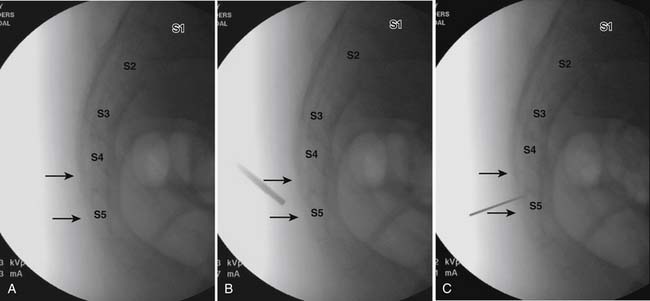
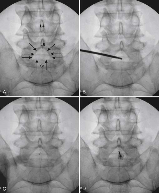
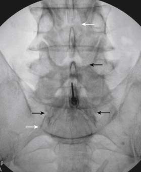
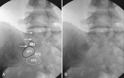
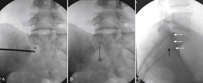
The patient is placed in the prone position (often a pillow under the hips provides increased access). Rotating the feet so that the toes are pointed medially and the heels lateral will relax the gluteal muscles and facilitate access to the entry point. In obese patients with large buttocks and a deep gluteal cleft, 3-inch surgical tape can be used to pull the buttocks apart and allow access to the needle insertion area over, or somewhat caudal, to the sacral cornu. The skin over the sacral hiatus, including the lower lumbar and sacral areas, is prepared and draped sterilely. The fluoroscope is positioned in lateral view because the sacral hiatus is usually quite difficult to identify using an anteroposterior (AP) fluoroscopic orientation. In a lateral view, the sacral lamina can be seen to extend down to S4 with an abrupt drop off noted identifying the sacral hiatus (Fig. 35-1, A). A metal pointer is positioned in the midline, over or slightly caudal to the sacral hiatus (see Fig. 35-1, B) and a 25-gauge needle is inserted (see Fig. 35-1, C). Anatomy allows the use of a 1.5-inch needle in the majority of cases. The needle will be felt to puncture the sacral coccygeal ligament and contact with os will be noted at the dorsal aspect of the S4 vertebral body in the ventral caudal canal. If the injectionist desires to advance the needle cephalad, a slightly more caudal insertion might be used. In this case, the needle can be advanced up the caudal canal to the level of S3—the level to which the dura extends in most individuals.
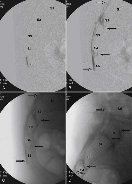
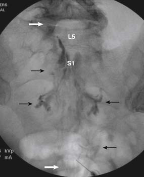
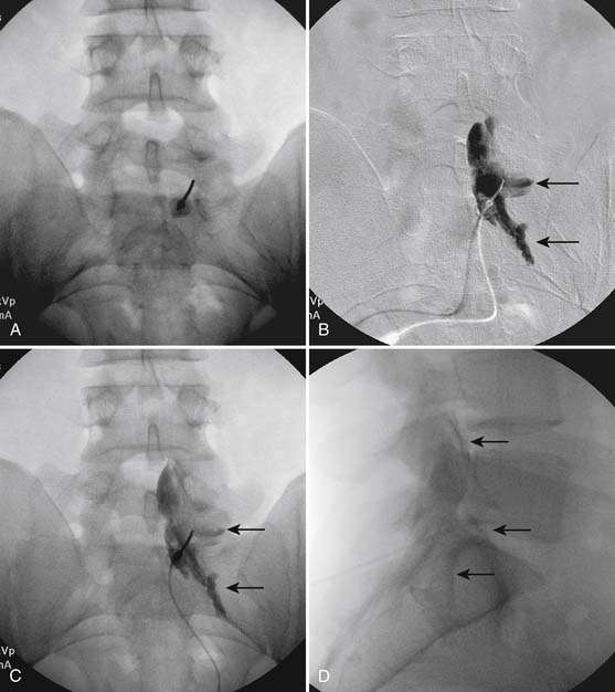
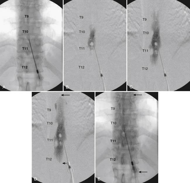
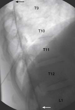
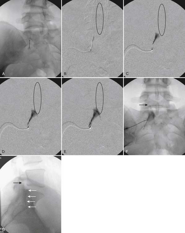
When the needle is in position, contrast is injected under real time fluoroscopy. DSI (Fig. 35-2, A and B) often provides a more exact indication of the rostral contrast spread. Ventral flow through the ventral sacral foramen is often seen and can be extensive (see Fig. 35-2, C). Although an AP image is often obtained, the flow of contrast is usually better appreciated in the lateral view as is unintentional dural puncture. If appropriate spread of contrast is appreciated, the corticosteroid preparation with normal saline, 3 to 5 mL total is injected. Three milliliters of injectate will reach the L5-S1 disc level in approximately 80% of the injections (see Fig. 35-2, D). Larger volumes provide little added benefit. The extra epidural flow, as noted earlier, can severely limit the volume of active injectate actually reaching the pain generator (Fig. 35-3). Images documenting needle position prior to injection, and verifying contrast pattern and extent of coverage, must be saved for the medical record.
Lumbar Interlaminar
Because lumbar interlaminar (i.e., between the lamina) epidural injections place the active injectate closer to the area of pathology, they must be considered somewhat more selective than caudal administration of corticosteroids. These injections are often mislabeled as “translaminar,” that is, through the lamina. The needle is placed into the epidural space via a posterior approach, through the interlaminar space, and ligamentum flavum, but stopped prior to dural puncture. Injection is made into the dorsal epidural space (Fig. 35-4).
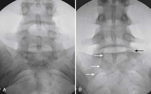
Following appropriate positioning, the lumbosacral region is prepared and draped sterilely. The fluoroscope is used to examine the lumbar spine. Segmental anomalies such as sacralized L5 vertebral bodies, or nonsacralization of S1 should be noted and detailed on the procedure note. The targeted interlaminar space is then identified in an AP view (Fig. 35-5, A) caudal to the pathology unless a far lateral needle placement is contemplated. Because the majority of pathology is seen in the two lower lumbar levels, the L5-S1 and L4-5 interlaminar spaces are the most frequent targets. Cephalocaudal tilt results in the interlaminar space being seen at its maximum size, whereas a slight ipsilateral oblique view often provides easier access. When adequate visualization is obtained, the skin over the target is marked (see Fig. 35-5, B). Local anesthetic can then be injected (see Fig. 35-5, C) and the epidural procedure needle advanced. At this point, tactile feel is of utmost importance and can only be taught using “hands on” instruction in living subjects. The needle is felt to transverse through the various tissue layers until a midprocedure position is noted; resistance to needle advancement is noted secondary to contact with the ligamentum flavum (see Figs. 35-5, D and Fig. 35-6, A). Although some experienced practitioners make a point of contacting os on the superior aspect of the lamina caudal to the targeted space, the feel of contact with ligamentum flavum, is as distinct as this boney target. If contact with bone was sought, and contact was made, the needle is slightly withdrawn, redirected, and advanced until the distinct resistance of ligamentum flavum is noted. At times, insistence on contacting os prevents targeting a specific area of the interlaminar space. If os is not touched, the ligamentum flavum is engaged directly. Using a loss of resistance (LOR) technique with either constant pressure on the plunger of a glass/plastic LOR syringe with normal saline or short interval, light intermittent pressure with an air-filled LOR syringe, the needle is advanced. A very obvious loss of resistance to the saline or air is noted as the needle aperture exits the ventral aspect of the ligamentum flavum and enters the epidural space. At the present time, hanging drop and Macintosh balloons must be considered passé and of historical interest only. A lateral view can now be used to indicate needle depth (see Fig. 35-6, B) if necessary. However, if the needle is not placed in the exact midline, or a “true lateral” is not used, depth as noted by visual clues can be faulty due to the tangential imaging. No specific bony landmarks are available to verify needle tip entry into the epidural space. Special care must be taken when working above the L2-3 level because the spinal cord must be considered.
Aspiration, at this point, should evidence no or very minimal, clear or lightly blood-tinged fluid. As noted earlier, with the use of small needles, CSF return is not a reliable indicator of intrathecal needle placement. Images to document placement in AP, and possibly lateral views are obtained (see Figs. 35-6, B and 35-7, A). Injection of contrast, under active fluoroscopy in AP view is now performed to ensure needle position by contrast pattern (see Fig. 35-7, B-F). A nonhomogeneous, vacuolated pattern is apparent with epidural injection versus the homogeneous pattern noted with injection into the CSF. Although an AP view may make noting an intrathecal injection difficult, vascular uptake will be obvious because these structures are perpendicular to the needle, and visualization is transient owing to flow within the structure. A lateral view is now used to rule out intrathecal or subdural patterns and verify epidural spread of contrast in the dorsal epidural space (Fig. 35-8). Subdural injections between the dural and arachnoid layers will be cystic with clearly delineated margins. Subarachnoid injections of contrast in the lateral view will layer out in the ventral intrathecal space because it is heavier than CSF. Subdural injections mandate withdrawal of the needle dorsal to the liga-mentum flavum and reinserting toward a different target with LOR once again appreciated. If dural puncture is noted with an intrathecal pattern, the procedure can be attempted at an adjacent level or abandoned for that day.
After validation of epidural injection is obtained and images are saved, the physician can now proceed with the injection of corticosteroid in a total volume of 2 to 4 mL. Larger volumes will result in wider dispersion of a less concentrated mixture, neither of which factors is beneficial if a specific pathology has been targeted. A so-called “washout” or postinjection film can be saved to document final dispersion of material within the epidural space (Fig. 35-9).
Because one is often treating a unilateral, or one side dominant, pain complaint, one of the authors (ML) targets the side of pathology/symptomatology. Fig. 35-10) illustrates this alternative approach where flow into the ventral epidural space and segmental nerve canals is routinely observed with a proposed increase in efficacy.
Thoracic Interlaminar
The thoracic interlaminar technique involves additional risks because the spinal cord lies millimeters ventral to the ligamentum flavum. In addition, the dorsal epidural space is narrower than in the lumbar region (Fig. 35-11). This procedure should not be attempted by any physician who has not had extensive training and experience working in the lumbar region.
As with all interlaminar injections, the patient is best placed in a prone position and an appropriate sterile preparation of the skin and draping at the proposed skin entry site are completed. Because the lamina of the thoracic spine resemble overlapping shingles on a roof, excellent visualization of the interlaminar space is often impossible. Anatomically, the interlaminar space will always be found ventral to the spinous process of the rostral level. Using the fluoroscope, the targeted interlaminar space is identified and optimum visualization is obtained using cephalocaudal tilt of the image intensifier (Fig. 35-12, A). A paramedical approach is advocated because the orientation of the lamina and spinous process often makes a midline approach difficult, especially if any degree of rotoscoliosis is present. This becomes quite evident in the midthoracic region, T4-10.
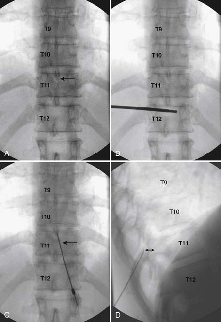
Using an AP orientation with caudal tilt of the image intensifier, the skin entry point is marked, slightly more than one level below the target and lateral to midline (see Fig. 35-12, B). Therefore if the T10-11 interspace is targeted, the skin entry would be over the T12 lamina. A local anesthetic track toward the lamina above is completed to a depth of ~1.5 inches. The epidural needle is advanced toward the targeted midline interlaminar space and os is contacted over the lamina (T11) of the vertebra just caudal and lateral to the target (see Fig. 35-12, C). The needle is then slightly withdrawn and advanced slowly toward the spinous process rostral to the target (T10). The distinctive resistance of the ligamentum flavum will be noted and advancement of the needle is halted. A lateral view may be obtained at this point and the needle tip will be noted lying dorsal to the epidural space. Using the LOR technique as described earlier, the needle is advanced slowly through the ligamentum flavum.
It is important to realize that the anatomy of the thoracic spine differs from that of the lumbar spine in that the transverse processes angle to a greater extent dorsally, and the superior articular processes (SAP) lie ventral to their anatomic position in the lumbar spine. The needle, when within the dorsal thoracic epidural space, will appear dorsal to the lamina and SAP (see Fig. 35-12, D). Images precontrast, AP, and lateral, to document needle position are archived. After negative aspiration for CSF and blood, contrast is injected and flow is verified in the dorsal epidural space (Figs. 35-13 and 35-14). Because of the narrowness of the epidural space in the thoracic spine, spread of a small volume of contrast can be extensive with 2 to 3 mL covering greater than five levels with flow to the ventral spinal canal being minimal (see Fig. 35-14).
Cervical Interlaminar
Interlaminar injections may appear elementary in the hands of an expert, but significant morbidity and mortality has occurred when the inexperienced injectionist has not heeded the aforementioned advice. Access to the cervical epidural space via the transflaval approach can be accomplished safely if quality instruction is received, proper technique is used, care and vigilance is practiced, and significant, extensive experience at other levels is obtained prior to attempt of this seemingly easy procedure. The cervical epidural space is narrow, 3 to 5 mm, and the tactile clues differ significantly from the lumbar or thoracic levels. The anatomy is unique especially in regard to the dorsal angle of the laminae, presenting imaging uncertainty when assessing depth within the central canal. In patients with short necks or large body habitus the shoulders may prevent adequate lateral visualization at C7-T1 or even C6-7. In addition to the anatomic variation, knowing that only millimeters separates an injection into the dorsal epidural space from penetration of, and injection into the spinal cord, creates an apprehension knowing that death or quadriplegia can easily result from a slight needle misadventure.
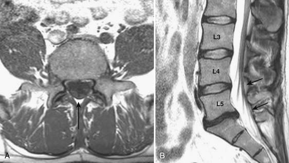
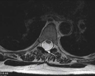
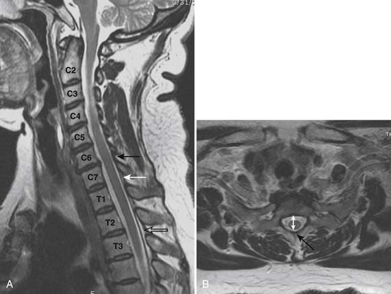
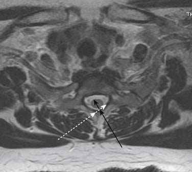
Prior to any placement of a needle into the cervical canal, a recent high quality MRI or CT scan must be evaluated by the physician planning the injection (Fig. 35-15). Canal diameter must be assessed prior to the injection to ensure adequate space within the epidural space. The epidural space must be assessed to see if an interlaminar injection can be performed safely. The normal diameter of the spinal canal is 12.5 mm or greater, with a cord diameter of ~9 mm. Cerebral spinal fluid (CSF) should be identified surrounding the cord on axial views. An AP diameter of less than 11 mm is considered to be relative spinal stenosis, whether congenital (i.e., owing to short pedicles) or secondary to acquired pathology (i.e., disc protrusion or spondylosis). An AP diameter of less than 10 mm is significant and placement of a needle at any level with this degree of compromise, is questionable, especially if no epidural fat is noted dorsally on imaging.
Because the dorsal epidural space thins markedly above C6, interlaminar injections above the C6-7 level are never appropriate and pose an undue risk to the patient. Dr. Richard Derby, an outstanding, experienced, and well known interventional pain physician from an anesthesia background, stated that, “a cervical epidural injection rarely should be performed above C7-T1.”119 Because the most common levels of pathology occur at C5-6 or C6-7, this makes the C7-T1 interlaminar spaces ideal to target. If pathology, anatomy, or postsurgical changes necessitate, the T1-2 interlaminar space can be chosen. In a series of patients by one of the authors (CA), CT scan approximately 15 minutes post-interlaminar injection, using small volumes at the lower cervicothoracic junction, has shown contrast covering the entire cervical epidural space. Therefore, precision of level might be a moot point and of little significance regarding cervical interlaminar injections.
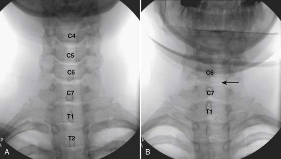
The patient is placed in the prone position with the neck slightly flexed. The posterior upper dorsal and cervical regions are prepped and draped in a sterile manner. The AP fluoroscopic view is obtained (Fig. 35-16, A) and the targeted interlaminar space identified. Using cephalocaudal tilt, the image intensifier is positioned to maximize the interlaminar space (see Fig. 35-16, B).
In most cases, a slight paramedian approach provides the easiest access, and a slight ipsilateral oblique view may be helpful. Some practitioners advocate a midline approach, perpendicular to the ligamentum flavum and the dorsal dura. However, the feel of the needle contacting and traversing the ligamentum flavum is an important technical aspect of this procedure. Because the resistance noted by contact with the ligamentum flavum is correlated to the distance traversed through it, this resistance is increased when entering at any decreasing angle from perpendicular to this structure. In addition, needle contact with the dura at a 90-degree angle is more apt to result in trespass into the intrathecal space, with subarachnoid injection, or cord penetration. Dural contact at a less acute angle would be expected to distort or “tent” the dura without penetration, with fewer expected cases of intrathecal encroachment. The LOR technique with saline will increase this “dural tenting” because a low-volume stream of pressurized saline will be injected into the potential epidural space before extensive needle entry, distorting the dura and providing some additional space and margin of safety. Therefore, a paramedian approach (Fig. 35-17) with a LOR technique with saline, might be considered a safer alternative.
Using the paramedian approach, a point on the skin is marked lateral to midline over the superior lamina of the level below (Fig. 35-18, A) and local anesthetic is injected (see Fig. 35-18, B). Care must be used because the average depth from skin to epidural space at C6-7 and C7-T1 is 57 mm (2.25 inches) and 54 mm (2.12 inches) at T1-2120, in an exceedingly slender person a 1.5 inch needle might be long enough to reach the spinal canal with intrathecal injection of local anesthetic resulting in a “high spinal block,” or spinal cord injection. The epidural needle is then advanced through the anesthetized tissue toward one of two endpoints. Many practitioners advocate contact with the most rostral aspect of the lamina to provide a reliable measure of depth (see Fig. 35-18, C). However, if this bony contact cue is missed due to imaging uncertainty or inexperience, the injectionist while expecting this firm contact with os, might unknowlingly advance the needle through the ligamentum flavum, dura, and into the spinal cord. When os is contacted, a lateral view can be obtained and depth can be verified as dorsal to the spinolaminar line. The needle is then slightly withdrawn, redirected to slide off os, and the ligamentum flavum is contacted. A more experienced physician, who has gained a tactile sense of the needle passing through distinctive tissue layers, may omit the touching of the lamina and advance the needle directly toward the interlaminar space until the distinct feel of the ligamentum flavum is noted.
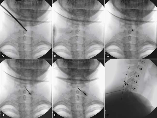
Figure 35-18 A-D, Slight ipsilateral oblique view cervical spine. C6-7 interlaminar space maximized. A, Pointer on skin over target indicating rostral aspect of the C7 lamina caudal and slightly lateral to interlaminar space. B, Needle placement for local anesthetic injection. C, Epidural needle advanced and touching lamina below and lateral to interlaminar space target. D, Needle through ligamentum flavum, verified by loss of resistance to saline and air. Negative aspiration for cerebrospinal fluid (CSF) and blood. E, AP view cervical spine. Needle in epidural space at dorsal midline. F, Not true lateral view cervical spine. Note margins of neural arch not aligned (arrows). Needle appears somewhat ventral to spinolaminar line (broken line) due to suboptimal imaging. Compare to Figure 35-21, A.
When the ligamentum flavum is contacted, the LOR syringe is attached and the needle is slowly advanced until loss of resistance with saline or air, as described earlier, is noted (see Fig. 35-18, D). A quasi feel of loss of resistance is often present in the cervical spine as the needle transverses the tissue between the interspinous ligament and ligamentum flavum, and only experience may be able to differentiate this from the “true” loss of resistance as one enters the epidural space. In addition, a false loss of resistance can also be appreciated when in close proximity to periosteum prior to the tactile sensation of laminar os being contacted. When the needle has traversed the ligamentum flavum and is in the epidural space (see Fig. 35-18, E) aspiration should be negative for CSF and blood. If CSF is noted, the needle must be withdrawn and either epidural placement attempted at a different level or, possibly a better option, the procedure discontinued and the patient discharged to return at a future date. If frank blood is noted, the needle is withdrawn dorsal to the ligamentum flavum is redirected, and loss of resistance is once again sought at a slightly different area.
Although a true lateral view with identification of the needle at the spinolaminar line has been advocated to verify depth prior to injection of contrast, this technique can be fraught with misleading information (see Fig. 35-18, F). A single lateral view is not sufficient to gauge depth because the laminae in the cervical spine are not orthogonal, perpendicular to the x-ray beam; they slope at approximately 45 degrees (see Fig. 35-19). Lateral images are further distorted secondary to the displacement of the needle tip from midline. For every aberration, the lateral image becomes progressively less valid. To exactly calculate needle tip position, the AP view provides information about the rostral-caudal and medial-lateral placement, whereas a tangential image through the lamina opposite which the tip of the needle lies (i.e., the contralateral oblique view) delineates needle depth—although being dependent on the precise degree of obliquity can be deceptive as to the reality of needle tip position. Exact knowledge of needle placement requires tactile clues as to tissues penetrated, multiple fluoroscopic views, and the training, experience, and expertise to evaluate each unique situation. Unlike many other injections, two views, AP and lateral, do not always provide sufficient information to accurately place the tip of the needle in a safe position. All images indicating that the needle is in a safe final position, prior to contrast injection, are archived.
When access to the epidural space is evidenced through the use of LOR and possibly by imaging, contrast is injected under active fluoroscopy (see Figs. 35-20 to 35-23) in a volume that will ensure that the injection is being made within the epidural space, and that intrathecal, subdural, and vascular flow are absent. A volume of 2 to 3 mL is usually adequate. Images of contrast verifying safe needle position and appropriate contrast flow are saved for the historical record. Verification of needle position with contrast is followed by injection of the active pharmaceutical compound, corticosteroid. Diluents of either normal saline or low concentration local anesthetic can be used safely with the understanding that neither has a therapeutic or diagnostic role and local anesthetic can be assumed to have a higher morbidity profile.
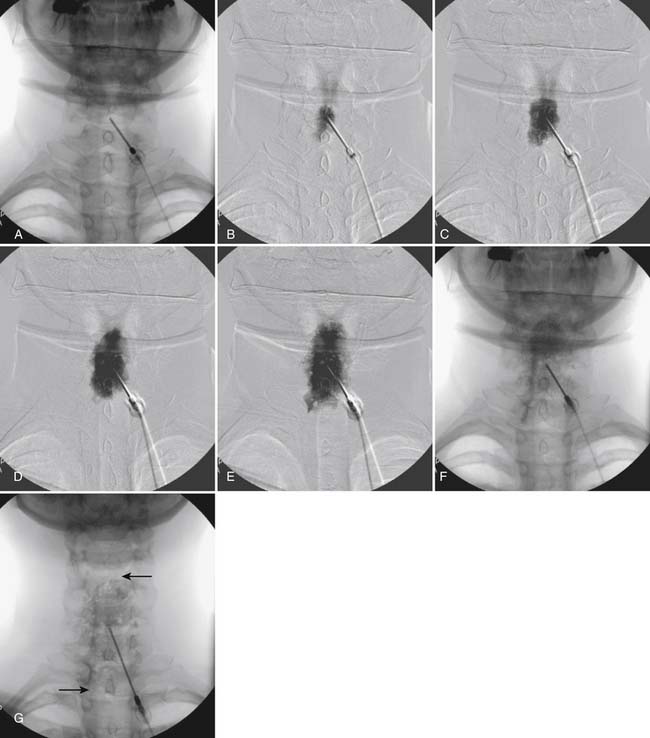
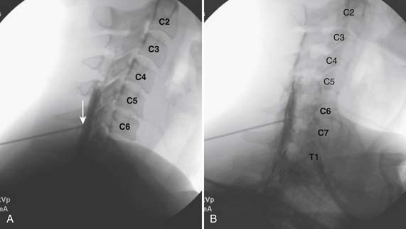
Figure 35-21 A,True lateral view cervical spine. Compare with figure 35-18, F. Note needle tip at spinolaminar line (arrow). Image at end of contrast injection, ~2.5 mL. Note nonhomogeneous vacuolated pattern at spinolaminar line consistent with dorsal epidural injection. Spread of contrast is seen ventrally and extends rostral to C4-5. B, Oblique view cervical. Note needle tip at spinolaminar line. Image at end of contrast injection, ~2.5 mL. Note nonhomogeneous vacuolated pattern at spinolaminar line consistent with dorsal epidural injection. This view is often required when body habitus prevents adequate lateral imaging of the lower cervical levels.
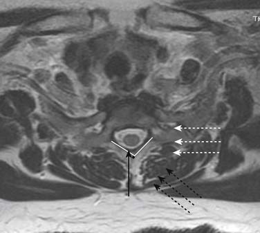
As in the lumbar region, the patients chief complaint, and index pain is often unilateral or one-side dominant. Again, one of the authors (ML) feels compelled to target the side of pathology/symptomatology, especially when as noted, a less than perpendicular approach to the epidural space may provide a margin of safety as the anatomy in Figure 35-17 indicates. Figs. 35-22 and 35-23illustrate this alternative approach where flow into the ventral epidural space and segmental nerve canals is routinely observed with a theoretical increase in efficacy.
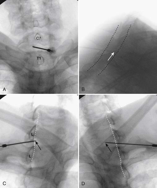
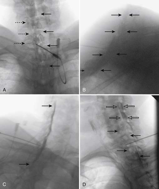
Figure 35-23 Cervical spine after injection of contrast, ~2.5 mL, at C7-T1. A, AP view. Note essentially unilateral, vacuolated contrast pattern extending from C5 to T2. Flow of contrast into spinal nerve canals is present (broken arrows). Compare to Figure 35-22, AB, Lateral view. Suboptimal image secondary to patient body habitus. Note wide contrast column, not confined to the dorsal epidural space, indicating spread of contrast into the lateral and ventral epidural space covering the proposed pathology. Compare to Figure 35-22, BC, Right oblique view (i.e., contralateral to needle tip position). Note contrast clearly in the dorsal epidural space ventral to the spino-laminar line. Compare to Figure 35-22, CD, Left oblique view (i.e., ipsilateral to needle tip). Note marked vacuolated epidural pattern (solid arrows). When the image is corrected for obliquity, the tubular structure, indicated by open arrows, would be situated over left uncinate line and is consistent with spread of contrast around the vertebral artery, indicating that the injectate is covering the ventral lateral recess, vertebral foramen, and neural contents. Compare to Figure 35-22, D.
During injection, it is common for the patient to note some neck pain as well as transient, mild pressure paresthesia into the upper extremity, in addition to a feeling of “warmth” and “pressure,” in the chest. These symptoms do not necessitate discontinuing the injection unless they are severe.
S1 Transforaminal Corticosteroid Injection Technique
Of the lumbar intervertebral discs, L5-S1 is the second most common to suffer from protrusion, or extrusion, often with S1 segmental nerve involvement. Therefore, instillation of corticosteroid around the S1 DRG is a procedure frequently employed by the interventional pain physician and constitutes one of the core procedures of our specialty. This injection requires placing a needle through the dorsal foramen of S1, thereby accessing the S1 nerve canal.
The patient is placed in a prone position. The lower lumbar and sacral areas are prepared and draped as detailed previously. Using an AP view, the fluoroscope is oriented to identify the area just caudal to the S1 pedicle on the symptomatic side (Fig. 35-24, A). The superior end plate of S1 is squared (see Fig. 35-24, B) and a slight ipsilateral obliquity is used until the dorsal foramen is visualized directly caudal to the S1 pedicle and medial to the lateral wall of the S1 nerve canal (Fig. 35-24). The target should be seen as distinct from and slightly rostral to the larger, and often more obvious, S1 ventral foramen (see Fig. 35-25, A and B).
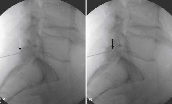
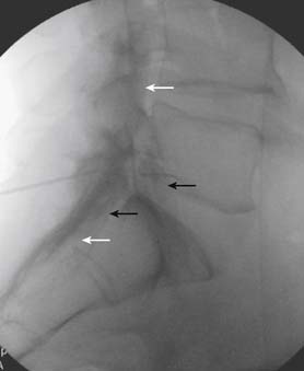
The skin entry point is marked over, or just caudal to the target, Fig. 35-26, A, and if desired local anesthetic injected. A 25- or 22-gauge spinal needle is then advanced toward the lateral-caudal aspect of the foramen (Fig. 35-26, B), just medial to the lateral nerve canal wall in that the course of the S1 segmental nerve is medial (see Fig. 35-26, B). Slight reduction in resistance to needle insertion will be felt as the needle enters the foramen. As the needle is advanced, it may contact the lateral wall of the nerve canal or the dorsal aspect of the S1 vertebral body (i.e., the ventral canal). The bent needle technique will allow continued precise advancement. A lateral view is used to note appropriate depth with the needle tip lying between the lamina and anterior canal (see Fig. 35-26, C). At this point, AP and lateral images are saved for the permanent medical record to document needle position prior to injection of contrast.
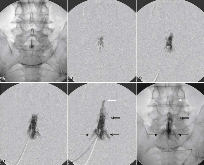
Using an AP view, contrast is injected slowly under active fluoroscopy, with DSI if available (Fig. 35-27, A-F). The contrast should be flow proximally toward the L5-S1 intervertebral disc without significant vascular uptake. Although medullary arteries are not seen at this level,121 retrograde venous filling toward the conus might be appreciated and would necessitate repositioning of the needle. If the majority of contrast is noted to travel distally through the ventral foramen, the needle should be repositioned until contrast is covers the targeted structure. A lateral view then demonstrates filling of the S1 nerve canal with minimal contrast flowing out of the ventral foramen (see Fig. 35-27, G).
Lumbar Transforaminal
Injection into the lumbar intervertebral foramen with corticosteroid for radicular pain is of known therapeutic value. Because the L4-5 intervertebral disc is most susceptible to injury, the most common level for this procedure is the L5-S1 foramen, covering the L5 dorsal root ganglion and segmental nerve. Segmental anomalies of sacralized L5 or nonsacralized S1 vertebral bodies occur in approximately 15% of patients, and care must be taken to ensure the correct level is being injected. The targeted foramen can be identified in an AP image by being bounded in a cephalocaudal orientation by the pedicle above and below, and medial to lateral by the medial and lateral pedicular lines. For the majority of cases, positioning of the needle in a subpedicular position, and in the middle foramen in the dorsal-ventral orientation, is safe, and distances the needle tip from the possible position of the medullary artery (i.e., artery of Adamkiewicz, as discussed earlier). A so-called “retroneural” positioning of the needle has been described122; however, this technique can be considered a slight variant of the standard technique. Occasionally, because of marked degenerative changes, no access to the foramen is available via the subpedicular approach. In this case, an alternative infraneural technique can be used that targets the caudal ventral aspect of the foramen, and will be described following the standard approach.
The patient is placed in prone position with a pillow under the lower abdomen to decrease the lumbar lordotic curve. After a sterile preparation and draping of the skin at the injection site, the fluoroscope is positioned to obtain an AP view with the pedicle shadow bounding the upper aspect of the targeted foramen, in the center of the fluoroscope monitor (Fig. 35-28, A). As in the majority of spinal injections, to obtain a true AP image, cephalocaudal tilt of the image intensifier is used so that the vertebral end plate closest to the target is “squared,” (i.e., the x-ray beam is parallel to the end plate, which appears as a solid line rather than an ovoid structure). In the case of an L5-S1 transforaminal injection this would be the inferior end plate of L5 (see Fig. 35-28, B), for an L4-5 transforaminal injection the inferior end plate of L4, and so on.
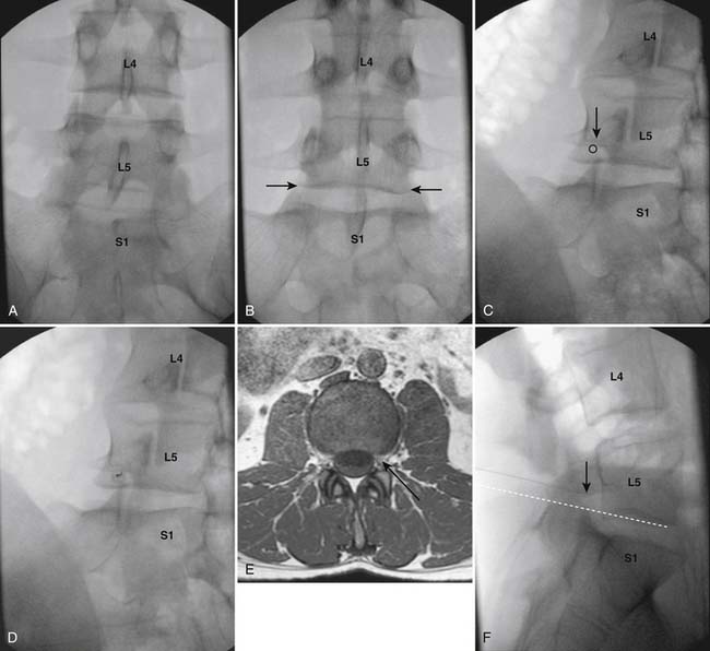
Figure 35-28 AP image at lumbosacral junction. A, Note the superior end plate of S1 is not parallel to the x-ray beam. B, Inferior end plate of L5, closest to target, is parallel to x-ray beam indicating a true AP view. C, Left oblique view. Note that the SAP of S1 appears to lie under the 6:00 o’clock position of the L5 pedicle. Circle represents needle target. D, Left oblique view. A 25-gauge, 3.5-inch Quincke pointed spinal needle is seen having been advanced into the L5-S1 foramen caudal to the 6:00 o’clock position on the pedicle. E, MRI subpedicular axial L4-5 T1 WI. Representation of needle insertion into the left midforamen. F, Lateral view of the lumbosacral junction. The tip of the 25-gauge, 3.5-inch spinal needle is seen in a subpedicular position in the midsection of the L5-S1 foramen. Broken white line indicates needle was inserted parallel to the inferior end plate of L5, showing correct initial AP positioning of the C-arm (see Fig. 35-28, B).
An ipsilateral oblique projection is now obtained so that the tip of the superior articular process (SAP) of the level below is positioned under the approximate “6 o’clock” position of the pedicle when seen as a clock face. In the case of the L5-S1 transforaminal injection, the fluoroscope is positioned so that the S1 SAP is seen as positioned under the L5 pedicle (see Fig. 35-28, C). Anatomically, if a needle is now advanced into the subpedicular position, and the tip does not stray medial to the rostral tip of the SAP and 6 o’clock position of the pedicle, the spinal canal is safe from trespass. If desired, a skin wheal can be considered, especially if needles greater than 25 gauge are used. The procedure needle is advanced using a down-the-beam, “tunnel vision,” technique toward the inferior aspect of the pedicle shadow (see Fig. 35-28, D).
In most cases, a needle of 5 inches is needed to enter the L5-S1 foramen due to the greater depth required secondary to the cephalad tilt of the image intensifier, as required to obtain a true AP at this level. As the needle is advanced, the operator needs to be ever conscious of depth—realizing that os will in all probability be contacted, and to prevent further insertion, at one of four structures: the lamina, SAP, transverse process, or vertebral body. If the three former boney structures are contacted, the bent needle can be used to maneuver around them. If the lamina, SAP, and transverse process are passed, tactile clues will indicate passage through the dorsal leaf of the intertransversarii muscles. At this point, a lateral view can be used to verify that the needle has entered the foramen (see Fig. 35-28, F). If the needle is advanced so that the dorsal vertebral body is contacted in the ventral foramen, a lateral view will note this and the needle is withdrawn a few millimeters. An AP view will ensure that the needle has not been excessively advanced medially, past the 6 o’clock position of the pedicle, where entry into the dural root sleeve might be expected (Fig. 35-29, A). Lateral and AP views are saved to document final needle position and provide a permanent record of the procedure (see Figs. 35-28, F and Fig. 35-29, A).
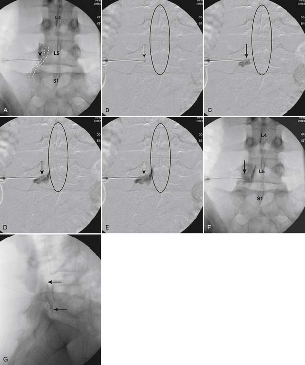
An AP view is now used for injection of contrast under active fluoroscopy because the structures that present danger, the medullary artery or retrograde flow to the conus, are perpendicular to the beam and will be well visualized. DSI can be used if available, and the operator has been trained in its use, but is not considered standard of care at this juncture. Contrast should be seen to flow medially through the foramen into the epidural space (see Fig. 35-29, B-F). Contrast will often be seen following the medial border of the pedicle spreading toward the intervertebral disc at the level above. If the majority of contrast is seen to flow laterally along the ventral ramus, it shows that a significant portion of the injectate will not come in contact with the pathology, and pain generator, one wishes to treat. Repositioning of the needle is then recommended. Minimal venous uptake is not a contradiction to completing the procedure. However, if marked venous flow is seen, this necessitates repositioning of the needle and reevaluation with contrast.
Vascular flow of contrast laterally, or to the contralateral side, can be presumed to be venous, whereas flow to the midline, with or without evidence of cephalad extension, must be considered arterial and the procedure must be terminated. Following verification of a safe contrast pattern with AP imaging, a lateral view (see Fig. 35-29, G) will confirm contrast in the targeted foramen, often with spread in the ventral epidural space to the pedicle above. Lateral and AP images with and without contrast are archived to verify that the procedure has been performed as stated, with technical competence, and as a record for any medical legal questions which might arise at a future date.
As noted earlier, because of anatomic variation, such as severe degenerative disc disease with intervertebral disc narrowing or marked osteophytic lesions, subpedicular access to the foramen may be limited. In this case, an infraneural approach to the foramen over the intervertebral disc might be chosen. The end plates at the specific level are squared to the x-ray beam. An ipsilateral oblique view is then obtained so that the SAP of the level below is situated under the approximate midpoint of the inferior end plate of the level above. After the skin infiltrate of local anesthetic, the procedure needle is advanced toward the intervertebral disc, just lateral to the SAP. This technique is analogous to that used to access the intervertebral disc during discography, with advancement halted within the foramen prior to entering the disc annulus. Resistance will be noted as the annulus is contacted and a lateral view obtained to verify needle depth. (Fig. 35-30, B). The needle will be seen lying in the inferior aspect of the foramen, possibly adjacent to the intervertebral disc. An AP view is checked to ensure the needle is within the foramen in a medial-lateral orientation (see Fig. 35-30, B). When the infraneural technique is used, flow around the pedicle will not be seen in many instances. The contrast will be noted to flow through the foramen and spread within the lateral epidural space both in a rostral and caudal direction (see Fig. 35-30, C-G).
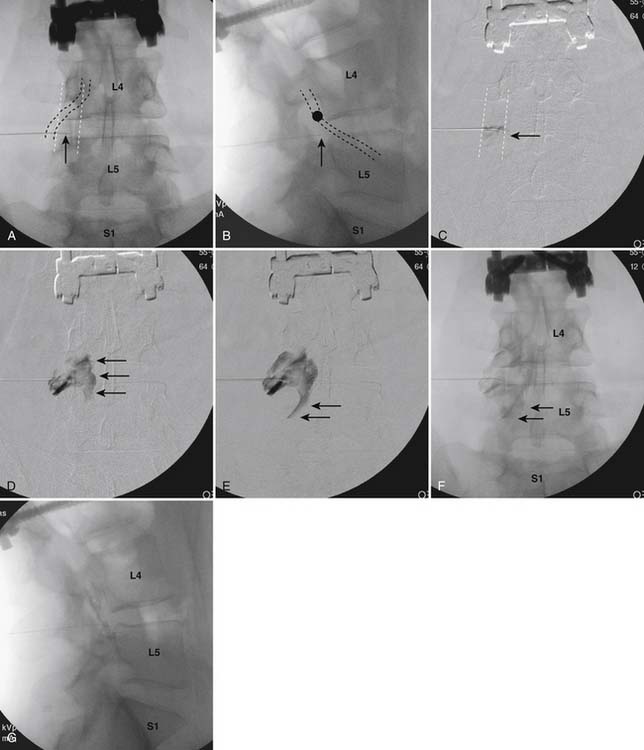
When the injection of contrast produces a satisfactory pattern, the corticosteroid injectate, preferably as a solution, can be injected with confidence that safety is ensured, and the coverage of the pain generator may provide pain relief. Use of 4% lidocaine (Xylocaine) combined with the corticosteroid solution can provide a final concentration that ensures sensory blockade. As noted, this can afford only negative diagnostic information, but is often a worthwhile addition.
As previously noted, some practitioners have advocated the use of a “test dose” of local anesthetic prior to the corticosteroid injection. From a single reported case study,123 it is theorized that if injection into the medullary artery were to occur, local anesthetic would flow into the anterior spinal artery, thereby anesthetizing the spinal cord and producing temporary motor and sensory deficit. The corticosteroid injection would then be abandoned and any detrimental effects of the corticosteroid injection would be prevented. This chain of suppositions depends on the assumption that a solution of corticosteroid injected into the medullary artery will cause a greater deleterious effect to the spinal cord than a solution of local anesthetic. Cord infarctions with the postulated etiology involving injection into the medullary artery, resulting in cord ischemia in the watershed of the anterior spinal artery, have been reported only with the use of particulate corticosteroid preparations. Therefore, if one limits corticosteroid use in transforaminal injections to solutions, this problem should be preventable. In addition, using a test dose 2 minutes prior to injection of the corticosteroid presumes that the needle tip will not move during this period of time: a questionable supposition.
Thoracic Transforaminal Injections
To access the thoracic intervertebral foramina, the patient is placed prone on the procedure table. After a sterile preparation of the skin and draping, the proposed level for injection is identified. Because individual characteristics of the twelve thoracic levels are not easily identifiable (i.e., “all thoracic levels look the same”), it is of utmost importance to be compulsive about ascertaining the correct level. The authors recommend counting down from T1 and marking the skin over the pedicles of the chosen level with a marking pen ensuring that the end plate closest to the target is squared. One then counts up from T12, ensuring that this second enumeration of the specified level matches with the first (Fig. 35-31, A). If any question remains, additional examinations are performed until no doubt exists in the mind of the physician injectionist that the correct level is being targeted.
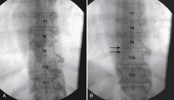
A true AP view is obtained by squaring the inferior end plate of the chosen level; (i.e., T9 if the T9-10 foramen has been chosen to access (see Fig. 35-31, B). The C-arm is rotated in an ipsilateral oblique motion so that the pedicle will appear to move medially toward the midline with the rib head following. The lateral pedicular line, or SAP, is placed between one third and one half the distance over the vertebral body (Fig. 35-32, A). The foramen can be accessed anywhere between the boundary pedicles. Because the medullary artery, artery of Adamkiewicz, is found within the rostral-ventral aspect of the foramen, usually lies caudal to T7, but can be highly variable in location, one of the authors (ML) prefers an infraneural approach, over the intervertebral disc, rather than a subpedicular, needle placement. The target is an area of hyperlucency in the form of a rectangle seen over the intervertebral disc (see Fig. 35-32, B). This so called “magic box” is bounded laterally by a line formed by connecting the medial rib heads; the lateral pedicular line/SAP; and the inferior and superior end plates of the specific level. Local anesthetic can be infiltrated and a 25- or 22-gauge spinal needle can be advanced toward the target using frequent intermittent fluoroscopy (Fig. 35-33, A). As long as the needle is directed medial to the rib head, costovertebral joint, and lateral to the lateral pedicular line, pneumothorax and central canal encroachment is nearly impossible. Often during insertion of the needle, os will be contacted. Because the needle is traversing a space between the proximal rib and SAP, rotation of the bent needle tip will permit continued advancement. Resistance will be noted as the needle contacts the annulus of the intervertebral disc, and further advancement is halted (Fig. 35-33, B and C).
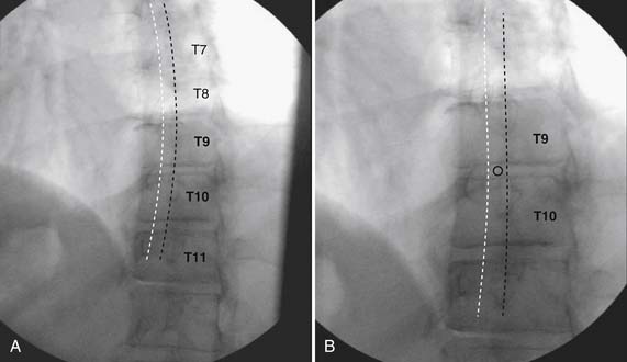
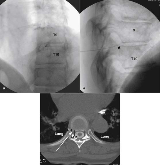
Acceptable needle placement in lateral and AP views is now confirmed and images are saved (see Fig. 35-33, B and Fig. 35-34, A). The needle tip as will be seen in a lateral view as lying in the caudal-ventral foramen, and the AP image will note its foraminal placement between the medial and lateral pedicular lines.
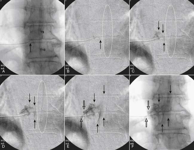
Injection of contrast using active AP fluoroscopy, with DSI if available, will provide confirmation of flow through the foramen into the lateral epidural space without worrisome vascular uptake as detailed previously (see Fig. 35-34, B-F). The lateral view will confirm foraminal and epidural injection (Fig. 35-35).
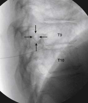
Cervical Transforaminal
As stated previously, in recent years as more physicians with differing levels of training are pursuing interventional pain procedures, a rise in the number of catastrophic outcomes from injection of particulate corticosteroids into the cervical foramen has been realized. This is a procedure that should be shunned by those novices who have not had years of extensive experience and training in regard to the anatomy of the region and correct technique. However, the authors are not aware of any catastrophic events occurring when due diligence was practiced, all images were saved indicating safe needle placement, and a solution injectate was used.
The patient is placed in supine position with a pillow under the shoulders to slightly extend the cervical region. The anterior and procedural side of the cervical region is prepared and draped sterilely. Whereas in most procedures the C-arm fluoroscope is positioned laterally, perpendicular to the patient, some experienced injectionists, including one of the authors (ML), prefer it to be positioned at the head of the procedure table for ease of obtaining views in all planes of projection. This technique lends itself to the operator sitting on the side to be targeted. The C-arm is maneuvered to obtain an oblique view with caudal tilt of the image intensifier, so that the foramina are seen at their widest diameter in respect to both cephalocaudal and ventral-dorsal dimensions. This is the so-called “foraminal” view (Fig. 35-36). In this position, the x-ray beam is focused parallel to the exiting nerve and foramen. An essential understanding of the shape of the foramen is paramount to the safe conduct of this procedure. In this foraminal view, the actual foramen is not an aperture as it appears. In actuality, it is shaped like a funnel (Fig. 35-37) with the central part appearing hyperlucent, whereas the actual outer edge is ill defined and indistinct because it lies over the posterior and anterior boney elements. The target is the SAP of the level below, dorsal to what appears to be the sharp dorsal border of the foramen and approximately one fourth to one third cephalad of the foramen’s most caudal aspect (Fig. 35-38).
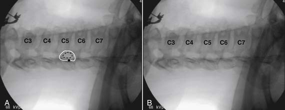
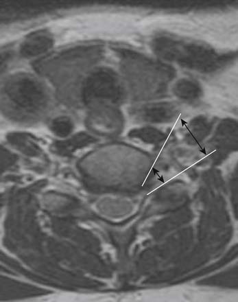
Figure 35-37 MRI axial T2 WI. Shape of cervical foramen seen as “funnel”. Note medial diameter is smaller than lateral diameter.
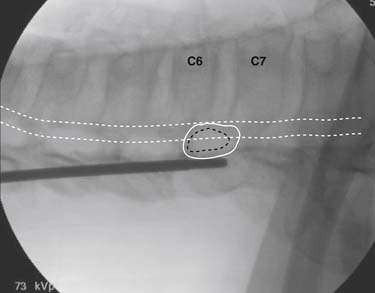
The skin is marked and if desired, a skin wheal of local anesthetic can be injected. A small-gauge needle is then inserted to contact bone, SAP, dorsal to the apparent foramen (Fig. 35-39). One of the authors (ML) prefers a slight bend on the tip of the needle to increase maneuverability and control. However, an opposing opinion (CA) prefers a straight needle because the radius circumscribed by a bent needle tip with rotation can be considered a “cutting weapon” and might damage any neural or vascular structures that are encountered. Because the actual distance between skin and foramen is rarely greater than 1.5 inches, and a slight misdirection of the needle can easily lead to placement into a potentially perilous structure (Fig. 35-40), a technique in which the needle is advanced quickly under active fluoroscopy is thought to be safest. In addition, if pressure is applied with a blunt instrument during needle insertion, soft tissue is distracted, and the actual depth to target is usually less than one-half inch. This pressure is then released and the skin draws back over the needle, securing it in place. This technique can be accomplished in less than 1 second, and some radiation exposure to the dominant hand is inevitable (see Fig. 35-39). Using pulsed, low-dose fluoroscopic modes, the radiation dose is low, and the perceived safety factor afforded by this technique is appealing. This technique is analogous to that used for cervical discography and stellate ganglion blocks.
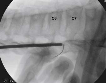
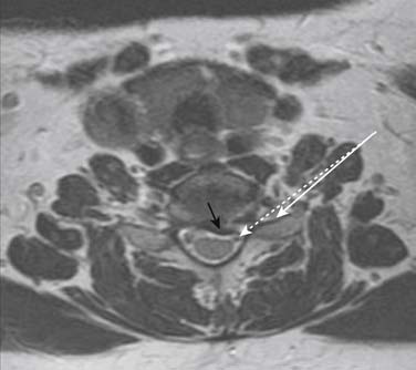
When the SAP is contacted dorsal to the perceived foramen, all further advancement of the needle is immediately stopped until depth can be ascertained (Fig. 35-41, A). If the needle is additionally inserted at this point, entry into the central spinal canal can easily occur (see Fig. 35-40). An AP view (Fig. 35-41, B) verifies medial-lateral position. The needle tip should be seen as lying over the mid-aspect of the articular pillar. The needle can be advanced toward the uncinate because the dural root sleeves in the cervical spine do not extend laterally to the degree observed in the lumbar spine and vascular structures are less prevalent in this area.
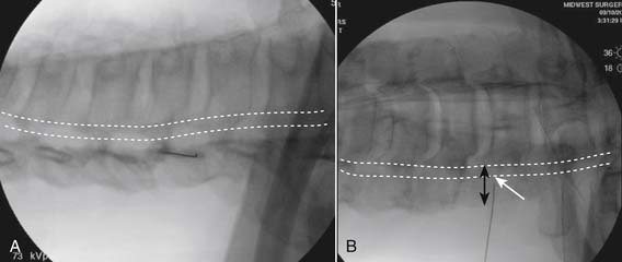
At this juncture, images documenting precontrast needle position are archived. The foraminal view (Fig. 35-41, A) shows the needle in the dorsal foramen contacting the SAP, whereas the AP view (see Fig. 35-41, B) documents that encroachment of the central canal has not occurred. A needle inadvertently placed ventral within the foramen owing to slight error in angle of insertion, might easily puncture the vertebral artery.
Using active fluoroscopy in the AP view, with DSI if available, contrast is injected to ensure a safe pattern. Flow should be seen through the foramen and into the lateral epidural space (Fig. 35-42). If marked foraminal stenosis is present, minimal contrast may be seen entering the spinal canal. A transient mild to moderate, pressure paresthesia is often noted by the patient secondary to neural stimulation. If significant venous uptake is evident, the needle can be repositioned slightly, either medially toward the uncinate process or laterally, while staying in touch with the SAP. One then reinjects contrast until a safe pattern is noted. If vascular flow to the midspinal canal is evident, the medullary artery may have been cannulated, and the procedure must be terminated. If apparent filling of a tubular structure is noted lateral to the uncinate process in AP view, and over the uncinate line in foraminal view, vertebral artery injection—either intramural or intraluminal—must be considered strongly and the procedure terminated. If there is any question in the operator’s mind about the safety of the injection, the procedure should be terminated immediately.
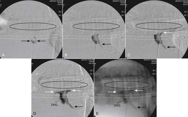
As noted above, some injectionists, including one of the authors (CA), prefer to inject a test dose of local anesthetic prior to the corticosteroid and wait 2 minutes looking for neurologic sequelae correlated with an anesthetized spinal cord. When a safe contrast pattern has been obtained in both AP and foraminal views (see Figs. 35-42, E and 35-43), images are saved for the historical record of the procedure. The nonparticulate corticosteroid can be injected with diluent of choice.
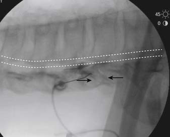
Postprocedure Care
The patient is taken to a recovery area for observation where physiologic monitoring is continued until discharge. Recovery room personnel should be trained to recognize any emergent situations that may present. Complications require diagnosis and treatment in a timely and appropriate manner. Although rarely needed, immediate access to oxygen, airway supplies, and emergency medications must be available. Because sensory and/or motor deficit is often noted when local anesthetics are used, neurologic assessment is of particular importance. If a lumbar injection has been completed, it is prudent to ascertain that the patient has sufficient control of the lower extremities to stand and walk, and assistance on rising should be initially provided. Any motor deficit will rapidly reverse if reasonable doses of local anesthetic were used.
Prior to discharge, if a more selective injection (i.e., transforaminal versus interlaminar) was completed with local anesthetic, the patient is evaluated for degree of pain relief compared with initial, preprocedure level. Assessment by the physician, or other trained personnel, must include those provocative movements which initiate an increase in the index pain. Appraisal of pain intensity change following a procedure with the patient lying comfortably in a bed is of no value. Following an L5-S1 transforaminal injection, the postprocedure neurologic examination would be expected to evidence weakness in extensor hallucis longus, and sensory decrease of the dorsal foot and great toe. These findings validate the procedure because if present, a response to the corticosteroid might be reasonably expected. If sensory deficit in the selected target dermatome was noted, but the patient continued to realize his initial level of pain, either a technical problem occurred or the diagnosis of L5 radicular pain must be reconsidered. This postprocedure evaluation must be included in the specific, detailed, accurate procedure note dictated following any medical intervention (see appendix A and B).
Summary
As with all medical interventions, there is a risk-benefit ratio that must be considered. Transforaminal and interlaminar epidural injections can involve significant morbidity and even mortality. However, with prudence, vigilance, and meticulous technique, these risks are well managed by a fully trained Interventional Pain Management/Nonsurgical Spine Specialist.
A Sample Dictation for Lumbar Interlaminar Epidural
Mrs. Jones was discharged home in her husband’s care and will follow up with her PCP, Dr. Smith in the near future. She will follow up with this physician if any problems occur or in 2 weeks by telephone because she lives 4 hours from this facility. She understands that if two to three epidural corticosteroid injections in any 6-month period provide good relief and allow her to maintain her activities of daily living, this is an appropriate palliative treatment modality.
B Sample Dictation for Cervical Transforaminal
Mr. Jones tolerated the procedure well and was taken to recovery in stable condition. Thirty minutes postprocedure, he evidenced a marked C6 sensory deficit owing to the local anesthetic effect, and noted “95%” relief of his usual, preprocedure pain with provocative movements. Although not diagnostic, this indicates probable coverage of the pain generator. He was discharged home in stable condition in his wife’s care. He will follow up in 2 to 3 weeks for reevaluation and possible additional injections, if appropriate.
1. Evans W. Intrasacral epidural injection in the treatment of sciatica. Lancet. 1930;2:1225.
2. Robecchi A., Capra R. Intrasacral epidural injection in the treatment of sciatica. Minerva Med. 1952;98:1259.
3. Lievre J.A., Bloch-Michel H., Pean G. L’hydrocortisone en injection locale. Rheumatism. 1953;20:310.
4. Gardner W.J., Goebert H.W.Jr., Sehgal A.D. Intraspinal corticosteroids in the treatment of sciatica. Trans Am Neurol Assoc. 1961;86:214-215.
5. Barry P.J., Kendall P.H. Corticosteroid infiltration of the extradural space. Ann Phys Med. 1962;6:267-273.
6. Goebert H.W.Jr., Jallo S.J., Gardner W.J., et al. Painful radiculopathy treated with epidural injections of procaine and hydrocortisone acetate: Results in 113 patients. Anesth Analg. 1961;40:130-134.
7. Krempen J.F., Smith B.S. Nerve-root injection: A method for evaluating the etiology of sciatica. J Bone Joint Surg Am. 1974;56:1435-1444.
8. Tajima T., Furukawa K., Kuramochi E. Selective lumbosacral radiculography and block. Spine. 1980;5:68-77.
9. Stanley D., McLaren M.I., Euinton H.A., et al. A prospective study of nerve root infiltration in the diagnosis of sciatica. A comparison with radiculography, computed tomography, and operative findings. Spine. 1990;15:540-543.
10. Catchlove R.F., Braha R. The use of cervical epidural nerve blocks in the management of chronic head and neck pain. Can Anaesth Soc J. 1984;31:188-191.
11. Rowlingson J.C., Kirschenbaum L.P. Epidural analgesic techniques in the management of cervical pain. Anesth Analg. 1986;65:938-942.
12. Warfield C.A., Biber M.P., Crew D.A., et al. Epidural steroid injection in the treatment for cervical radiculitis. Clin J Pain. 1988;4:201-204.
13. Morvan G., Mempoint D., Bard M., et al. Direct intra-foraminal injection of corticosteroids in the treatment of cervico-brachial pain. In: Baird M., Laredo J., editors. Interventional Radiology in Bone and Joint. New York: Springer Verlag; 1988:25.
14. Bush K., Hillier S. Outcome of cervical radiculopathy treated with periradicular/epidural corticosteroid injections: A prospective study with independent clinical review. Eur Spine J. 1996;5:319-325.
15. Vallee J.N., Feydy A., Carlier R.Y., et al. Chronic cervical radiculopathy: Lateral-approach periradicular corticosteroid injection. Radiology. 2001;218:886-892.
16. Slipman C.W., Lipetz J.S., Jackson H.B., et al. Therapeutic selective nerve root block in the nonsurgical treatment of atraumatic cervical spondylotic radicular pain: A retrospective analysis with independent clinical review. Arch Phys Med Rehabil. 2000;81:741-746.
17. Forrest J.B. Management of chronic dorsal root pain with epidural steroid. Can Anaesth Soc J. 1978;25:218-225.
18. Ramamurthy S. Thoracic epidural block. In: Waldman S.D., editor. Interventional Pain Medicine. 2nd ed. Philadelphia: WB Saunders; 2001:390.
19. Yin W. A posterior parasagittal approach to thoracic paravertebral structures with curved cannulae. Tech Regl Anesth Pain Manag. 2001;5:157.
20. Friedly J., Chan L., Deyo R. Increases in lumbosacral injections in the Medicare population: 1994 to 2001. Spine. 2007;32:1754-1760.
21. Carrino J.A., Morrison W.B., Parker L., et al. Spinal injection procedures: Volume, provider distribution, and reimbursement in the U.S. medicare population from 1993 to 1999. Radiology. 2002;225:723-729.
22. Vroomen P.C., de Krom M.C., Slofstra P.D., Knottnerus J.A. Conservative treatment of sciatica: A systematic review. J Spinal Disord. 2000;13:463-469.
23. Levin J.H. Prospective, double-blind, randomized placebo-controlled trials in interventional spine: What the highest quality literature tells us. Spine J. 2009;9:690-703.
24. Fitzgibbon D.R., Posner K.L., Domino K.B., et al. Chronic pain management: American Society of Anesthesiologists Closed Claims Project. Anesthesiology. 2004;100:98-105.
25. Wiltse L.L., Fonseca A.S., Amster J., et al. Relationship of the dura, Hofmann’s ligaments, Batson’s plexus, and a fibrovascular membrane lying on the posterior surface of the vertebral bodies and attaching to the deep layer of the posterior longitudinal ligament. An anatomical, radiologic, and clinical study. Spine. 1993;18:1030-1043.
26. Tarlov I.M. Spinal perineurial and meningeal cysts. J Neurol Neurosurg Psychiatry. 1970;33:833-843.
27. Langdown A.J., Grundy J.R., Birch N.C. The clinical relevance of Tarlov cysts. J Spinal Disord Tech. 2005;18:29-33.
28. Beaujeux R., Wolfram-Gabel R., Kehrli P., et al. Posterior lumbar epidural fat as a functional structure? Histologic specificities. Spine. 1997;22:1264-1268.
29. Scapinelli R. Anatomical and radiologic studies on the lumbosacral meningo-vertebral ligaments of humans. J Spinal Disord. 1990;3:6-15.
30. Blomberg R. The dorsomedian connective tissue band in the lumbar epidural space of humans: An anatomical study using epiduroscopy in autopsy cases. Anesth Analg. 1986;65:747-752.
31. Crock H.V., Yoshizawa H., Kame S.K. Observations on the venous drainage of the human vertebral body. J Bone Joint Surg Br. 1973;55:528-533.
32. Gershater R., St Louis E.L. Lumbar epidural venography. Review of 1,200 cases. Radiology. 1979;131:409-421.
33. Dommisse G.T. The Arteries and Veins of the Human Spinal Cord from Birth. New York: Churchill Livingstone; 1975. 51
34. Turnbull I.M., Brieg A., Hassler O. Blood supply of cervical spinal cord in man. A microangiographic cadaver study. J Neurosurg. 1966;24:951-965.
35. Launay M., Chiras J., Bories J. Angiography of the spinal cord: Venous phase. Normal features. Pathological application. J Neuroradiol. 1979;6:287-315.
36. Dommisse G.F. The arteries, arterioles, and capillaries of the spinal cord. Surgical guidelines in the prevention of postoperative paraplegia. Ann R Col Surg Engl. 1980;62:369-376.
37. Huntoon M.A. Anatomy of the cervical intervertebral foramina: Vulnerable arteries and ischemic neurologic injuries after transforaminal epidural injections. Pain. 2005;117:104-111.
38. Doppman J., Di Chiro G. The arteria radicularis magna: Radiographic anatomy in the adult. Br J Radiol. 1968;41:40-45.
39. Lo D., Vallee J.N., Spelle L., et al. Unusual origin of the artery of Adamkiewicz from the fourth lumbar artery. Neuroradiology. 2002;44:153-157.
40. Parke W.W., Watanabe R. The intrinsic vasculature of the lumbosacral spinal nerve roots. Spine. 1985;10:508-515.
41. Lazorthes G., Poulhes J., Bastide G., et al. [Arterial vascularization of the spine; anatomic research and applications in pathology of the spinal cord and aorta]. Neurochirurgie. 1958;4:3-19.
42. Merskey H., Bogduk N., editors. Classification of Chronic Pain. Descriptions of Chronic Pain Syndromes and Definition of Pain Terms, 2nd ed., Seattle: IASP Press, 1994.
43. Smyth M.J., Wright V. Sciatica and the intervertebral disc. An experimental study. J Bone Joint Surg Am. 1958;40A:1401-1418.
44. Govind J. Lumbar radicular pain. Aust Fam Physician. 2004;33:409-412.
45. Okada E., Matsumoto M., Ichihara D., et al. Aging of the cervical spine in healthy volunteers: A 10-year longitudinal magnetic resonance imaging study. Spine. 2009;34:706-712.
46. Ernst C.W., Stadnik T.W., Peeters E., et al. Prevalence of annular tears and disc herniations on MR images of the cervical spine in symptom free volunteers. Eur J Radiol. 2005;55:409-414.
47. Boos N., Rieder R., Schade V., et al. 1995 Volvo Award in clinical sciences. The diagnostic accuracy of magnetic resonance imaging, work perception, and psychosocial factors in identifying symptomatic disc herniations. Spine. 1995;20:2613-2625.
48. Tafazal S., Ng L., Chaudhary N., et al. Corticosteroids in peri-radicular infiltration for radicular pain: A randomised double blind controlled trial. One year results and subgroup analysis. Eur Spine J. 2009;18:1220-1225.
49. Schofferman J., Anderson D., Hines R., et al. Childhood psychological trauma and chronic refractory low-back pain. Clin J Pain. 1993;9:260-265.
50. Nickel R., Egle U.T., Hardt J. Are childhood adversities relevant in patients with chronic low back pain? Eur J Pain. 2002;6:221-228.
51. Linton S.J. A prospective study of the effects of sexual or physical abuse on back pain. Pain. 2002;96:347-351.
52. Wang C.L., Cohan R.H., Ellis J.H., et al. Frequency, outcome, and appropriateness of treatment of nonionic iodinated contrast media reactions. AJR Am J Roentgenol. 2008;191:409-415.
53. Shetty S.K., Nelson E.N., Lawrimore T.M., Palmer W.E., et al. Use of gadolinium chelate to confirm epidural needle placement in patients with an iodinated contrast reaction. Skeletal Radiol. 2007;36:301-307.
54. Solomon R., Dumouchel W. Contrast media and nephropathy: Findings from systematic analysis and Food and Drug Administration reports of adverse effects. Invest Radiol. 2006;41:651-660.
55. Parra D., Legreid A.M., Beckey N.P., et al. Metformin monitoring and change in serum creatinine levels in patients undergoing radiologic procedures involving administration of intravenous contrast media. Pharmacotherapy. 2004;24:987-993.
56. Hodgson P.S., Neal J.M., Pollock J.E., Liu S.S. The neurotoxicity of drugs given intrathecally (spinal). Anesth Analg. 1999;88:797-809.
57. Braid D.P., Scott D.B. The systemic absorption of local analgesic drugs. Br J Anaesth. 1965;37:394-404.
58. Covino B. Clinical pharmacology of local anesthetic agents. In: Cousins M., Bridenbaugh P., editors. Neural Blockade in Clinical Anesthesia and Management of Pain. Philadelphia: JB Lippincott; 1988:111.
59. Jorfeldt L., Lofstrom B., Pernow B., et al. The effect of local anaesthetics on the central circulation and respiration in man and dog. Acta Anaesthesiol Scand. 1968;12:153-169.
60. Mather L.E., Tucker G.T., Murphy T.M., et al. Cardiovascular and subjective central nervous system effects of long-acting local anaesthetics in man. Anaesth Intensive Care. 1979;7:215-221.
61. Benyamin R.M., Vallejo R., Kramer J., Rafeyan R. Corticosteroid induced psychosis in the pain management setting. Pain Physician. 2008;11:917-920.
62. Tuel S.M., Meythaler J.M., Cross L.L. Cushing’s syndrome from epidural methylprednisolone. Pain. 1990;40:81-84.
63. Benzon H.T. Epidural steroid injections for low back pain and lumbosacral radiculopathy. Pain. 1986;24:277-295.
64. Gaul C., Neundorfer B., Winterholler M. Iatrogenic (para-) spinal abscesses and meningitis following injection therapy for low back pain. Pain. 2005;116:407-410.
65. Kaspar J., Kaspar S., Orme C., et al. Intra-articular steroid hip injection for osteoarthritis: A survey of orthopedic surgeons in Ontario. Can J Surg. 2005;48:461-469.
66. Ward A., Watson J., Wood P., et al. Glucocorticoid epidural for sciatica: Metabolic and endocrine sequelae. Rheumatology (Oxford). 2002;41:68-71.
67. Gonzalez P., Laker S.R., Sullivan W., et al. The effects of epidural betamethasone on blood glucose in patients with diabetes mellitus. PM R. 2009;1:340-345.
68. Younes M., Neffati F., Touzi M., et al. Systemic effects of epidural and intra-articular glucocorticoid injections in diabetic and non-diabetic patients. Joint Bone Spine. 2007;74:472-476.
69. Manchikanti L., Pampati V., Beyer C., et al. The effect of neuraxial steroids on weight and bone mass density: A prospective evaluation. Pain Physician. 2000;3:357-366.
70. Bernat J.L. Intraspinal steroid therapy. Neurology. 1981;31:168-171.
71. Windsor R.E., Storm S., Sugar R. Prevention and management of complications resulting from common spinal injections. Pain Physician. 2003;6:473-483.
72. Kabbara A., Rosenberg S.K., Untal C. Methicillin-resistant Staphylococcus aureus epidural abscess after transforaminal epidural steroid injection. Pain Physician. 2004;7:269-272.
73. Hooten W.M., Kinney M.O., Huntoon M.A. Epidural abscess and meningitis after epidural corticosteroid injection. Mayo Clin Proc. 2004;79:682-686.
74. Furman M.B., O’Brien E.M., Zgleszewski T.M. Incidence of intravascular penetration in transforaminal lumbosacral epidural steroid injections. Spine. 2000;25:2628-2632.
75. Furman M.B., Giovanniello M.T., O’Brien E.M. Incidence of intravascular penetration in transforaminal cervical epidural steroid injections. Spine. 2003;28:21-25.
76. Kim do W., Han K.R., Kim C., Chae YJ., et al. Intravascular flow patterns in transforaminal epidural injections: A comparative study of the cervical and lumbar vertebral segments. Anesth Analg. 2009;109:233-239.
77. Botwin K.P., Castellanos R., Rao S., et al. Complications of fluoroscopically guided interlaminar cervical epidural injections. Arch Phys Med Rehabil. 2003;84:627-633.
78. Cicala R.S., Thoni K., Angel J.J. Long-term results of cervical epidural steroid injections. Clin J Pain. 1989;5:143-145.
79. Botwin K.P., Baskin M., Rao S. Adverse effects of fluoroscopically guided interlaminar thoracic epidural steroid injections. Am J Phys Med Rehabil. 2006;85:14-23.
80. Horlocker T.T., Wedel D.J., Benzon H., et al. Regional anesthesia in the anticoagulated patient: Defining the risks (the second ASRA Consensus Conference on Neuraxial Anesthesia and Anticoagulation). Reg Anesth Pain Med. 2003;28:172-197.
81. Stoll A., Sanchez M. Epidural hematoma after epidural block: Implications for its use in pain management. Surg Neurol. 2002;57:235-240.
82. Williams K.N., Jackowski A., Evans P.J. Epidural haematoma requiring surgical decompression following repeated cervical epidural steroid injections for chronic pain. Pain. 1990;42:197-199.
83. Layton K.F., Kallmes D.F., Horlocker T.T. Recommendations for anticoagulated patients undergoing image-guided spinal procedures. AJNR Am J Neuroradiol. 2006;27:468-470.
84. Schulman J. Treatment of neck pain with cervical epidural steroid injection. Reg Anesth. 1986;11:92-94.
85. Derby R., Lee S.H., Kim B.J., et al. Complications following cervical epidural steroid injections by expert interventionalists in 2003. Pain Physician. 2004;7:445-449.
86. Hodges S.D., Castleberg R.L., Miller T., et al. Cervical epidural steroid injection with intrinsic spinal cord damage. Two case reports. Spine. 1998;23:2137-2142.
87. Tripathi M., Nath S.S., Gupta R.K. Paraplegia after intracord injection during attempted epidural steroid injection in an awake-patient. Anesth Analg. 2005;101:1209-1211.
88. Pounder D., Elliott S. An awake patient may not detect spinal cord puncture. Anaesthesia. 2000;55:194.
89. Mayall M.F., Calder I. Spinal cord injury following an attempted thoracic epidural. Anaesthesia. 1999;54:990-994.
90. Baker R., Dreyfuss P., Mercer S., Bogduk N., et al. Cervical transforaminal injection of corticosteroids into a radicular artery: A possible mechanism for spinal cord injury. Pain. 2003;103:211-215.
91. Rathmell J.P., Aprill C., Bogduk N. Cervical transforaminal injection of steroids. Anesthesiology. 2004;100:1595-1600.
92. Bogduk N., Dreyfuss P., Baker R., et al. Complications of spinal diagnostic and treatment procedures. Pain Med. 2008;9:S11-S34.
93. Brouwers P.J., Kottink E.J., Simon M.A., Prevo R.L., et al. A cervical anterior spinal artery syndrome after diagnostic blockade of the right C6-nerve root. Pain. 2001;91:397-399.
94. Houten J.K., Errico T.J. Paraplegia after lumbosacral nerve root block: Report of three cases. Spine J. 2002;2:70-75.
95. Glaser S.E., Falco F. Paraplegia following a thoracolumbar transforaminal epidural steroid injection. Pain Physician. 2005;8:309-314.
96. Yin W., Bogduk N. Retrograde filling of a thoracic spinal artery during transforaminal injection. Pain Med. 2009;10:689-692.
97. Scanlon G.C., Moeller-Bertram T., Romanowsky S.M., Wallace M.S. Cervical transforaminal epidural steroid injections: More dangerous than we think? Spine. 2007;32:1249-1256.
98. Kennedy D.J., Dreyfuss P., Aprill C.N., Bogduk .N., et al. Paraplegia following image-guided transforaminal lumbar spine epidural steroid injection: Two case reports. Pain Med. 2009;10:1389-1394.
99. Karasek M., Bogduk N. Temporary neurologic deficit after cervical transforaminal injection of local anesthetic. Pain Med. 2004;5:202-205.
100. Derby R., Lee S.H., Date E.S., et al. Size and aggregation of corticosteroids used for epidural injections. Pain Med. 2008;9:227-234.
101. Tiso R.L., Cutler T., Catania J.A., Whalen K. Adverse central nervous system sequelae after selective transforaminal block: The role of corticosteroids. Spine J. 2004;4:468-474.
102. Dreyfuss P., Baker R., Bogduk N. Comparative effectiveness of cervical transforaminal injections with particulate and nonparticulate corticosteroid preparations for cervical radicular pain. Pain Med. 2006;7:237-242.
103. Okubadejo G.O., Talcott M.R., Schmidt R.E., et al. Perils of intravascular methylprednisolone injection into the vertebral artery. An animal study. J Bone Joint Surg Am. 2008;90:1932-1938.
104. Dawley J.D., Moeller-Bertram T., Wallace M.S., Patel P.M. Intra-arterial injection in the rat brain: Evaluation of steroids used for transforaminal epidurals. Spine. 2009;34:1638-1643.
105. Renfrew D.L., Moore T.E., Kathol M.H., et al. Correct placement of epidural steroid injections: Fluoroscopic guidance and contrast administration. AJNR Am J Neuroradiol. 1991;12:1003-1007.
106. White A.H., Derby R., Wynne G. Epidural injections for the treatment of low back pain. Spine. 1980;5:78-86.
107. Stitz M.Y., Sommer H. Accuracy of blind versus fluoroscopically guided caudal epidural injections. Spine. 1999;24:1371-1376.
108. Judge Janice Clark. State of Louisiana 19th Judicial District, #536,009, Spinal Diagnostics Center of Baton Rouge versus Louisiana State Board of Nursing, 10 January 2007.
109. American Medical Association House of Delegates. Resolution #903. Interventional Pain Management: Advancing Advocacy to Protect Patients from Treatment by Unqualified Providers: 24 September 2007.
110. International Spine Intervention Society. Position Statement. Prerequisite Training for the Performance of Spine Interventions. 25 September 2006.
111. American Society of Anesthesiologists. Committee on Pain Medicine. Statement on Nurse Anesthesia Training in Pain Medicine. 25 March 2004.
112. Fenton D.S., Czervionke L.F. Selective Nerve Root Block. In: Fenton D.S., Czervionke L.F., editors. Image-Guided Spine Intervention. Philadelphia: Saunders; 2003:73-97.
113. Bogduk N., editor. Practice Guidelines: Spinal Diagnostic & Treatment Procedures. San Francisco: International Spine Intervention Society, 2004.
114. Pauza K.J. PASSOR Educational Guidelines for the performance of spinal injection procedures. PASSOR Board of Governors and AAPMR Board of Governors. 2001.
115. Bogduk N. Sharp vs. blunt needles—International Spine Intervention Society White Paper. Interventional Spine. 2006;5:7-13.
116. Pauza K. A comparison of blunt vs. sharp needles with respect to intravascular injection. Salt Lake City: International Spine Intervention Society, Annual Meeting; 2006.
117. Derby R., Date E.S., Lee C.H., et al. Size and aggregation of corticosteroids used for epidural injections. Interventl Spine. 2006;5:30-37.
118. Bogduk N., editor. Practice Guidelines: Spinal Diagnostic & Treatment Procedures. San Francisco: International Spine Intervention Society, 2004.
119. Derby R. Point of view: cervical epidural steroid injection with intrinsic spinal cord damage: two case reports. Spine. 1998;23:2141-2142.
120. Aldrete J.A., Mushin A.U., Zapata J.C., Ghaly R. Skin to cervical epidural space distances as read from magnetic resonance imaging films: Consideration of “hump pad”. J Clin Anesth. 1998;10:309-313.
121. Alleyne Jr C.H., Cawley C.M., Shengelaia G.G., Barrow D.L. Microsurgical anatomy of artery of Adamkiewicz and its segmental artery. J Neurosurg. 1998;89:791-795.
122. Bogduk N., editor. Lumbar transforaminal injection of corticosteroids. In Practice Guidelines: Spinal Diagnostic & Treatment Procedures. San Francisco: International Spine Intervention Society. 2004:163-187.
123. Karasek M., Bogduk N. Temporary neurological deficit after cervical transforaminal injection of local anesthetic. Pain Med. 2004;5:202-205.
[/level-membership-for-physical-medicine-and-rehabilitation-category][not-level-membership-for-physical-medicine-and-rehabilitation-category]
35 Epidural Steroid Injections
Cervical, Thoracic, and Lumbar: Transforaminal, Interlaminar, and Caudal
History
There is a report in English literature that refers to the caudal injection approach for pain management in 1930.1 The first recorded use of corticosteroids injected into the epidural space for the treatment of “sciatica” was in 1952.2 The route of administration was one of the dorsal foramina of the sacrum, an early, blind, transforaminal technique. This technique was employed in Europe in the 1950s and 60s.3
Interlaminar approaches to the lumbar epidural space were reported in the 1960s.4–6 Caudal and interlaminar techniques became standard practice in the United States, Britain, and most of continental Europe for the next quarter century. Interest in the transforaminal approach reemerged in the last quarter of the 20th century, in an attempt to deliver more target-specific injections.7–9 The cervical literature is sparse by comparison to that of the lumbar spine. The interlaminar approach for epidural injections was generally used in the 1980s.10–12 Cervical transforaminal injection was first reported in 1988.13 A descriptive outcome study by Bush and Hillier employing this approach followed in 1996.14 The transforaminal approach was adopted to deliver therapeutic agents to more specific targets influenced by observations that lumbar transforaminal injections appeared to be effective in treating lumbar radicular pain.15,16
There are few reports of the origin of thoracic epidural steroid injections (ESIs) for treatment of spinal pain.17,18 A specific technique for thoracic transforaminal epidural injection was described in 2001.19
A recent systematic review revealed an increase in the number of lumbosacral spine injection procedures performed in the last decade of the twentieth century. There was an increase of more than 270% noted between 1994 and 2001.20 Forty percent of these procedures were associated with the diagnosis codes for “sciatica,” “radiculopathy” or “herniated disc.” “Axial low back pain” diagnoses accounted for 36% and “spinal stenosis” 23%. A study of the Medicare population between 1993 and 1999 revealed that the annual number of cervical, thoracic, and lumbar epidural steroid injections peaked at more than 680,000 in 1998.21 These studies focused on the Medicare population, but it is likely that similar increases would be found for the general adult pain population.
A review of conservative care for sciatica published in 2000 surveyed 19 randomized controlled trials and pooled odds ratios calculated for several treatment types. The data indicated, “Epidural steroids may be beneficial for subgroups of nerve root compression.”22
In 2009, Lavin published results of an extensive MEDLINE/PubMed search and searches of large review articles on the major interventional spine topics. This review was performed to find all prospective, double-blind, randomized, placebo-controlled trials in the English language interventional spine literature. He concluded “Fluoroscopically guided lumbosacral transforaminal epidural corticosteroid injections are effective in the treatment of acute/subacute lumbosacral radicular pain, and in preventing future surgeries. No firm conclusions were drawn about cervical epidural (CESI) injections or lumbosacral epidural (LESI) injections for the treatment of chronic radicular pain.23 A study of the American Society of Anesthesiologists (ASA) Closed Claims Project database revealed that epidural steroid injections account for more complications than any other interventional pain procedure.24
Relevant Anatomy
The spinal epidural space is a continuous potential space in the vertebral canal extending from the foramen magnum to the sacral hiatus, lying between the dural sac and the osseoligamentous wall of the vertebral canal. The epidural space is bounded posteriorly by the lamina and ligamentum flavum. The anterior boundary is formed by the posterior disc margin, the posterior longitudinal ligament and the peridural membrane. This membrane attached to the upper and lower ring apophysis of each vertebra, blends with the disc annulus. It spans the waist of the vertebral body.25 Together these tissues form the floor of the vertebral canal. The lateral boundary of the epidural space is fenestrated by paired root canals or foramina at each segment. The vertebral pedicles lie between the root canals.
The dural sac nearly fills the vertebral canal and extends from the foramen magnum terminating in the sacral canal at the level of the S1 to S2 segments. There is some variability and the thecal sac may terminate as high as the lumbosacral interspace or may extend to S3. At each vertebral segment paired dural root sleeves extend toward the root canals. The cervical and thoracic dural root sleeves are short and nearly horizontal in orientation, traversing the center of their respective root canals. The lumbar root sleeves are longer, increasing slightly in length and downward angle from L1 to the sacrum. Lumbar root sleeves turn laterally into grooves in the vertebral bodies and pedicles and are in intimate proximity to the medial/inferior border of the pedicles. This is the entrance zone of the root canal, or lateral recess of the vertebral canal. The dural root sleeve contains the dorsal and ventral rootlets of the segmental nerve. The dorsal ganglia lie generally in the midzone of the root canals, between the pedicles of adjacent vertebra. The dura and arachnoid membranes form a “water-tight” seal at the proximal end of the ganglia. Cerebrospinal fluid (CSF) fills the root sleeve but does not extend beyond the ganglia. Occasionally ectasia of a dural root sleeve will occur, resulting in extension of the subarachnoid space beyond usual boundaries. Referred to as cystic root sleeve dilatation or Tarlov cysts, they usually communicate freely with the subarachnoid space.26 They may occur at any level of the spine but are most frequent in the sacral region. Usually asymptomatic, they are rarely associated with symptoms.27
There are accumulations of fat in the posterior vertebral canal, deep to the ligamentum flavum and posterior to the dural sac in the thoracic and lumbar spine.28 This posterior fat pad may be small or absent at the L5-S1 level when the dural sac is full size and is applied close to the lamina and ligamentum flavum, as it frequently is. Additional accumulations of fat are found laterally at the level of the discs within the root canals. There is little fat in the cervical epidural space. Midline sagittal spin echo (SE) T1 images of the spine demonstrate the lumbar and thoracic fat pads quite well. Fat is rarely visualized in the vertebral canal above the C7-T1 level. Ample fat fills the vertebral canal below the termination of the dural sac in the sacral vertebral canal.
A thin anterior membrane extends from the posterior longitudinal ligament to the anterior surface of the dural sac. This ventral meningovertebral ligament forms a nearly continuous septum, that functionally divides the ventral epidural space into left and right compartments in the lumbar region.29 A midline dorsal connective tissue band fixes the dural sac to the flaval ligaments. The appearance of the band varies from strands of connective tissue to a complete membrane.30
A plexus of valveless veins occupies the anterior epidural space.31 Paired anterior internal epidural veins run the length of the vertebral canal. There are numerous interconnecting veins crossing the floor of the canal, the anterior internal vertebral venous plexus (AIVV).32 A smaller posterior internal venous plexus lines the roof of the epidural space in the lumbar and thoracic regions. Extending laterally around the vertebra, the peridural membrane encloses veins that course around the body of the vertebra.25 These veins communicate freely with the basivertebral veins, at the center of the posterior wall of each vertebral body and the anterior internal vertebral venous plexus. Several radicular veins traverse each root canal. They lie predominantly in the ventral root canal and connect the epidural venous plexus with the ascending lumbar veins and the vena cava.
Segmental arteries traverse the root canals at all spinal levels.33 They course in the anterior superior root canals along the anterior superior aspect of the segmental dural root sleeve. Some arterial branches perfuse the dorsal ganglia and segmental neural elements and, as such, are radicular arteries. Other branches penetrate the dura running along the segmental rootlets and may anastomose with the anterior spinal artery. They are, therefore, medullary arteries. Varying numbers of medullary arteries of differing sizes are found in the cervical, thoracic, and lumbar region, and contribute to the blood supply of the spinal cord.
The radicular and medullary arteries of the cervical spine arise primarily from the vertebral artery.34,35 Some arise from the ascending cervical and posterior cervical arteries. Medullary arteries penetrate the dura and divide into anterior and posterior branches, eventually reaching the anterior and paired posterior spinal arteries. Cervical medullary arteries are variable in size and distribution. There are usually two or three arteries of moderate size in the adult. They may be present at any segment and on either side.36,37
The upper and midthoracic cord is supplied by medullary arteries arising from branches of the costocervical trunk and spinal branches of the aorta. There is usually a single large medullary artery arising from the aorta and supplying blood to the lower half of the thoracic cord and conus. This large medullary artery, the artery of Adamkiewicz, has a variable origin but usually originates on the left side (80% of patients), between T7 to L4, most often between T9 and T11.38 In a study of 4000 spinal cord angiograms, there were three instances in which the major medullary artery of the distal thoracic cord originated at the fourth lumbar artery.39
Paired lumbar arteries originate from the aorta at each lumbar segment. These give rise to spinal branches that include radicular and medullary branches.40 Most lumbar spinal branches are small. Some may be 1.0 to 2.0 mm in diameter. There is potential for a medullary artery of substantial size to be present in any root canal.41
Spondylogenic Pain
Spondylogenic pain arises from a component of the spine or its supporting structures, and is synonymous with other terms such as nonspecific or idiopathic spinal pain. The International Association for Study of Pain (IASP) published a taxonomy, defining clinical terms used to describe pain, in an effort to standardize the use of terms.42
Somatic pain results from noxious stimulation of a musculoskeletal component of the body and arises as a result of stimulation of nociceptive nerve endings in bone, ligament, joint, muscle or tendon. Visceral pain occurs with noxious stimulation of a body organ or its capsule. Both somatic and visceral derangements cause pain in the location of the source structure, but it is often vague and ill defined.
Radicular pain occurs when there is irritation or injury of a spinal nerve or its roots. In the lumbar spine, simple compression of a normal nerve or nerve root does not provoke pain.43 Alone, pressure on a spinal nerve or its roots may produce a conduction block of axons. Sensory axon conduction block results in loss of sensation or “numbness.” Motor axon block results in weakness. Compression alone can result in radiculopathy, without radicular pain. Pressure on a previously injured or damaged nerve or root provokes pain. Local ischemia or inflammation can induce ectopic impulses in a dorsal root canal ganglion resulting in radicular pain. Lumbar radicular pain is discretely localized, “bandlike” in distribution, and shooting, lancinating, or shocking in quality44 and can have a cutaneous component.
Preprocedure Evaluation
Spine imaging plays a definite role in the evaluation of spine pain complaints both in demonstrating relevant pathology and aiding in planning a safe and efficient approach for procedures. Modern imaging modalities provide excellent depictions of spine anatomy. However, many lesions, evident in the maturing spine, are clinically insignificant.45 Imaging studies often demonstrate pathology that is irrelevant. Computed tomography (CT) or magnetic resonance imaging (MRI) may demonstrate a left C3-4 disc protrusion in a patient complaining of right arm pain and altered sensation radiating to the right forearm, thumb, and index finger. It cannot be overstated that there is a significant incidence of pathology in asymptomatic subjects.46 A focal disc protrusion on the right at L3-4 may be clearly defined by MRI, in a patient complaining of left buttock pain extending to the left calf.47 Scans should be reviewed overall, but with particular attention to areas that might be related to the patient’s underlying complaints, as gleaned from the interview and examination. One should carefully study the left L4-5 and L5-S1 root canals in a patient with pain extending from the left buttock to the left anterolateral leg and dorsum of the foot. Recently 150 patients with unilateral leg pain, and MRI confirming neural compression by prolapsed disc or foraminal stenosis had lumbar transforaminal epidural injections (LTFE) at appropriate sites. These were effective in relieving their pain initially, and only18% of these patients required surgery at a minimum 1-year follow up.48 Not all abnormalities need be targeted but rather those most likely to be associated with the expressed symptoms and physical findings.
Absolute contraindications include active psychosis and homicidal or suicidal ideation. Studies have shown a relationship between physical and sexual abuse and various types of pain. Correlation of failed low back surgery with childhood trauma has revealed definite risk factors. These include physical, psychological, and/or sexual abuse, emotional neglect, abandonment, and chemical dependence and/or loss of a primary caregiver.49–51 Relative contraindications include personality disorders, bi-polar disorder, severe depression, lack of social support, and drug dependence/abuse.
A Few Medical Issues
Contrast Material
Allergic reactions to modern contrast materials are extremely rare. Some may be related to preservatives such as methylparaben. Wang reviewed 84,928 intravenous contrast injections noting “allergic” reactions in 545 (0.6%).52 Seventy seven percent of the reactions were “mild,” primarily urticaria, successfully treated with diphenhydramine. Twenty one percent had moderate reactions with respiratory symptoms, facial edema, or both. Corticosteroids intravenously or by inhaler were effective in controlling these reactions. Two percent, eight women and three men, had severe reactions (0.0012%). Three were unresponsive; frank cardiorespiratory arrest occurred in one. There were no deaths and no long-term sequelae in 10 of the 11 patients with severe reactions.
Contrast material is employed to document where the injectate is spreading and to determine where it is not spreading. Modern nonionic contrast agents are safe for all epidural injections. Unintentional vascular or even subarachnoid spread will cause no problem. In those very rare instances of documented history of severe allergic reaction to nonionic contrast material, gadolinium may be employed as a substitute radiography contrast agent.53
Diabetics taking metformin are at risk for contrast material nephropathy (CMN) if exposed to nonionic contrast material, during radiographic procedures. Solomon found no change in renal function in those subjects who had normal renal function prior to testing.54 However, some patients with normal renal function exhibited increases of serum creatinine with high-contrast loads.55 This should not be a problem with epidural injections because the contrast doses employed are limited and much lower than the volumes delivered in the radiologic procedures. Doses in excess of 100 mL are not unusual for enhanced CT or angiograms. However, diabetic patients with renal impairment should discontinue metformin, with approval of their primary physician.
Local Anesthetics
The local anesthetics employed in the epidural injections are lidocaine and bupivacaine. These amides are primarily metabolized in the liver and excreted in the urine. Their allergic potential is extremely low. Ester-based local anesthetics (procaine) have a higher incidence of allergic reaction. A large survey attests to the overall safety of the amides as spinal anesthetics.56 For epidural injections, lidocaine may be employed in concentrations of 0.5% to 4.0% and bupivacaine at 0.25% to 0.75%. The percentage concentration of the anesthetic is reduced with increasing volume delivered. Although central nervous system and cardiovascular system toxicity can occur following the epidural, intravenous, or subarachnoid injection of local anesthetics, the toxic doses are far greater than the volumes employed in epidural injections—40 mL of 1.0% lidocaine (400 mg) delivered to the epidural space of test subjects resulted in average peak plasma concentrations safely below neurotoxic levels.57 One author recommended the maximum epidural dose of lidocaine to be 500 mg and 225 mg for bupivacaine.58
Acute cardiac complications, decreased cardiac output being one, can occur from intravascular injection of lidocaine or bupivacaine. Study has shown that normal cardiac function is maintained in subjects with lidocaine plasma levels of 4 to 8 mcg/mL. Plasma levels this high require doses of >400 mg of lidocaine.59 In human volunteers slow intravenous (IV) injection of bupivacaine to produce plasma concentrations equivalent to those achieved during epidural injections did not cause significant cardiovascular change.60 Between 3.0 and 7.0 mL of low concentrations of anesthetics for interlaminar injections and 0.75 to 2.0 mL of higher concentrations for transforaminal injections are not toxic in the epidural space. These doses are not toxic if technical misadventure results in delivery to the vascular system or subarachnoid space. Because of the longer half-life of bupivacaine, this anesthetic should be avoided in interlaminar epidural injections, particularly in the cervical spine. Inadvertent delivery into the subarachnoid or subdural space results in prolonged effects, specifically affecting respiratory function with misplaced cervical injection. Decreased concentration of anesthetics must be considered for interlaminar epidural injections in the cervical and thoracic regions in patients with respiratory or cardiovascular health problems because decreased cardiac output and heart rate can occur with sympathetic blockade, which occurs to some degree with all interlaminar epidural injections.
Corticosteroids
In the central nervous system, nerve tissues exhibit increased excitability, EEG abnormalities are seen, subjects experience euphoria and behavioral changes. Rarely, these effects can be severe. A case report describes 67-year-old male who developed psychotic episodes within a week of a cervical ESI, along with other steroid injections in one treatment session. The symptoms spontaneously resolved in approximately 7 to 10 days.61 This case serves to remind us that we must always be cognizant of the doses we deliver, and remember patients may be receiving “steroid shots” from other physicians for unrelated problems.
Endocrine system alterations include decreased adrenocorticotropic hormone (ACTH), thyroid-stimulating hormone (TSH), and follicle-stimulating hormore (FSH), and testosterone. The changes are largely dose related. Bizarre responses do occur rarely. A 24-year-old man underwent a second cervical ESI of 60 mg of methylprednisolone for ongoing severe arm pain. A cushingoid appearance developed 1 month later. Serum cortisol was undetectable, there was no adrenal response to synthetic ACTH, and urinary-free cortisol was below normal at 12 weeks. Cortisol normalized in 4 months, however, the patient’s cushingoid appearance persisted for 12 months.62
An epidural steroid injection of 160 mg of methylprednisolone will suppress adrenal function for weeks.63 Does injection of corticosteroids increase the risk of infection? Infections do occur in patients following ESIs.64 Postoperative infections are increased in hip replacement patients who received preoperative steroid injections.65 No studies have been done on outcomes of spine surgery after ESI, but suppression of the immune system suggests there is inherent risk, especially in the first 4 weeks post injection.
Epidural administration of glucocorticoids results in potent suppression of insulin action. This should be taken into account when patients with diabetes receive ESIs.66 Lumbosacral transforaminal and caudal epidural betamethasone injections are associated with statistically significant elevations in blood glucose levels in diabetic subjects. This effect peaks on the day of the injection and lasts approximately 2 days.67 The administration of three epidural injections (250 mg prednisone equivalent) was followed by suppression of the corticotropic axis that persisted beyond 21 days. Plasma cortisol and ACTH and urinary free cortisol were markedly reduced at the day 1 and day 7 posttreatment visits, compared to baseline. At 21 days, these variables were still diminished.68 We must be vigilant in follow-up of our diabetic patients.
The musculoskeletal system suffers from some bone mineral density loss, muscle weakness and wasting, and predisposition toward avascular necrosis with long-term oral steroid use. Although systemic corticosteroids may be associated with loss of bone mineral density, a prospective study of 204 patients followed for 1 year after standard doses of epidural steroids revealed no change in bone mineral density.69
The currently used steroids contain preservatives. Bernat thought that seizures following intrathecal cortisone acetate were due to the preservative, 0.9% benzyl alcohol. Benzyl alcohol is common in depot steroids and is neurotoxic.70 Hodgson reported that there was no concrete evidence of neurotoxicity of intrathecal steroids, but did not recommend purposeful delivery of these agents into the subarachnoid space.56
Major Complications
Infection
Infection following epidural injection is a serious issue. It has been described as a rare complication.71 However, the possibility of procedure-related infection must be a concern for the injectionist. Analysis of the American Society of Anesthesiologists (ASA) Closed Claims database from 1970 to 1999 revealed that infection was the third most common complication of chronic pain procedures, accounting for 13% of all complications.24 Any penetration of the skin surface with a needle then placed in deep spaces in and about the spine has the potential of introducing organisms with subsequent infection.72 Standard aseptic preparation and draping of the local injection site and good aseptic technique will minimize this complication. Diabetic and immunocompromised patients are a subgroup that should be recognized prior to procedures. Antibiotic prophylaxis should be considered for immunocompromised patients undergoing ESI.73 Antibiotics should not be mixed with the contrast during any epidural injection. Accidental delivery of antibiotics into the subarachnoid space must be avoided.
Bleeding/Hematoma
Many veins lie in the needle path or near endpoint targets of transforaminal epidural injections (TFESI). Furman and colleagues reported the incidence of fluoroscopically confirmed “vascular uptake” occurring during lumbar74 and cervical75 transforaminal injections. Observing blood at the needle hub reliably predicts intravascular injection, (97% specific). But this finding has low sensitivity, (45% overall). The absence of blood in the needle hub despite aspiration is not reliable. The incidence of vascular uptake with lumbar procedures is about 11%. There is a higher incidence in the cervical spine where confirmed intravascular injection was observed in nearly 20% of patients. Kim and coworkers have recently reported a much higher rate of vascular uptake for cervical transforaminal injections, more than 50%.76 Although neither author specified, most of the vascular uptake seemed to be venous. No complications occurred. Venous uptake during epidural injections is common and innocuous as long as it is recognized and needle adjustment is made before injecting physiologic solutions. Veins are less abundant in the posterior epidural space and venous uptake is less frequently seen during interlaminar epidural injections.
Three surveys of cervical interlaminar epidural injection on more than 2200 patients claim no major complications.76–78 Minor adverse responses, such as increased headache, insomnia, vasovagal episodes, facial flushing, dural puncture, and short-term nocturnal fever were encountered. Similar response profiles occur with thoracic79 and lumbar interlaminar injections and caudal epidurals as well. Most of these are likely a response to the corticosteroid and are unavoidable for the most part.
The incidence of epidural hematoma is approximated to be less than 1 in 150,000 epidural injections.80 Clinically relevant hematoma may occur at any level, the majority of reported cases were associated with injections in the cervicothoracic area. Spinal epidural hematoma causing acute myelopathy is a rare complication. In a case report, Stoll and colleagues noted epidural hematoma after ESI in a young man with no predisposing factors.81 An older patient with apparently normal coagulation received multiple cervical ESIs for palliative pain control over several years. A hematoma that required surgical decompression occurred following the seventh procedure.82
The potential for bleeding and hematoma formation is increased in patients with a coagulopathy, liver disease, or in patients taking anticoagulant medications. It is crucial that the injectionist be familiar with a patient’s coagulation status and with common anticoagulant and antiplatelet medications.83 Anticoagulant therapy should not be interrupted until there is full understanding of the reason for the therapy. Actual discontinuation of anticoagulant therapy is usually best left to the physician managing and prescribing the patient’s anticoagulation. Epidural injections are elective procedures. Interrupting anticoagulant therapy may increase the risk of serious complications such as stroke, myocardial infarct, or pulmonary embolus.
The following guidelines for performing spinal procedures in anticoagulated patients are based on the second American Society of Regional Anesthesia and Pain Medicine (ASRA) Consensus Conference on Neuraxial Anesthesia and Anticoagulation in 2003.80 Warfarin therapy should be discontinued 4 to 5 days before spinal procedures and the international normalized ratio (INR) should be within normal range at the time of the procedure. Thienopyridine derivatives, (e.g., clopidogrel, ticlopidine) should be suspended 7 days and 14 days, respectively, prior to spinal procedures to allow for recovery of primary and secondary platelet aggregation and platelet-fibrinogen binding.
Dural Puncture
During interlaminar epidural injections, the dural sac is at risk. Transforaminal injections place the dural root sleeves at risk. Nonfluoroscopically guided interlaminar injections have increased incidence of dural puncture with prevalence up to 5.0% in cervical epidural injections.84 Dural puncture is reportedly rare when the procedure is performed by “expert” interventionalists.85 Minor complications, including headache secondary to dural puncture occurred in less than 0.5% in more than 4300 procedures. Dural puncture may occur with more frequency in the cervical spine above C7 and at L5-S1. In both areas there may be a paucity of epidural fat with the dural sac juxtaposed against the flaval ligament. Failure to recognize subarachnoid spread results in injection of anesthetic and steroid into the subarachnoid or subdural space. Delivery of anesthetics in sufficient quantity and concentration may produce significant spinal block, most serious at cervical levels where the block may impair respiration. These misadventures are avoided by selection of appropriate target, proper needle, good visualization, a cooperative, comfortable—but minimally sedated—patient and precise technique.
Spinal Cord Puncture
Minimal direct cord injury occurs if there is puncture of the spinal cord. Injection of any solution into the substance of the cord is a major problem. Injury is proportionate to the volume of injectate. Direct puncture of the cord provokes pain and altered sensation in most subjects. Injection of solution into the substance of the cord adds to the trauma with ischemic pressure injury at the site of the injection in the cord. Hodges reported two cases of cervical cord injury secondary to cord injection. Both patients were heavily sedated an unable to respond.86 Severe thoracic cord injury occurred when a low thoracic epidural injection was performed under general anesthesia.87 Some cord punctures may not provoke pain.88 Mayall reported permanent paraplegia resulting from multiple attempts at thoracic epidural injection in an awake patient. No lateral view was used during the procedure.89 Surgery subsequently revealed multiple punctures of the cord. These complications are technical misadventures. They are minimized by careful attention and precise technique.
Brain and Spinal Cord Infarct
Arterial filling during transforaminal injections has been rarely reported. Only two cases of cervical medullary artery filling during transforaminal injection have been reported.90,91 In both instances medullary artery filling was recognized during real time fluoroscopy and confirmed, in one instance, with digital subtraction angiography (DSA). Both procedures were aborted without further incident. A single case of lumbar radicular/medullary artery filling during transforaminal injection has been published.92 Filling of a small artery in the central canal during a right S1 transforaminal injection was recognized during real time fluoroscopy, but demonstrated more dramatically with DSA.
Transforaminal injections are hazardous because of important arterial structures in the target field. Delivery of a particulate steroid into an artery may result in embolization of particles, larger than capillaries, with subsequent ischemia and/or infarct of the perfused tissue. There were nonpublished, anecdotal reports of catastrophic neurologic complications associated with epidural injections circulating during the last decade. Brouwers and colleagues reported the first such occurrence in 2001.93 The central cervical spinal cord infarct occurred in conjunction with a fluoroscopically guided C6 transforaminal injection. This was likely the result of embolization of the anterior spinal artery watershed by way of a reinforcing cervical medullary artery.37
The next year Houten and colleagues reported the first cases of lower thoracic and conus infarct occurring as a result of lumbar transforaminal injections.94 Two injections were performed at the L3-4 level, one on the left, the other on the right. The third was an injection at S1. The authors implied probable injection into an aberrant artery of Adamkiewicz.
A more likely hypothesis is injection into lumbar or sacral radiculomedullary arteries. In 1971, Lazorthes reported observing a well-developed anastomotic circulation to the conus and distal thoracic cord by way of lumbar and sacral arteries. In an experimental study, colloid material was injected into the aortic circulation, below the origin of the artery of Adamkiewicz and was subsequently identified in the distal cord and conus of the experimental animals.41 He postulated that these colloid emboli reached the anterior spinal artery circulation by way of reinforcing lumbar and sacral radiculomedullary arteries.
Glaser reported paraplegia following a thoracolumbar transforaminal injection in 2005.95 Yin and Bogduk reported retrograde flow in a radicular arterial branch and subsequent filling of the thoracic anterior spinal artery. Retrograde flow into medullary arteries or the vertebral artery without direct cannulation can occur, providing an alternative mechanism of potential injury to the spinal cord or brain during transforaminal injections.96
Since the first report in 2001, there has been a frightening number of case reports of catastrophic neurologic complications in the literature.97 In a mail-in survey, Scanlon collected 287 responses from physician members of American Pain Society. There were 78 major neurologic complications associated with cervical TFE. All procedures involved injection of particulate steroid preparations. There were vertebrobasilar brain infarcts and cervical spinal cord infarcts.
The survey did not explore thoracic spinal cord and conus infarcts. There are more events than case reports; many are encountered in the context of medicolegal proceedings.92 One of the authors (CA) has reviewed six distal thoracic/conus infarcts in the last 2 years, none of which has been reported in the literature. Kennedy and colleagues reported two cases of distal thoracic cord and conus infarcts that occurred in conjunction with L3 TFE injections. A left L3 TFE was performed with fluoroscopic guidance, using betamethasone (Celestone) as injectate. A right L3 TFE was performed with CT guidance, using methylprednisolone acetate (Depo-Medrol). Paraplegia occurred almost immediately in both cases. Follow-up MRI scans demonstrated typical distal thoracic spinal cord and conus infarcts, with increased signal intensity in the central cord from about T9 to the tip of the conus.98 Prevention of these complications begins with awareness that this can happen.
First, recognize intraarterial injection when it occurs.91 Careful real time fluoroscopy, in the frontal plane, during slow injection of an adequate volume of contrast to opacify vessels is mandated. Visualization of vessels can be enhanced by DSA.
Second, injection of a small test dose of concentrated local anesthetic before injecting steroids, especially with particulate varieties, to test for onset of neurologic signs may allow recognition of unexpected flow in the vertebral or medullary arteries.99
Currently the presumed mechanism of spinal cord injury is an embolic shower of particles of the steroid preparation into the circulation of the anterior spinal artery.100,101 A third safety measure is to avoid particulate steroids entirely for all transforaminal epidural injections.
Dexamethasone sodium phosphate is a nonparticulate steroid. Derby and associates found the particle size in this preparation to be approximately 10 times smaller than red blood cells and they do not appear to aggregate. They have lower density than the particles and aggregates of methylprednisolone acetate, triamcinolone acetonide, and betamethasone sodium phosphate/acetate, the most commonly used agents.100 In a comparison study, Dreyfuss and colleagues reported that dexamethasone was slightly less effective than triamcinolone, but the difference was not statistically significant.102 There have been no reported infarcts when dexamethasone has been used for transforaminal injections. Two animal studies have demonstrated severe neurologic injury to the animals when particulate steroid preparations were injected into the carotid103 and vertebral104 arteries. There was no evident injury to the animals receiving intraarterial injections of the nonparticulate preparation, dexamethasone. A theoretically safer nonparticulate agent appears to be a valid alternative to the particulate agents that have been used to date.
Epidural Injection Techniques
Equipment
Fluoroscopy
Fluoroscopy is mandated for all interventional spinal procedures, including injections performed for the diagnosis or treatment of pain of spinal origin. Although “blind,” nonfluoroscopically guided, interlaminar injections for peri- and postoperative analgesia are the norm in the anesthesia arena, the specialty of interventional pain or non-surgical spine, demands precise needle placement, selective administration of medications, validation of the procedure, and a historical record. The literature105–107documents that in experienced hands, successful epidural needle placement is to be expected in only 60% to 70% of cases where fluoroscopy is not used. A 30% to 40% failure rate does not provide a sufficient probability of success on which to base a diagnostic or therapeutic modality. Therefore, interventional spinal pain procedures performed using nonfluoroscopically guided (i.e., blind) techniques should be considered as highly inappropriate and possibly sham, and fraudulent procedures whether being performed for diagnostic or therapeutic objectives. Rationalizations that the cost of fluoroscopy is prohibitive, equipment unavailable, historical precedent, or the “vast experience and skill” of the practitioner, usually belies economic impairment or poor, insufficient training and cannot be used as an excuse for the substandard practice of medicine.
It is imperative that all physicians performing fluoroscopically guided spinal injections have training in the interpretation of real time fluoroscopic images whether cervical, thoracic, lumbar, or sacral. This training must be beyond the level of a residency and most current “pain” fellowships. Expertise in radiologic interpretation is far beyond the training and proficiency of nurse anesthetists (CRNAs), physician assistants (PAs), and other so-called “mid level nonphysician providers.” Performance of interventional pain procedures constitutes the practice of medicine as noted by at least one judicial body within the United States,108 and numerous medical specialty societies including the American Medical Association,109 the International Spine Intervention Society,110 and the American Society of Anesthesiologists.111
Regarding radiographic guidance, although the use of CT guidance has been advocated by a small minority of radiologists,112 most radiologists within the interventional pain community reject the use of this imaging modality for the placement and validation of safe needle position. Using CT allows one to accurately delineate the skin entry point; however, the advancement of the needle toward the target is accomplished crudely, without imaging assistance. This adds to the physical discomfort of the patient, the time required to complete the procedure, and the chance for needle misadventures. CT necessitates the injection of contrast for verification of needle placement without the benefit of active, real time imaging. Vascular injections will, in all likelihood, escape detection owing to the rapid “washout” of contrast secondary to blood flow within the vein or artery. In addition, the marked increase in total radiation exposure to the patient, as inherent in CT, should be of concern. No literature exists in which evidence indicates any benefit to the use of CT for routine spinal injections. Specialty group guidelines published by the International Spine Intervention Society (ISIS)113 and the Physiatric Association of Spine, Sports, and Occupational Rehabilitation (PASSOR),114 specifically do not mention CT use for epidural injections, whether transforaminal or interlaminar. As noted previously, severe permanent neurologic sequelae following the use of CT for cervical and lumbar transforaminal epidural injections have been reported in the literature and medical legal documents. These cases involved paraplegia, quadriplegia, and death secondary to cord infarct.
Miscellaneous Supplies
A variety of needles and syringes are required and these vary according to the specific procedure intended. For interlaminar injections, prepared trays offered by a number of companies are often the most efficient, and cost effective, option. Hustead, Crawford, or Tuohy epidural needles of 18 or 20 gauge, 3.5-inch are ideal for most situations. Occasionally a 5-inch needle is required. Interlaminar injections require the use of tactile sense by tissue resistance for realization of needle tip position during needle insertion. This ability to identify needle tip position by feel is lost when smaller gauge needles, 22 or 25 gauge, are used and will result in a higher incidence of dural puncture. In addition, the valuable identification with aspiration of CSF with intrathecal placement, or blood when intravascular, cannot be relied on if these needlessly small needles are used. The adequate use of local anesthetic renders the insertion of an 18 gauge needle no less comfortable than the use of a smaller gauge instrument. Sharp, cutting needles designed for intrathecal placement, Chiba or Quincke type, were not designed for use in accessing the epidural space via the interlaminar approach because the variation of resistance of the tissue layers trespassed cannot be as readily appreciated. A 5 mL loss of resistance (LOR), glass or plastic syringe is unique to the interlaminar approach. Injections into the most caudal aspect of the epidural space through the sacral hiatus can, in most instances, be undertaken with a 25-gauge 1.5-inch needle.
Transforaminal epidural injections are best accomplished with 25-or 22-gauge needles. In nearly all cases, 3.5- or 5-inch lengths suffice. Quincke or Chiba beveled needles are used by the majority of experienced practitioners. A small bend of the tip, opposite the bevel, is used by experienced physicians to allow precise directional control during insertion. Occasionally, an intertransverse fusion mass may prevent the direct insertion to the target. This might require the use of a two needle technique: an introducer needle of larger diameter, (18 gauge) placed at the correct target depth, and a procedure needle with a large bend capable of maximum lateral movement, inserted through the introducer. Although some practitioners have advocated the use of blunt needles to prevent unintentional arterial uptake, no evidence exists as to this claim as has been addressed in detail.115 In addition, blunt needles require an introducer needle to puncture the skin, are difficult to control, and (in at least one small study) have been shown not to decrease the incidence of vascular puncture.116
