Chapter 150 Dorsal Thoracic and Lumbar Universal Spinal Instrumentation Techniques
History
Reports of wire and screw fixation of the thoracic and lumbar spine appeared in the medical literature in the late 1800s. In 1891, Hadra1 described a procedure performed in 1887 in which Wilkins attempted fixation of T12-L1 in a neonate by using silver wire. Lange2 contemporaneously described the (unsuccessful) use of nonfixed steel rods for the treatment of spinal deformity. Instrumentation of the thoracic and lumbar spine was restricted to wiring techniques and the occasional use of the facet screw until 1962, when Harrington introduced his spine instrumentation system. This system was the first that allowed for significant correction of spinal deformity and rigid fixation of the diseased spine.3,4
In the early 1970s, Luque5 introduced segmental spinal instrumentation with sublaminar wires. The use of sublaminar wires provided multiple points of fixation, and when combined with closed loops instead of rods, or with the Harrington distraction system, provided significant resistance to flexion, extension, and lateral bending.6 Continued modification of the Luque and Harrington systems through the 1970s laid the groundwork for the introduction of universal instrumentation in the early 1980s.
Pedicle screw fixation devices were introduced by Roy-Camille7 in the 1980s. These devices use rods, plates, or fixators as longitudinal members. Pedicle screw fixation allows for the creation of rigid constructs. This rigidity has led to the advent of short-segment fixation. Because of the strength and the geometry of the systems, it is possible to allow for greater preservation of segmental motion at adjacent segments. Cotrel et al.8 introduced the first “universal” spine fixation system in the late 1980s. This system used pedicle screws as well as multiple hooks. The latter were specifically designed to engage the pedicle, lamina, or transverse process. This allowed the application of the device throughout the thoracic and lumbar spine. Furthermore, the use of a combination of components allowed for the application of a variety of forces (compression, distraction, three-point bending). This in turn allowed for the efficacious correction of spinal deformities.4,6 Recently the advent of frameless stereotaxic techniques has led to an increased popularity in the use of thoracic pedicle screws. The use of thoracic pedicle screws allows for rigid fixation of the thoracic spine without the need for intracanalicular instrumentation.
Surgical Indications
The indications for thoracic and lumbar dorsal instrumentation are evolving. Zdeblick,9 Mardjetko et al.,10 and others have demonstrated that instrumentation improves the rate of fusion in traumatic and degenerative conditions. In addition to increasing fusion rates, the stabilizing effect of dorsal universal instrumentation allows for earlier mobilization of patients with traumatic or neoplastic spinal instability. Although no benefit regarding neurologic outcome has been demonstrated, the ability to allow patients to ambulate soon after injury or surgery substantially lowers morbidity and allows for a more rapid rehabilitation.11,12 The most common current use for thoracolumbar universal instrumentation systems is in the setting of degenerative lumbosacral instability.
Several current models and point systems are available to determine acute traumatic instability.13,14 Subacute and glacial instability may be objectively demonstrated with serial and dynamic radiographs. Regrettably, the great majority of patients with back pain do not exhibit such clear-cut indications for surgery. The role of fusion and instrumentation for the treatment of “dysfunctional motion segments” remains somewhat controversial.15,16 For nonradicular low back pain, fusion shows some benefit over standard conservative management, but is no better than intensive rehabilitation for improvement in pain or function.17 The decision to use any of these systems for the treatment of back pain without clear radiographic evidence of instability is based solely on the clinical judgment of the surgeon.6,18,19 Wide variation in surgical opinion due to the lack of consensus regarding indications for surgery has created a perception of overuse of instrumentation in many circles.20
Biomechanical Forces Imparted by Thoracic and Lumbar Spinal Implants
The human spine is daily subjected to a variety of stresses. The upright posture necessitates significant load bearing by the thoracic and lumbar spine. In addition, normal activity results in flexion, extension, lateral bending, and axial rotation of the spine. Each of these maneuvers results in the application of forces to the spinal elements. The intact spine, to paraphrase White and Panjabi,14 resists these forces in such a manner as to avoid neural injury and deformation. When supraphysiologic forces are applied (e.g., in a motor vehicle accident), or when the integrity of the spinal elements is compromised (tumor or infection), deformation of the spine and possibly neural element damage results. A description of the forces acting on the spine is provided by clinical biomechanics. An understanding of these forces is helpful in planning corrective surgery.
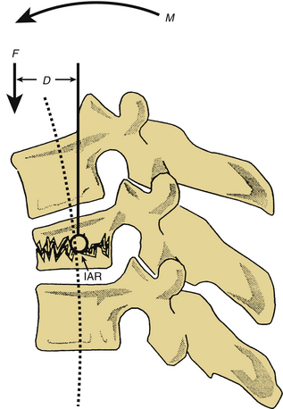
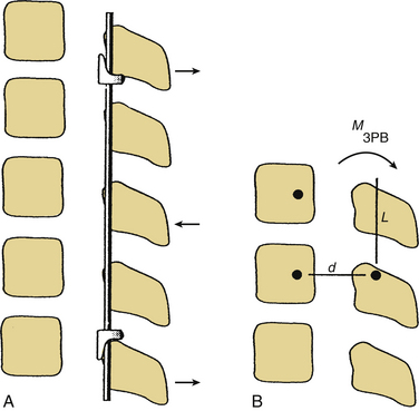
Forces acting on the spine can be broken down into component vectors. A vector is a force that has both a magnitude and a fixed direction in three-dimensional space. A force vector may act directly on a point in space, causing translation (movement in the same plane as the vector). Alternatively, a force vector may act via a lever (moment arm), causing rotation about an axis. When a force vector acts via a moment arm, a bending moment is applied. The axis, or fulcrum, about which this bending moment causes rotation is termed the instantaneous axis of rotation (IAR). The IAR may be defined as the axis about which a given vertebral body rotates when acted on by a bending moment.6,14 In the normal spine, the IAR is located in the region of the dorsal aspect of the vertebral body (middle column of Denis13). The bending moment (M) is defined as the product of the force (F) applied and the moment arm (D) or the perpendicular distance from the IAR (M = F × D). The neutral axis is defined as the longitudinal axis that encompasses the IAR of adjacent vertebral bodies. Forces transmitted along the neutral axis cause no significant bending moment14 (Fig. 150-1).
Newton’s third law of motion, the law of conservation of momentum, states that interactions between objects result in no net change in momentum; thus for every action there is an equal (in magnitude) and opposite (in direction) reaction. In the present context, this implies that the spine (when at rest) exerts forces that are equal in magnitude and opposite in direction to the axial loads and bending moments applied. The ability of the normal spine to resist these forces depends on the material properties of the vertebral bodies and supporting bony, muscular, and ligamentous structures. When spinal instrumentation is applied, the construct may function simply as a replacement for a damaged spinal element (tension band fixation) or may apply forces to the spine in a relatively unusual and complex fashion (three-point bending).6,14
Distraction
Dorsal distraction fixation, usually applied with sublaminar hooks, has been used for short-segment distraction for deformity correction and foraminal stenosis. This mode of application has not found widespread use historically, however, because of a tendency for exaggeration of kyphotic deformity (Fig. 150-2).6 Recently, Zucherman and others have introduced interspinous spacer devices that distract between the spinous processes of the lumbar spine.21 Although these devices relieve symptoms of lumbar stenosis compared with nonsurgical treatment, they do induce kyphosis, which has generally been considered to be a contributor to failed back surgery syndrome and flat back syndrome.22,23
Tension Band Fixation
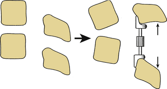
Dorsal compression fixation, applied with hooks, cables, or pedicle screws, is used for tension band fixation in the case of dorsal ligamentous insufficiency. This technique depends on the integrity of the load-supporting capacity of the ventral elements as well as the preservation of the relevant dorsal bony elements. This type of fixation should never be applied without adequate ventral spinal canal decompression. Tension band fixation may be used as a short-segment fixator, since the applied bending moment is independent of construct length (Fig. 150-3). Tension band constructs do not, in general, resist translation and should not be relied on as stand-alone constructs when significant resistance to translation is required. When multiple segments are to be instrumented with this technique, multiple points of fixation should be used to prevent terminal bending moments.6
Three-Point Bending
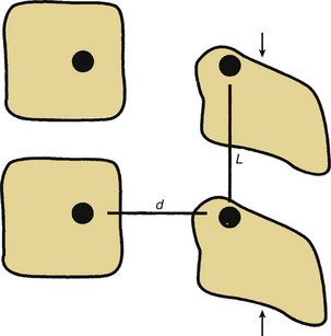
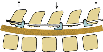
Three-point bending forces are applied when translational forces are applied at both ends of a construct that are equal in magnitude but opposite in direction to a translational force applied to the fulcrum of a pathologic curvature. These constructs are usually applied in a distraction or neutral mode. The prototypical three-point bending construct is the Harrington distraction rod, especially when augmented with sleeves. The application of three-point bending forces depends on the physical contact between the longitudinal member and the fulcrum of the kyphotic deformity. These constructs, when placed dorsally, result in a dorsally directed force at both termini and a ventrally directed force at the fulcrum of the kyphotic curve (Fig. 150-4).6 Three-point bending constructs must, by definition, traverse at least three spinal segments. Because the bending moments applied by a three-point bending implant are proportional to the length of the construct, multiple-segment instrumentation is frequently used to correct significant deformity. Because of the strong dorsally directed forces at the termini of the construct, three-point bending constructs are best applied by using multiple points of fixation. This maximizes the area of contact between the implant and bone. Laminar hooks are ideally designed to resist pull-out forces; however, sublaminar instrumentation placement carries a risk of injury to the neural elements. Pedicle hooks, transverse process hooks, and hook-screw combinations may be used in many cases to avoid sublaminar placement of hooks. A pedicle screw-hook construct at the same level provides substantial pull-out resistance and also contributes to load sharing (see later discussion) and is favored in many cases of significant instability. USI systems allow for the application of these constructs in a neutral mode by using hook “claws,” which are able to engage the lamina without the significant distractive forces required by the Harrington rod system. Use of the claw technique allows for shorter segment fixation, since greater stresses may be borne at the hook-hook-lamina junction.6
Cantilever Beam Constructs
The final mode of application of dorsal universal instrumentation systems is cantilever beam fixation. A cantilever beam is simply a beam supported at one end, such as a balcony or awning support. These constructs are applied by using pedicle screws as the beams. Cantilever beams may be applied in one of three fashions. The great majority that are applied to the thoracic and lumbar spine are fixed-moment arm cantilever beams (Fig. 150-5A). A fixed-moment arm cantilever beam is one in which the pedicle screw is rigidly affixed to the longitudinal member. This type of construct allows for load bearing (when placed in a neutral or distractive mode) or load sharing (when placed in a compressive mode in conjunction with adequate ventral support).
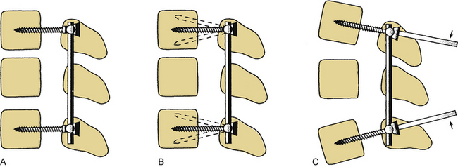
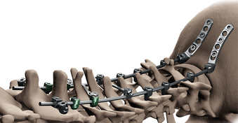
Nonfixed cantilever beam constructs, in which the pedicle screw is not rigidly affixed to the longitudinal member, are rarely used in the thoracic and lumbar spine because of their inability to bear loads (like a hinged awning) and their poor performance as tension band constructs (caused by screw toggling and pull-out) (Fig. 150-5B). In the cervical spine, older lateral mass plate-screw systems are commonly applied nonfixed-moment arm cantilever beam constructs that work well. These systems take advantage of the anatomy of the cervical facet, which tends to resist translation. Due to recent tendencies to combine cervical and thoracic instrumentation systems and the extension of fixation techniques to the occipitocervical and atlantoaxial joints, fixed-moment arm cantilever beam systems have been developed for application in the cervical spine (Fig. 150-6). These systems allow for resistance to translation at C1-2 and seamless combination with thoracolumbar USI systems.24
The final cantilever beam construct is the applied-moment arm cantilever beam. This type of construct allows for the application of flexion or extension forces at the time of implant placement. Using long screws (Schanz type), a bending moment is applied to the spine. Once the desired corrective forces have been applied, the implant is fixed in place (Fig. 150-5C).6 The application of these forces places great stress on the implant, which may result in failure of the implant, particularly if osseous union does not occur in a timely fashion.
Biomechanical Properties of Universal Spinal Implant Systems
All universal spinal implant systems consist of screws, hooks, and longitudinal members. The composition, shape, and size of the implants vary to some extent. However, all conform to the constraints placed on them by the anatomic configuration of the bony spine. Some of the basic properties of the components and the effect that changes in these basic properties (e.g., the particular alloy of stainless steel used in a longitudinal member or the profile of the minor diameter of a screw) have on the performance of a given system are discussed in the following sections.
Metallurgy
USI systems are composed of stainless steel, titanium alloy, or pure titanium. Stainless steel implants are, in general, stronger than similarly sized titanium implants and have excellent corrosion resistance. The most commonly used alloy is 316L stainless steel, which contains 17% chromium, 13% nickel, and 2.25% molybdenum. A newer alloy, 22-13-5 (referring to percentages of chromium, nickel, and manganese, respectively) has even greater strength and surface hardness.25 Stainless steel implants are ferromagnetic and thus interfere with MRI. Furthermore, osteointegration, or the ingrowth of bone into steel screws or rods, does not occur. A final caveat regarding the use of stainless steel is that it should not be used in patients with cutaneous nickel allergies. Dermal patch testing can rule out significant reaction to the alloy if there is a question regarding hypersensitivity.25
Titanium alloys have the advantages of being highly biocompatible and minimally interfering with MRI. The most common titanium alloy is Ti-6-4, a combination of titanium, aluminum, and vanadium. This particular alloy has tensile strength that approaches that of 316L stainless steel. It is quite brittle, however.25 Titanium may also be used in its unalloyed, or “pure,” form.26 Pure titanium is available in several grades (1–4), depending on the amount of impurities found in the metal. The less-pure grades (2–4) have tensile and elastic properties that approach those of 316L stainless steel. Titanium is more resistant to corrosion than steel6 and also allows for osteointegration, both of which should decrease the incidence of implant failure.25
In addition to the composition of the metal used to create a spinal implant, the processes used to forge the metal and the surface characteristics of the implant affect performance. For example, cold working of a metal implant produces a harder, stronger material than does annealing. Also, shot peening, a surface treatment in which the implant is hardened by firing small particles against it, increases fatigue resistance. Any surface irregularity will increase the rate of corrosion of any implant. Finally, metals in implant construction should not be mixed, to avoid creating a galvanic current between the implant components. Such a current could, theoretically, increase the rate of corrosion and weaken the implant.6
Polyetheretherketone
Polyetheretherketone (PEEK) is a carbon-based thermoplastic polymer that maintains stability at temperatures in excess of 300ºC.27 PEEK is biocompatible and inert, with few reports of cutaneous, muscular, or inflammatory reactions.28 Biomechanically, PEEK rods have an elasticity, measured by Young’s modulus, similar to cortical bone, unlike titanium rods, which are much stiffer.29 PEEK rods may also have some biomechanical advantages in terms of resistance to static and fatigue angular displacements compared with their titanium counterparts; however, the clinical significance of this in the setting of a bony fusion is not established.28 Few studies have been performed comparing PEEK and titanium instrumentation; however, potential advantages of PEEK include its radiolucency, load-sharing capacities, and resistance to pedicle fracture given a more favorable bone-screw interface.30
Hook Design
Hooks used for universal instrumentation may be placed in a variety of positions. Laminar hooks may be placed facing rostrally or caudally. Pedicle hooks are placed outside of the spinal canal and face rostrally, abutting the pedicle. Transverse process hooks are placed facing caudally over the transverse processes of the thoracic spine. Manufacturers have responded differently to the multiple locations and orientations of the hooks. Some systems, such as the Texas Scottish Rite Hospital (TSRH) system, provide a wide variety of hooks specially designed for placement at a specific site and with a specific orientation. Other systems, such as the Isola system, use similar hooks for all applications (Fig. 150-7). The choice of the system used depends on surgeon preference. More choices, in terms of hook configuration, require less bone contouring. However, more choices also require a more cumbersome instrumentation set.31
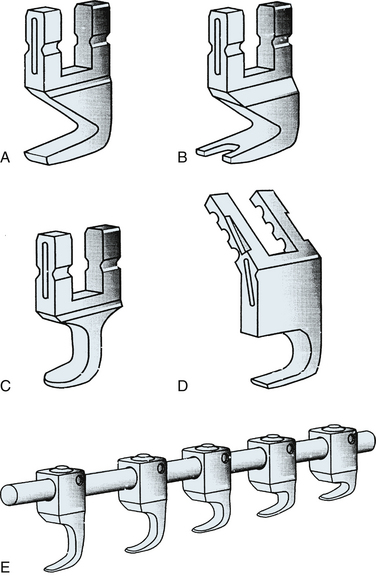
Hooks may be open ended, allowing top loading of the rod onto the hook, or alternatively, they may be closed so that the rod can slide through a circular aperture. Closed hooks are theoretically stronger and should in general be used at the terminus of a construct where applied forces are the greatest. Open-ended hooks are best used at sites of intermediate fixation, within the center of the construct, because of their ease of application.31 In reality, the incidence of hook failure caused by failure of the hook-rod interface is extremely low in modern USI systems.
Pedicle Screws
Pedicle screws are used for fixation of spinal implants when the lamina or transverse processes are not present (after decompression or trauma) or when significant load bearing or resistance to rotation by the implant is desired. Pedicle screw design incorporates several biomechanical principles. The minor diameter of a screw is defined as the minimal (inner) diameter of the screw (base of one thread to the base of the opposite thread). The strength, or resistance to bending and breaking, of a screw is proportional to the third power of its minor diameter. Therefore, small increases in the minor diameter of a screw are associated with large increases in strength. Obviously, the anatomic configuration of the pedicle and the design constraints limit the minor diameter. Because the region of the screw subject to the greatest strain is the screw-plate or screw-rod junction, tapered screws have been developed to maximize strength where it is needed without sacrificing pull-out resistance.25
The pull-out resistance of a screw is related to the amount of bone that can be incorporated between the threads of the screw. The distance between the threads (pitch), major diameter, and thread shape all influence the pull-out resistance of a screw. Osteointegration should significantly increase resistance to screw pull-out. The most important factor in determining screw pull-out resistance is bone quality. Osteopenic bone and low-density medullary bone provide poor purchase for even the best designed screws. Severe osteopenia may be considered a contraindication for screw fixation. Augmentation of pedicles with polymethylmethacrylate or other cements has been described as a means to overcome the effects of osteoporosis; however, caution is advised when applying significant forces to the osteoporotic spine.32,33 A screw diameter should be selected such that the relatively dense cortical bone of the pedicle walls is partially engaged by the threads of the screw to maximize pull-out resistance.
Longitudinal Members
The longitudinal components of USI systems consist of rods or plates. Surface characteristics of the rods vary to maximize component-component junction strength (e.g., the knurled surfaces of Cotrel-Dubousset [CD] rods) and/or implant corrosion resistance (smooth surfaces of the TSRH rods). Two factors that weaken any longitudinal member are stress risers and notching. Stress risers result from the application of focal stress, which usually occurs during contouring of the rods or plates. Notching is an injury to the surface of an implant that may result in significant alterations of structural integrity. A 1% notch (e.g., a 3.6-mm rod with a 36-μm-deep notch) reduces fatigue resistance of 316L stainless steel wire by 63%.34 Titanium is known to be especially sensitive to the effects of notching.6,35
Component-Component Junctions
USI systems use different mechanisms for component-component junctions. The mechanism of engagement and the surface characteristics of the implants affect the durability and strength of the construct as a whole. The most commonly used mechanisms for attaching component hooks and screws to longitudinal members are the three-point shear clamp, lock screw connectors, circumferential grip connectors, constrained and semiconstrained screw-plate connectors, and semiconstrained hook-rod connectors.6 Three-point shear clamp connectors use a three-point bending force applied to the longitudinal member (rod) to tightly approximate the components. The majority of TSRH connectors are of this type. A lock screw connector uses a screw to drive the rod into a contoured bed, as with the Isola V groove hollow ground system. Tangential application of the screw appears to have some mechanical advantage.6
Circumferential grip connectors provide both halves of a pincer to provide truly circumferential force application (e.g., Synthes locking screw-plate connector) or only half of the pincer (Isola VHG).6 Constrained bolt-plate connectors do not allow toggling of the screw or hook at the component-component junction. The Steffee plate-pedicle screw connector is an example of this type of connection. The only example of a semiconstrained connector (that allows movement in at least one plane) used in the thoracic or lumbar spine is the Harrington rod-hook connection, which allows for rotation and some toggling of the hook about the rod.6
Surface characteristics of the component-component junction are important. Friction enhancers, such as knurled surfaces, radial spokes or grooves, or a grid pattern, increase friction between the components. Knurled surfaces should not be mixed with smooth surfaces, because this can result in poor surface contact.
Polyaxial Pedicle Screws
Traditionally, pedicle screw heads were fixed, necessitating adjustments to the depth of screw insertion so as to accommodate rod placement. Repositioning of pedicle screws, without increasing the diameter of the screw, decreases its purchase strength.36A polyaxial screw is designed with the screw head enclosed on a housing unit that allows for ball-joint motion of the screw head (Fig. 150-8).Variable-head screws minimize repositioning of pedicle screws and contouring of the rods, conferring a theoretical advantage to pull-out strength of pedicle screws and avoidance of “notching” due to contouring. Polyaxial screws do not significantly decrease construct stiffness, and there is a suggestion of increased resistance to torque conferred by better purchase of the intervertebral rod.37 Biomechanical testing shows that the first failure point of polyaxial screws is the head-screw interface.38
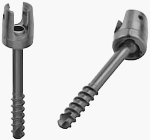
FIGURE 150-8 Polyaxial pedicle screws. Note that the screw head is mounted to allow for ball-joint maneuvering.
(Images provided by Medtronic Sofamor Danek USA, Memphis, TN.)
Technical Aspects of Implant Application
USI placement techniques have been described.6,7,31,39 What follows is a brief overview of the techniques used for the placement of dorsal spinal instrumentation.
Pedicle Screw Insertion
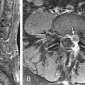
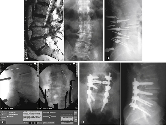
The pedicle is the strongest portion of the vertebra. It consists largely of cortical bone. The transverse width of the pedicle is the limiting factor in terms of screw size and may be determined by preoperative CT. The transverse pedicle angle increases from near 0 degrees (straight dorsal-ventral) at L1 to nearly 30 degrees (dorsolateral to ventromedial) at L5. The sagittal angle of the pedicle also varies somewhat, but in a narrower range (5 degrees craniocaudal at L1 to 15 degrees at L5).14,39,40 Preoperative radiographic studies aid in the determination of optimal screw placement angles. Alternatively, recent advances in frameless stereotaxy allow facile comparison of surgical anatomy with preoperative axial imaging studies. A caveat to the use of these systems is that the images displayed are not real time. Therefore, the quality of the information provided to the surgeon depends completely on the accuracy of registration of the vertebral body involved. Alternatively, fluoroscopy or fluoroscopy-based frameless stereotactic systems may be used to provide feedback to the surgeon regarding hidden anatomy. The main limitation to the fluoroscopy-based frameless stereotactic systems is the quality of the source images. The use of frameless stereotaxy has been reported to improve the accuracy of pedicle screw placement in the lumbar and thoracic spine.41–43 The use of such systems does not appear to degrade the fluoroscopic information and may in fact provide better feedback than live fluoroscopy because of the ability to use multiplanar imaging44 (Fig. 150-9). Recent advances in imaging technology have allowed the use of real-time axial imaging in the operating room. These systems provide the advantages of axial imaging with real-time image acquisition.45,46 Depending on surgical technique, the use of such systems may or may not be associated with improved outcomes. Intraoperative electrophysiologic stimulation has been used by some investigators for the purpose of increased sensitivity to cortical violation during pedicle preparation.47,48 Although such systems can indicate a pedicle breach, no evidence has been reported that clinical outcomes are favorably influenced by the use of such systems.49
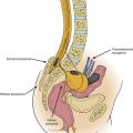
The dorsal aspect of the lumbar pedicle is localized by using the junction of two lines. The first line is a straight rostrocaudal line drawn along the lateral border of the superior articular facet. The second line is a transverse line through the center of the transverse process (Fig. 150-10). The lateral aspect of the pedicle may be palpated with a dissector placed over the rostral border of the transverse process, and, when practical, the medial aspect of the pedicle may be exposed by laminectomy or laminotomy. The screw entrance site (dorsal aspect of the pedicle) is decorticated with a drill or rongeur, and the pedicle is probed with a blunt-tipped pin or small curet. Intraoperative radiographs are used to check the accuracy of pin placement and trajectory. Once adequate placement of the pins has been confirmed, the pins are removed and the holes prepared for screw placement. Alternatively, the pedicles may be cannulated with a 2.5-mm drill. This technique is largely used in conjunction with a frameless stereotactic system or with real-time fluoroscopy. Gentle pressure and a slight “tapping” motion help to keep the drill bit within the confines of the pedicle. This technique is especially useful in sclerotic pedicles (congenital spondylolisthesis) or in very small pedicles (e.g., in the thoracic spine, see later discussion). Hole locations are marked with radiopaque markers and verified with intraoperative radiographs or fluoroscopy.
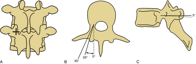
FIGURE 150-10 Pedicle screw placement. A, The entrance point for pedicle screw placement is at the junction of the rostrocaudal lateral facet line and the transverse midtransverse process line. B, Axial representations of pedicle screw placement in the L4 and L5 vertebrae. Note the difference in the angle of placement with the L4 screw oriented at a 20-degree angle from the sagittal plane and the L5 screw oriented at a near 30-degree angle from the sagittal plane.12,14 C, Sagittal view of pedicle screw placement in L4 and L5. Differences in the sagittal angulation of the pedicles of the lumbar vertebrae are not as pronounced as in the axial plane. Note the slight difference in the angulation with the L4 screw placed parallel to the axial plane and the L5 screw placed at a 3-degree angle with respect to the axial plane.12,14
(Copyright University of New Mexico, Division of Neurosurgery.)
Reliable anatomic landmarks used for the placement of thoracic pedicle screws probably do not exist. Unfortunately, there is a substantial amount of variability in pedicle location, size, and angle between individuals and between levels in the same individual.50 As such, pedicle cortex violation is relatively common with blind insertion. One such series reported a 47% rate of pedicle breach.51 Special aiming devices have been manufactured but have not been subject to critical review.52 The use of frameless stereotactic techniques has improved accuracy of screw placement in several series.41–43 An alternative technique, the performance of small laminotomies to directly palpate the pedicle for the placement of thoracic pedicle screws, has also been described as improving accuracy. The surgeon should choose the technique that works best in his or her hands and become a master at that particular technique.
Holes are tapped with successively larger taps until a desired diameter is reached. The walls of the pedicle should be palpated from within after each tap to verify the integrity of the cortical bone. Screws should be placed with as much lateral-to-medial angulation as possible so as to maximize the beneficial effects of triangulation on screw pull-out and parallelograming if cross-links are to be applied (see later discussion).6 Screw placement lateral to the pedicle may allow for increased triangulation without significantly degrading pull-out resistance. We reserve this technique for salvage following pedicle stripping or fracture. Screw length should be selected such that the ventral two thirds of the vertebral body is engaged. Because of the constrained linkages between the screws and the longitudinal member in all thoracolumbar USI systems, no significant advantage is gained by penetration of the ventral cortex. A final intraoperative radiograph is obtained before linkage to the longitudinal member.
Laminar Hook Insertion
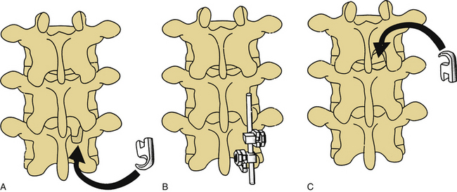
Laminar hooks are designed to be placed under the lamina, facing either rostrally or caudally. The use of laminar hooks in the lumbar and sacral spine is universally accepted, whereas use of such hooks above the level of the conus medullaris is more controversial. Preoperative imaging studies are useful for determining the adequacy of the spinal canal for sublaminar hook placement. If a relative stenosis exists at a particular level, that level should be avoided and fixation obtained at another level or by another means. In all cases, care must be taken to prevent the hooks from encroaching on neural elements. Laminotomies are performed, removing the caudal portion of the lamina above and the rostral portion of the lamina below the level of hook application (Fig. 150-11). The ligamentum flavum is removed, and in some cases, medial facetectomies are performed. A laminar tester is used to verify the adequacy of the sublaminar dissection. The largest hook that can be placed at a given level should be selected to maximize the bone-implant junction. It is often possible to “stagger” hooks from side to side so as to avoid placing two hooks under the same lamina. The hook must closely appose the laminar surface to avoid encroachment into the spinal canal. If an appropriately contoured hook is not available, the lamina should be contoured for an exact fit. Once a hook is placed, it should be compressed against its lamina to prevent migration into the spinal canal. Special care must be taken when hooks are used as intermediate points of fixation with three-point bending constructs (Fig. 150-12) because the hooks may be driven into the spinal canal by the application of such forces if they are not tightly apposed to their respective laminae.6,31
Pedicle Hooks
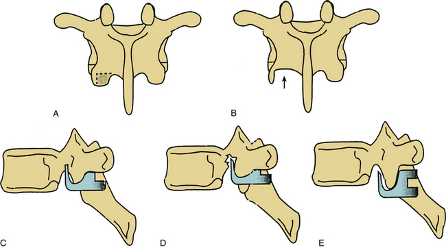
Thoracic pedicle hooks are placed between the superior and inferior articulating surfaces of the facet. The caudal portion of the inferior articular process is removed by using a drill or osteotome. The amount of bone removed is critical, because if too little bone is removed, the hook does not engage the facet (Fig. 150-13). Transverse migration may not be prevented (with bifid hooks). Conversely, if too much bone is removed, the hook may cut into the pedicle, thus decreasing the strength of the pedicle/inferior articulating process connection. Frequent trial placements of the hook may be helpful in determining the optimal hook size and amount of bone removal necessary for good purchase.6,31
Transverse Process Hook Insertion
The transverse processes may be used for hook purchase in the thoracic spine. These hooks are usually placed facing caudally in conjunction with a rostrally facing pedicle hook. The costotransverse ligament is stripped off the transverse process by using a specially designed stripping tool, and the hook is placed over the rostral border of the transverse process. Offset hooks are frequently useful, as there is a substantial distance between the transverse process hook and pedicle hook fixation points in the coronal plane. Use of these hooks at the thoracolumbar junction is limited, since the transverse processes of T11 and T12 are usually too small to provide substantial purchase strength.31
Cross-Fixation
Cross-fixation increases the stability of a construct by preventing rotation or translation (coronal or sagittal) of the longitudinal members with respect to each other. The torsional stability of an implant is increased substantially by the use of a single cross-fixator (44%) and further increased with the use of two cross-fixators (an additional 26% gain in stability).53 Screw pull-out resistance is also markedly improved with the use of rigid cross-links combined with toeing in of the screws. A lateral translational deformity caused by “parallelograming” is resisted by the use of cross-fixators.6 Cross-fixators should be placed at the junctions of the middle third of the implant with the rostral and caudal thirds. No significant biomechanical advantage is gained by the use of more than two cross-fixators. Although some USI cross-fixators are easier to apply than others, it is important, in general, not to mix sets or metals because of the potential for galvanically enhanced electrolytic corrosion.
Complication Avoidance and Management
The use of dorsal thoracic and lumbar USI systems is associated with a number of potential complications. The most significant short-term complications relate to loss of bony purchase, immediate implant failure, cerebrospinal fluid (CSF) fistula formation, and neural element injury.26,54–56 Techniques for the prevention and management of these types of events are discussed in the following sections.
Complications of Hook Fixation
Hooks placed in the spinal canal (laminar hooks) must tightly appose the ventral surface of the lamina to prevent neurologic injury. The use of such hooks above the level of the conus medullaris is possible but certainly carries with it a higher risk for neurologic injury. Great care must be taken with the use of laminar hooks as intermediate points of fixation in a three-point bending implant. The ventrally directed force at the center of such an implant may drive the hook blade into the spinal canal (see Fig. 150-12).
Pedicle hooks that are placed outside of the spinal canal may migrate during implant manipulation and may encroach on the spinal canal or neural foramina. Bifid hooks may lessen the risks of this complication. It is important to remove an appropriate amount of bone from the inferior articulating process of the facet before pedicle hook placement. Inadequate or overzealous bone removal may lead to malposition of pedicle hooks in the sagittal plane, which may lead to hook loosening or to pedicle fracture. Frequent use of hook testers will help to determine the correct amount of bone to be removed from the inferior articular process of the facet (see Fig. 150-13).
Complications of Transpedicular Fixation
Complications of pedicle fixation result from technical difficulties with implant application and from improper preoperative planning. The most common technical error in the placement of pedicle screws is malpositioning of the screw, resulting in pedicle fracture.26,55,57,58 Pedicle fracture may occur if the pedicle screw entry site is inappropriate, the angle of screw placement is off, or the screw selected is too large in diameter. Depending on the location of the pedicle fracture, the consequence may be loss of purchase, CSF fistula, or neural injury. Preoperative studies must be obtained and reviewed to determine the correct size of the screw and angle of insertion (sagittal as well as coronal). Although intraoperative radiography is helpful, screw malposition in the axial plane may still occur despite radiographically acceptable positioning in the operating room.58 The use of intraoperative electrophysiologic monitoring47,48,59 and frameless stereotaxy may provide improved feedback to the surgeon for more accurate screw placement.41–43
We emphasize again that pedicle fracture can result in such sequelae as loss of purchase, CSF fistula, and neural injury. In the instance of loss of purchase, incorporation of an additional spinal segment may be necessary. CSF fistula should be repaired primarily when possible. When impossible or impractical, the pedicle defect may be packed with hemostatic gelatin (Gelfoam) soaked in thrombin or fibrin glue in an attempt to minimize CSF egress. Screws that are known to have perforated the medial cortex of the pedicle should be repositioned immediately. Screws that are found to be misplaced at the time of follow-up study may be well tolerated by the patient, as there may be up to 4 mm of a “safe” zone medial to the lumbar pedicle cortex.60 This safe zone may not exist in the thoracic spine.50 Patients with medial cortex fractures may develop late erosion of the screw threads into the neural foramina or spinal canal, which may cause nerve root injury. If the patient is symptomatic, such screws should be removed. Nerve root irritation may also result from caudal breaches of the pedicle cortex, where the exiting root is vulnerable to impingement or lateral pedicle breach, where the lumbosacral plexus may be irritated. Finally, perforation of the ventral cortex may result in significant vascular or visceral injury.
Postoperative complications related directly to implant failure may be avoided to some extent through proper preoperative planning and construct design. For example, application of three-point bending constructs should usually not be attempted with single screws as the terminal fixators. Although screw pull-out resistance may be maximized by the toeing-in of the screws (triangulation) and the use of cross-fixators, hooks still provide a greater resistance to translational forces. Similarly, when significant corrective forces are required, a sufficiently long construct should be used so as to avoid overly stressing the implant-bone or screw-rod junction.22 Dorsal instrumentation cannot be relied on to replace the ventral load-bearing capacity of the spine, and attempts to do so are likely to fail.
Pedicle screw fracture may occur at the time of implant application, during attempted removal of instrumentation after fusion, or spontaneously in the months to years following implantation. The decision to remove implants in patients with persistent back pain after thoracic or lumbar fusion must be made on an individual basis. When there is evidence of implant failure, such as a broken rod or screw, medicolegal implications may prompt the surgeon to attempt removal. If a screw is fractured such that it cannot be removed by using standard techniques, a screw extractor kit may be used to remove distal screw fragments. A carbide-tipped drill is used to drill a hole in the screw fragment, and then a left-handed tap is inserted into the hole (“Easy-Out”). As the left-handed threads of the tap engage the screw, the screw begins to back out. Copious irrigation is required to remove fragments of metal, which will obscure postoperative imaging. We recommend using a hand drill instead of a pneumatic drill, as even a slight deviation from a coaxial trajectory may result in a violent removal with inadvertent pedicle fracture.
Bennett G.L. Materials and materials testing. In: Benzel E.C., editor. Neurosurgical topics: spinal instrumentation. Park Ridge, IL: American Association of Neurological Surgeons; 1994:31-46.
Benzel E.C. Construct design. In: Benzel E.C., editor. Neurosurgical topics: spinal instrumentation. Park Ridge, IL: American Association of Neurological Surgeons; 1994:239-256.
Benzel E.C. Biomechanics of spine stabilization: principles and clinical practice. New York: McGraw-Hill; 1995.
Chozick B.S., Toselli R. Complications of spinal instrumentation. In: Benzel E.C., editor. Neurosurgical topics: spinal instrumentation. Park Ridge, IL: American Association of Neurological Surgeons; 1994:257-274.
Stillerman C.B., Gruen J.P. Universal spinal instrumentation. In: Benzel E.C., editor. Neurosurgical topics: spinal instrumentation. Park Ridge, IL: American Association of Neurological Surgeons; 1994:147-174.
White A.A., Panjabi M.M. Clinical biomechanics of the spine, ed 2, Philadelphia: Lippincott-Raven, 1990.
1. Hadra B.E. The classic wiring of the vertebrae as a means of immobilization in fracture and Pott’s disease (reprinted from original). Clin Orthop Relat Res. 1975;112:4-8.
2. Lange F. The classic support for the spondylitic spine by means of buried steel bars attached to the vertebrae (reprinted from original). Clin Orthop Relat Res. 1986;203:3-6.
3. Harrington P.R. Treatment of scoliosis: correction and internal fixation by spine instrumentation. J Bone Joint Surg [Am]. 1962;44:591-610.
4. Benzel E.C., Ball P.A. History of spinal instrumentation. In: Benzel E.C., editor. Neurosurgical topics: spinal instrumentation. Park Ridge, IL: American Association of Neurological Surgeons; 1994:3-10.
5. Luque E.R. The anatomic basis and development of segmental spinal instrumentation. Spine. 1982;7:256-259.
6. Benzel E.C. Biomechanics of spine stabilization: principles and clinical practice. New York: McGraw-Hill; 1995.
7. Roy-Camille R., Saillant G., Mazel C. Internal fixation of the lumbar spine with pedicle screw plating. Clin Orthop Relat Res. 1986;203:7-17.
8. Cotrel Y., Dubousset J., Guillaumat M. New universal instrumentation in spinal surgery. Clin Orthop Relat Res. 1988;227:10.
9. Zdeblick T.A. A prospective, randomized study of lumbar fusion. Preliminary results. Spine (Phila Pa 1976). 1993;18:983-991.
10. Mardjetko S.M., Connolly P.J., Shott S. Degenerative lumbar spondylolisthesis. A meta-analysis of the literature 1970–1993. Spine (Phila Pa 1976). 1994;198:2256-2265.
11. Jacobs R.R., Asher M.A., Snider R.K. Thoracolumbar spine injuries: a comparative study of recumbent and operative treatment in 100 patients. Spine (Phila Pa 1976). 1980;5:463.
12. Willen J., Lindahl S., Nordwall A. Unstable thoracolumbar fractures: a comparative clinical study of conservative treatment and Harrington instrumentation. Spine (Phila Pa 1976). 1985;10:111.
13. Denis F. The three column spine and its significance in the classification of acute thoracolumbar spine injuries. Spine (Phila Pa 1976). 1983;8:817-837.
14. White A.A., Panjabi M.M. Clinical biomechanics of the spine, ed 2, Philadelphia: Lippincott-Raven, 1990.
15. Resnick D.K., Choudhri T.F., Dailey A.T., et al. Guidelines for the performance of fusion procedures for degenerative disease of the lumbar spine. Part 7: Intractable low-back pain without stenosis or spondylolisthesis. J Neurosurg Spine. 2005;2:670-672.
16. Resnick D.K., Choudhri T.F., Dailey A.T., et al. Guidelines for the performance of fusion procedures for degenerative disease of the lumbar spine. Part 9: Fusion in patients with stenosis and spondylolisthesis. J Neurosurg Spine. 2005;2:679-685.
17. Chou R., Baisden J., Carragee E.J., et al. Surgery for low back pain: a review of the evidence for an American Pain Society Clinical Practice Guideline. Spine (Phila Pa 1976). 2009;34(10):1094-1109.
18. Frymoyer J.W., Selby D.K. Segmental instability: rationale for treatment. Spine (Phila Pa 1976). 1985;10:280-286.
19. Sonntag V.K.H., Marciano F.F. Is fusion indicated for lumbar spinal disorders? Spine (Phila Pa 1976). 1995;20:1388-1428.
20. Weinstein J.N., Lurie J.D., Olson P.R., et al. United States’ trends and regional variations in lumbar spine surgery: 1992–2003. Spine (Phila Pa 1976). 2006;31(23):2702-2714.
21. Zucherman J.F., Hsu K.Y., Hartjen C.A., et al. A multicenter, prospective, randomized trial evaluating the X STOP interspinous process decompression system for the treatment of neurogenic intermittent claudication: two-year follow-up results. Spine (Phila Pa 1976). 2005;30(12):1351-1358.
22. Lindsey D.P., Swanson K.E., Fuchs P., et al. The effects of an interspinous implant on the kinematics of the instrumented and adjacent levels in the lumbar spine. Spine (Phila Pa 1976). 2003;28(19):2192-2197.
23. Jagannathan J., Sansur C.A., Shaffrey C.I. Iatrogenic spinal deformity. Neurosurgery. 2008;63:104-116.
24. Lapsiwala S., Benzel E. Surgical management of cervical myelopathy dealing with the cervical-thoracic junction. Spine (Phila Pa 1976). 2006;6:268S-273S.
25. Bennett G.L. Materials and materials testing. In: Benzel E.C., editor. Neurosurgical topics: spinal instrumentation. Park Ridge, IL: American Association of Neurological Surgeons; 1994:31-46.
26. Chozick B.S., Toselli R. Complications of spinal instrumentation. In: Benzel E.C., editor. Neurosurgical topics: spinal instrumentation. Park Ridge, IL: American Association of Neurological Surgeons; 1994:257-274.
27. Kurtz S.M., Devine J.N. PEEK biomaterials in trauma, orthopedic, and spinal implants. Biomaterials. 2007;28:4845-4869.
28. Ponnappan R.K., Serhan H., Zarda B., et al. Biomechanical evaluation and comparison of polyetheretherketone rod system to traditional titanium rod fixation. Spine J. 2009;9:263-267.
29. Moon S., Ingalhalikar A., Highsmith J., Vaccaro A. Biomechanical rigidity of an all-polyetheretherketone anterior thoracolumbar spinal reconstruction construct: an in vitro corpectomy model. Spine J. 2009;9:330-335.
30. Highsmith J., Tumialan L., Rodts G. Flexible rods and the case for dynamic stabilization. Neurosurg Focus. 2007;22:1-5.
31. Stillerman C.B., Gruen J.P. Universal spinal instrumentation. In: Benzel E.C., editor. Neurosurgical topics: spinal instrumentation. Park Ridge, IL: American Association of Neurological Surgeons; 1994:147-174.
32. Oner F.C., Verlaan J.J., Verbout A.J., Dhert W.J. Cement augmentation techniques in traumatic thoracolumbar spine fractures. Spine (Phila Pa 1976). 2006;31:S89-S95.
33. Tan J.S., Singh S., Zhu Q.A., et al. The effect of cement augmentation and extension of posterior instrumentation on stabilization and adjacent level effects in the elderly spine. Spine (Phila Pa 1976). 2008;33:2728-2740.
34. Oh I., Sander T.W., Treharne R.W. The fatigue resistance of orthopaedic wire. Clin Orthop Relat Res. 1985;192:228-236.
35. Scuderi GJ, Greenberg SS, Latta LL, et-al.: A biomechanical evaluation of MRI compatible wire for use in cervical spine fixation. Presented at the Cervical Spine Research Society Meeting, Palm Springs, FL, 1992.
36. Polly D.W.Jr., Orchowski J.R., Ellenbogen R.G. Revision pedicle screws. Bigger, longer shims—what is best? Spine (Phila Pa 1976). 1998;23:1374-1379.
37. Sheard M.F., Davies M.R., Abayan A., et al. Effects of polyaxial pedicle screws on lumbar construct rigidity. J Spinal Disord. 2002;15:233-236.
38. Fogel G.R., Reitman C.A., Liu W., Esses S.I. Physical characteristics of polyaxial-headed pedicle screws and biomechanical comparison of load with their failure. Spine (Phila Pa 1976). 2003;28:470-473.
39. Benzel E.C., Construct design, Benzel E.C. Neurosurgical topics: spinal instrumentation. Park Ridge, IL: American Association of Neurological Surgeons. 1994:239-256.
40. Krag M.H., Weaver D.L., Beynnon B.D. Morphometry of the thoracic and lumbar spine related to transpedicular screw placement for surgical spinal fixation. Spine (Phila Pa 1976). 1988;13:27-32.
41. Amiot L.P., Lang K., Putzier M., et al. Comparative results between conventional and computer assisted pedicle screw installation in the thoracic, lumbar, and sacral spine. Spine (Phila Pa 1976). 2000;25:606-614.
42. Kim K.D., Johnson P.J., Bloch B.S., Masciopinto J.E. Computer assisted thoracic pedicle screw placement: an in vitro feasibility study. Spine (Phila Pa 1976). 2001;26:360-364.
43. Youkilis A.S., Quint D.J., McGillicuddy J.E., Papadopolous S.M. Stereotactic navigation for placement of pedicle screws in the thoracic spine. Neurosurgery. 2001;48:771-778.
44. Resnick D.K. Comparison between virtual fluoroscopy and fluoroscopy for the placement of lumbar pedicle screws. J Spinal Disord. 2003;16:254-260.
45. Kim K.D., Johnson J.P., Babbitz J.D. Image-guided thoracic pedicle screw placement: a technical study in cadavers and preliminary clinical experience. Neurosurg Focus. 2001;10:E2.
46. Ito Y., Sugimoto Y., Tomioka M., et al. Clinical accuracy of 3D fluoroscopy-assisted cervical pedicle screw insertion. J Neurosurg Spine. 2008;9:450-453.
47. Darden B.V., Hatley M., Owen J.H. A comparison of impedance and EMG procedures in detecting the presence of pedicle wall breakthrough. J Neurosurg. 1997;86:414A.
48. Rose B., Welch W.C., Balzer J.R., Jacobs G.B. Persistently electrified pedicle stimulation instruments (PEPSI) in spinal instrumentation. Spine (Phila Pa 1976). 1997;22:334-343.
49. Resnick D.K., Choudhri T.F., Dailey A.T., et al. Guidelines for the performance of fusion procedures for degenerative disease of the lumbar spine. Part 15: Electrophysiological monitoring and lumbar fusion. J Neurosurg Spine. 2005;2:725-732.
50. Ugur H.C., Attar A., Uz A., et al. Thoracic pedicle: surgical anatomic evaluation and relations. J Spinal Disord. 2001;14:39-45.
51. Belmont P.J.Jr., Klemme W.R., Dhawan A., Polly D.W.Jr. in vivo accuracy of thoracic pedicle screws. Spine (Phila Pa 1976). 2001;26:2340-2346.
52. Jang J.S., Lee W.B., Yuan H.A. Use of a guide device to place pedicle screws in the thoracic spine: a cadaveric study. Technical note. J Neurosurg. 2001;94(suppl 2):328-333.
53. Dick J.C., Zdeblick T.A., Bartel B.D., Kunz D.N. Mechanical evaluation of cross-link designs in rigid pedicle screw systems. Spine (Phila Pa 1976). 1997;22:370-373.
54. West J.L.III, Ogilvie J.W., Bradford D.S. Complications of the variable screw plate pedicle screw fixation. Spine (Phila Pa 1976). 1991;16:576-579.
55. Davne S.H., Myers D.L. Complications of lumbar spinal fusion with transpedicular instrumentation. Spine (Phila Pa 1976). 1992;17:S184-S189.
56. Ohlin A., Karlsson M., Duppe H., et al. Complications after transpedicular stabilization of the spine. Spine (Phila Pa 1976). 1994;19:2774-2779.
57. Esses S.I., Sachs B.L., Dreyzin V. Complications associated with the technique of pedicle screw fixation. A selected survey of ABS members. Spine. 1993;18:2231-2238.
58. Farber G.L., Place H.M., Mazur R.A., et al. Accuracy of pedicle screw placement in lumbar fusions by plain radiographs and computed tomography. Spine (Phila Pa 1976). 1995;20:1494-1499.
59. Reidy D.P., Houlden D., Nolan P.C., et al. Evaluation of electromyographic monitoring during insertion of thoracic pedicle screws. J Bone Joint Surg [Br]. 2001;83:1009-1014.
60. Gertzbein S.D., Robbins S.E. Accuracy of pedicle screw placement in vivo. Spine (Phila Pa 1976). 1990;15:11-14.