[level-membership-for-anesthesiology-category]
Chapter 6 Airway management equipment
Standards, techniques (and fashions) in airway management have changed considerably over the last two decades. Although the most basic principle of anaesthesia is the maintenance of a patent airway aimed at providing adequate oxygenation and ventilation, the range of devices and products used has seen major changes especially in the focus of the designs. Of the developments in the last decade several are notable.
Numerous alternatives to the LMA have since been developed. These devices which sit outside the larynx and aim to provide a gas-tight seal are now generally referred to simply as supraglottic airways or SADs (supraglottic airway devices): the term extraglottic airway is more anatomically accurate but is not widely used.1 The number and variety of SAD designs have expanded dramatically in the last few years with the result that there are numerous products that vary considerably in materials and performance. Many of these are single-patient use laryngeal masks designed to compete for the market share of the original LMA. Nonetheless several newer SADs offer genuine advances in versatility, efficacy and safety.
Finally, overlying all the above considerations; concern about the transmission of infective agents, particularly those responsible for variant Creutzfeldt–Jakob disease (vCJD), has been the apparent driving force behind an increasing trend towards reliance on single-use airway devices. This trend, whether based on science or not (of which more later) has meant that the majority of airway devices now being developed are at least in part single-use. Production and material costs and hence price, as well as storage and stocking issues, are ultimately more significant considerations for single-use items and this is already affecting the range and quality of equipment available in many hospitals.
Fundamentals
The fundamental principle of airway management during general anaesthesia is that:
1. a clear airway must be established and maintained allowing free passage of gasses to and from the patient’s lungs. Failure to do this is likely to lead to collapse of the airway at pharyngeal or laryngeal level. Without intervention airway obstruction is inevitable and if not correctly managed, will be followed within minutes by hypoxia, brain damage and death.
Materials used in airway devices
Plastics
The most common plastics are polyethylene and polyvinyl chloride (PVC). Polyethylene is cheap, fairly pliable, non-allergenic and can be moulded easily. It is ideal for breathing hoses, connectors and hypodermic syringes but not for the manufacture of reusable items as it will not withstand autoclaving and components may deform with repeated use. It is unsuitable for tracheal tubes (see below) as other materials cannot be easily welded or glued to its surface (e.g. cuffs). For this purpose, PVC is more suitable. PVC is brittle on its own but can be made in varying degrees of softness by the addition of plasticiszers (see below). Concerns have been raised in some areas about potentially toxic chemicals in PVC called phthalates and the potential production of both phthalates and dioxins when PVC is disposed of or incinerated.2
Materials used in tracheal tube construction are described in more detail below (p.156)
Artificial airways
Terminology
The term airway (or anatomical airway) will be used to describe the air passages within the subject, including and beyond the nasal and oral openings. The term distal refers to the part of the airway or device furthest into the subject’s airway and the term proximal to the part emerging or closest to the mouth or nose. Artificial airway then is any device that aims to maintain patency of any of the air passages. Artificial airways may be:
• simple airway adjuncts, such as the oropharyngeal and the nasopharyngeal airways. These may not be sufficient to maintain the patency of the airway on their own and may require the patient’s jaw to be supported as well. Although these are strictly speaking supraglottic devices in that their distal orifice lies above the glottis, in general usage the term SAD is not used to encompass or imply these simple airways.
• supraglottic airway devices (SAD) such as the laryngeal mask airway (LMA) and many others which aim to maintain patency of the airway on their own
• infraglottic devices, which are airway devices whose distal part lies below the glottis. Therefore they include all tracheal and tracheostomy tubes, jet ventilation catheters and cannulae, and bronchial blockers. It is a lesser used term.
Simple airway adjuncts
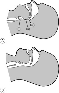
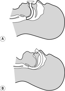
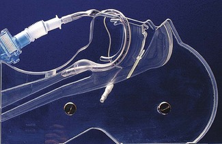
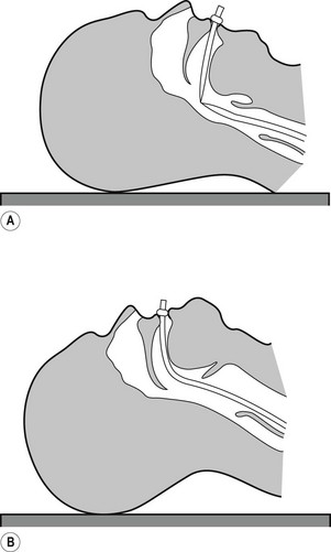
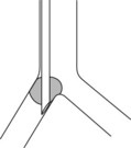
The maintenance of a clear airway in an anaesthetized patient can often be achieved by a simple elevation of the jaw (jaw thrust) and/or extension of the head on the cervical spine. These movements tend to separate the tongue, epiglottis and soft palate from one another and away from the posterior pharyngeal wall (Fig. 6.1). However, in many patients maintenance of the airway in this manner is either ineffective or impractical for surgery. Patients with anatomical reasons for such manoeuvres to fail include those whose ‘pharyngeal spaces’ are absolutely or relatively small (e.g. a large tongue, small lower jaw, large diameter neck, obesity and also those with large adenoid or palatine tonsils). In such patients the obstruction must be relieved and the easiest way to achieve this is by inserting a device that separates these structures and thus creates an artificial airway. These airway adjuncts may be inserted via the mouth (oropharyngeal airway) or via the nose (nasopharyngeal airway) (Fig. 6.2).
Oropharyngeal airway
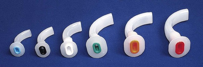
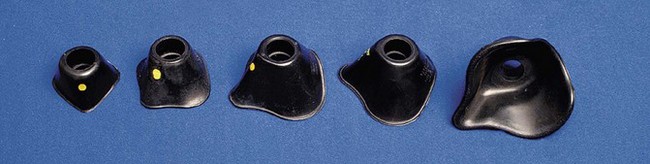
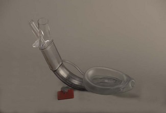
These devices are shaped to emulate and so restore the space present in the pharynx during consciousness by pushing the tongue and epiglottis away from the posterior pharyngeal wall. Oropharyngeal airways are usually oval-shaped, occasionally circular, in cross-section and are produced in varying lengths and diameters to suit different patient sizes from premature neonate to large adult. The proximal end has a flange to limit the depth of insertion and prevent its loss into the pharynx. Devices are sufficiently rigid to prevent collapse should the patient bite down and indeed they may be used as a ‘bite block’ in an intubated patient (to prevent airway obstruction as a result of the tracheal tube being obstructed by biting). When inserted, the distal end should lie at the posterior of the tongue but above the epiglottis. Insertion too deep may in itself lead to airway obstruction either by mechanically pushing the epiglottis back or by irritating the sensitive laryngeal inlet leading to laryngospasm. There is a standard colour and number coding for size. The most popular oropharyngeal airway type is the Guedel pattern (Fig. 6.3). To select the correct size of Guedel airway, the distance from the flange to the distal tip of the airway should be about the same as from the patient’s lips to the tragus of the ear.
Complications
Oropharyngeal airways for flexible endoscopic oral intubation
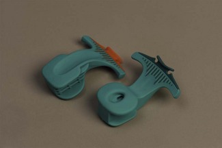
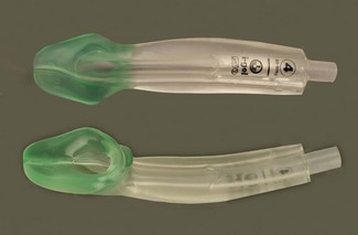
A number of airways have been devised to assist oral intubation. When used to aid flexible endoscopic intubation they serve to deliver the endoscope behind the tongue, and as close to the larynx as possible, ideally having bypassed any secretions. Their shapes are broadly similar to the Guedel airway but often describing a fuller curvature along the length and with a more circular cross-section (Fig. 6.4).
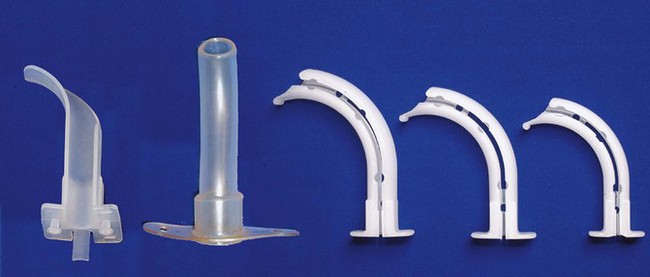
The Berman airway (originally designed to assist blind oral intubation and pharyngeal suction), like the VBM and Ovassapian (not pictured) airways is open along one side. These devices when used for endoscopic intubation are removed before passage of the tracheal tube. The fully enclosed Optosafe airway has a large enough diameter to accommodate a tracheal tube.
The airways also act as a ‘bite block’ preventing damage to expensive fingers or delicate endoscopes (see also: Flexible endoscopes, conduit airways). This purpose is better served by the use of a dedicated bite block such as the BreatheSafe (Fig. 6.5) which more resembles a dental prop and allows full access to the oral cavity while preventing mouth closure.
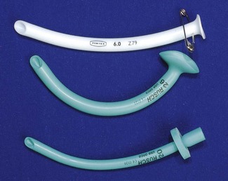
Nasopharyngeal airway
The nasopharyngeal airway is designed to be passed through the nares and along the floor of the nose to deliver the tip beyond the soft palate to lie in the oropharynx, above the epiglottis. It can bypass nasal, soft palate and tongue base obstruction. The tubes have either a fixed or adjustable flange (Fig. 6.6) at the proximal end to prevent loss of the device into the nose and to limit insertion of an excessive length. The tip is bevelled to make its passage through the nose less traumatic. Some designs have a hole cut in the wall opposite the bevel to maintain patency if the tip becomes obstructed. They are produced in a range of sizes with the length of the airway governed by the internal diameter of the tube.
Nasopharyngeal airways are often indicated where a patient has limited jaw opening, awkward or fragile dentition or where an oropharyngeal airway is frequently displaced by a marked overbite. They are well tolerated by patients during relatively light levels of anaesthesia and during emergence. To avoid traumatic insertion and heavy bleeding nasopharyngeal airways are ideally soft (plastic, polyurethane or latex rubber). Avoiding excessively large tubes also minimizes complications during use, but the tube must be long enough to extend well into the oropharynx. An estimate of appropriate length is the distance from the tip of the nose to the tragus of the ear.
Facemasks
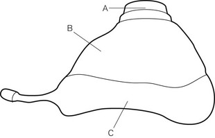
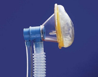
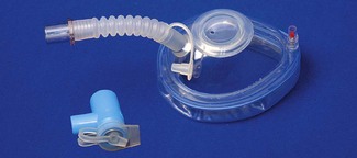
Anaesthetic facemasks are designed to fit over the patient’s nose and mouth and enable the creation of a low pressure seal. This should not require excessive force. The facemask (Fig. 6.7) consists of three parts: the mount, the body and the edge. A snug fit is achieved by incorporating one or more of the following features into the design: by anatomically shaping the body, by the use of an air-filled cuff at the edge (Figs 6.8B, D and E) that has a soft cushioning effect or by a soft pliable flap (Figs 6.8A and C) that takes up the contour of the face.
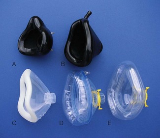
The body may be made from black rubber, neoprene, plastic, polycarbonate or silicone rubber. In some cases, a malleable wire stiffener or wire gauze is incorporated in the body so that the shape may be altered to fit the patient’s face. The transparent body of a polycarbonate or plastic facemask permits continuous inspection of the airway and respiration to be monitored by the appearance of condensation during exhalation. This is useful during anaesthesia and particularly during resuscitation. A transparent facemask also affords the possibility of seeing regurgitant matter or vomitus emerging from the mouth. Such masks are perhaps less threatening to children and anxious adults (Figs 6.8C, D and E).
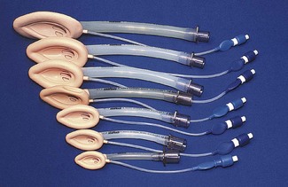
The internal volume (apparatus dead space) within the body of the facemask is relatively unimportant in adults but may assume significance in neonates and infants where it can constitute 30% or more of their tidal volume. Several designs shape the paediatric facemask to minimize the apparatus dead space (Fig. 6.9). In spite of this, good fit may be more important than theoretical apparatus dead space: paradoxically in paediatrics, a larger facemask particularly of the Rendell-Baker or Laerdal type, may allow the face to fit further into the mask with improved fit and reduced effective apparatus dead space.
The edge may be anatomically shaped and fitted with a cuff or flap. A good fit is essential to prevent dilution of administered gasses by room air during spontaneous respiration and to allow positive pressure ventilation without gas leak. A variety of types and sizes of facemask must be available, since none will be a good fit for every face. Edentulous or bearded patients may be especially difficult. The former are best managed by leaving any dentures in place to prevent the cheeks from falling away from the mask and by using a smaller mask. Beards often prevent a good seal around the edge of the mask and a leak-free fit may sometimes be achieved with a bigger mask held firmly with two hands. Anaesthetists have often had to go to bizarre lengths to achieve a useful seal in heavily bearded patients (e.g. using a pierced defibrillator gel pad on the face3 or even wrapping the entire head in clingfilm4). Reusable masks with a cuff have a small filling tube fitted with a plug to enable the degree of inflation to be regulated. The plug must be removed to allow the cuff to deflate if the mask is to be autoclaved.
The shift towards disposable single-use facemasks avoids the cost of sterilization (increasingly performed off-site for many hospitals) packaging, and mandatory tracking and trace systems, but risks a reduction in quality. The same principles of design nevertheless apply to plastic disposable facemasks (Figs 6.8C, D and E). Materials and components are cheaper and of lower quality, but more importantly there is a much more limited range of designs and sizes. Most, even those for paediatric use, are essentially based on the one design of air-filled cuff and cone-shaped body. As they are reproduced with differing quality and materials by numerous manufacturers, uniformity of performance cannot be assumed. They may be advertised with bold claims of high performance and popularity but formal clinical evaluation is not a pre-requisite to bringing them to market. Several new designs have been found to be substandard and it is wise to assess performance before changing devices. Sizes do not necessarily equate between manufacturers. Some single-use masks do not allow adjustment of the volume of the air-filled cuffs and these may be both under filled and of less pliable plastic leading to a poor-quality seal. Poor design or poor fit, even in the absence of a leak, can cause areas of high pressure on the skin, which if unchecked, could lead to ulceration. Single-use masks do, however, have a number of advantages beyond sterility. These include use of inert plastics (eliminating risk of allergy to latex), transparency and even the potential to add scent to the plastic making the products more readily accepted by patients.
Many anaesthesia masks are supplied with a ring device that has several lugs protruding to allow attachment of a head harness. Older black rubber masks have a similar metal harness ring (Figs 6.8A, D and E). A head harness may be used to allow facemask anaesthesia while allowing the anaesthetist to keep both hands free. Since the introduction of supraglottic airways head harnesses are rarely used, if ever, except during non-invasive ventilation (see below).
Masks for some dental anaesthetic techniques are designed to fit the nose only, so that the dentist has unimpeded access to the mouth (Fig. 6.10). They are also known as nasal inhalers.
Facemasks are also used for non-invasive ventilation (NIV) or continuous positive airway pressure (CPAP) in differing scenarios, both in and out of hospital (see Chapter 7, Fig. 7.17). These are similar to anaesthesia facemasks and may cover the mouth and nose (conventional CPAP) or just the nose (for nasal CPAP). Such masks tend to be single-patient use devices made of plastics and soft silicone rubber. They are usually of a higher quality than single-use anaesthesia masks as comfort and tolerability is the key to treatment compliance and success. CPAP masks often incorporate additional ports for valves and airway manometry and have attachments for a retention harness to keep the mask comfortably on the patient’s face.
Supraglottic airways
History
Prior to 1988 maintaining a clear airway in a non-intubated, anaesthetized patient, might well have involved elevating and protruding the lower jaw, supporting it in this position with a Guedel airway, placing a facemask over the nose and mouth and securing this with a Clausen’s (head) harness to provide a gas-tight fit: all essentially dextrous tasks requiring practised performance. Although preceded by numerous devices that were designed to control the airway without tracheal intubation, it was not until the advent of the Laryngeal Mask Airway (LMA), first described in 1983,5 and introduced commercially in 1988, that such devices achieved success in anaesthesia. It soon became evident that the LMA allowed all the tasks described above to be replaced with a single device requiring minimal training in its use, but with an astonishing success rate in achieving a clear leak-free airway. Within a year of its introduction all UK hospitals had placed orders: the anaesthetic ‘supraglottic revolution’ had begun.
Since that time more than 40 novel, and less novel, supraglottic airway devices (SADs) have been brought to market. Since 2003 numerous manufacturers have produced copies (or near copies) of the LMA, most of them disposable and plastic. Many new supraglottic devices are based on the general design of the LMA and several are based on the Combitube (see below), which, although in origin pre-dates the LMA,6,7 was (and remains) more a device for airway rescue than for routine anaesthetic use. Other novel approaches to SAD design have met with varying degrees of success. No design has so far proven as popular as the LMA, in spite of the occasional publications claiming similar or better performance.8,9
Features
SADs generally have the following features in common:
• An inflatable cuff that sits over or above the level of the larynx. A minority of devices are cuff-less. Crucially, in all SADs, function relies on an open laryngeal inlet.
• ‘Blind’ insertion is possible, obviating the need for laryngeal visualization.
• They rely, for correct positioning, on a soft distal tip that lodges in or just above the upper oesophagus behind the cricoid ring. A minority sit well above this.
• There is an inability to guarantee tracheal isolation from gastric contents in the event of reflux or vomiting. This issue is increasingly being solved.
• The use of wide bore tubing for the airway tube (as this is not limited by the size of the larynx and trachea), and which can therefore be used as a conduit for other instruments such as a tracheal tube or a flexible endoscope.
• An ISO 15 mm male connector proximally enables connection to an angle piece, catheter mount or breathing system.
Terminology
The term originally coined to describe the generic group of LMAs and other similar devices is supraglottic airway devices (SADs). The term extraglottic has been suggested as more accurate by some authors.10 The term SAD has the advantage of primacy and widespread use and is adopted here. Several authors have attempted to classify SADs on the basis of patient or device anatomy but the classifications are cumbersome and not widely adopted.11 The author of the previous incarnation of this chapter attempted (to no avail!) to introduce the term ‘augmented supraglottic airway’ to delineate simple oral and nasopharyngeal airways from those supraglottic devices that aim to provide a gas-tight seal to the airway.
This author has coined the phrase first-generation and second-generation SADs to demarcate those devices which are simple airway tubes (first generation), from those which are designed with the intention of reducing the risk of pulmonary aspiration of gastric contents (second generation). The proposed advantage of this classification is that it is simple, is not dependant on patient/device anatomy, but is ‘patient centred’. Second-generation devices may be designed to improve patient safety, but the effectiveness of this design feature is not proven in all cases. Second-generation devices comprise the ProSeal LMA, the Combitube and Easytube, the Laryngeal Tube Suction mark II, the Streamlined Liner of the Pharynx Airway, the i-gel and the Supreme LMA.
Pharyngeal seal and efficacy vs oesophageal seal and safety
Several recent studies indicate that the extent of oesophageal seal varies considerably between different SADs.12–15 They also demonstrate that under experimental conditions in cadavers, those with a drain tube will usually effectively vent regurgitant fluid provided the drain tube is not occluded. Particulate matter has not been studied. These are important findings, though their clinical correlates are not in all cases confirmed.
First-generation SADs
The laryngeal mask airways
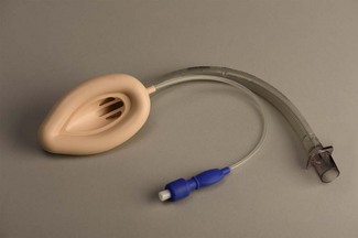
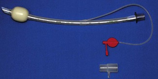
The LMA Classic
The mask (distal) end of the cLMA is made of medical grade silicone and consists of a shallow bowl resembling a small facemask, which is surrounded by an inflatable tubular cuff (Fig. 6.11). The latter, when inflated, fits around the laryngeal inlet and supports it in a position away from the posterior pharyngeal wall. The back of the bowl leads into a semi-flexible tube which passes out of the pharynx and mouth and has a 15 mm ISO male connector so that it can be attached to a breathing system. At the point the tube enters the mask, there are two thick silicone rubber strands (grilles, or bars) designed to prevent the epiglottis falling into it and occluding the lumen. The mask cuff is inflated via a pilot tube that terminates in a small ‘pilot balloon’ giving an indication of cuff inflation/deflation. A self-sealing valve prevents deflation of the cuff.
cLMAs are made from silicone rubber so that they can be autoclaved and reused. The manufacturer has designated the cLMA for 40 uses. Experience suggests the cLMA can withstand many more cycles of sterilization, but this is ‘off label’ use and cannot be recommended. Originally produced in four sizes, two mid-range sizes and two further larger sizes were added later (Fig. 6.11).
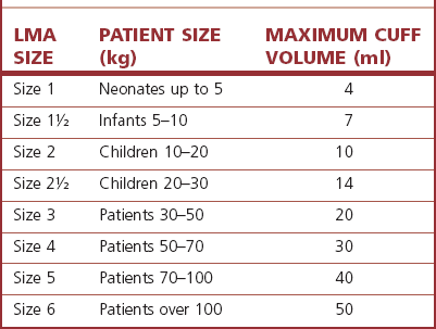
Experience with sizes 1 and 6 is comparatively limited. It should be noted that, although originally developed from plaster casts of cadaveric adult larynxes, subsequent sizes are simply scaled versions of the originals. As infant and paediatric laryngeal anatomy varies considerably, the smallest sizes may not provide as reliable an airway as adult sizes. The manufacturer’s recommendations are as shown in Table 6.1. Where the predicted size does not fit well, an alternative size may provide a better airway.
The term LMA is a registered trademark of Intavent Ltd, UK.
cLMA dimensions relevant for its use as a conduit
The size of tracheal tube that can be passed through a given size of cLMA varies as tracheal tubes of the same internal diameter can have different external diameters depending on the model and manufacturer (Table 6.2).
Table 6.2 Size of tracheal tubes that can be passed through a cLMA. The tabulated results are for a lubricated Portex blue line uncuffed tracheal tube* passed without force in a cLMA. If using a cuffed tracheal tube, reduce the size of tube by 0.5 mm. The results do not apply to laryngeal masks other than the LMA Classic. Distances are to the mask grilles: intubation would require longer tracheal tubes. (*External diameter ranges from 1.3 to 2.6 mm greater than internal diameter (ID), increasing as internal diameter rises.)
| cLMA SIZE | SIZE OF UNCUFFED TT PASSABLE (mm ID) | DISTANCE FROM CONNECTOR TO MASK GRILLES (mm) |
|---|---|---|
| 1 | 3.5 | 108 |
| 1½ | 4.5 | 135 |
| 2 | 5.0 | 140 |
| 2½ | 6.0 | 170 |
| 3 | 6.5 | 200 |
| 4 | 6.5 | 205 |
| 5 | 7.0 | 230 |
Inserting the LMA
Standard insertion
General anaesthesia should be adequate to allow generous mouth opening and jaw thrust without response. Under such circumstances there should be no need to use neuromuscular blockers. The patient’s head and neck are then placed in the ‘sniffing position’. The manufacturer’s recommended insertion technique requires that the cuff is deflated as above and the LMA is grasped like a pen in the dominant hand. The tip of the operator’s gloved index finger is placed at the junction of the tube and mask whilst the non-dominant hand maintains the position of the head and neck by cradling the occiput so that the patient’s mouth falls open. The mask is inserted into the mouth and the bowl is kept pressed against the hard palate as it is advanced in one smooth movement into the hypopharynx. The upward pressure against the palate flattens the cuff of the mask to give a smooth thin leading edge. The hard and then the soft palate and finally posterior pharyngeal wall act as a scoop to guide the mask into place and prevent snagging on the tongue or epiglottis. The mask is advanced until resistance is felt. For many people the index finger is not long enough to fully insert the LMA: the hand in the mouth, guiding the LMA, should remain in place while the hand on the occiput can now be used to push the LMA stem inwards (still guided by the hand in the mouth) until resistance is felt. The LMA is not fully inserted until it reaches resistance, signifying reaching the cricopharyngeal constrictor. Without holding the tube the cuff is then inflated with air. The manufacturer indicates a maximum volume for cuff inflation which must not be exceeded; inflation to an optimal pressure is preferable (see below). Use of the maximum volumes is likely to lead to excessively high intracuff pressures that reduce the device’s efficacy and safety profile. Where inflation to a predetermined volume is used, half the manufacturer’s recommended maximum is a good starting point.
Confirmation of correct placement
Remarkably, for a device that is inserted blindly, the mask almost always adopts the correct position and provides a patent airway with a success rate above 95%.16
Indications for using the LMA:
Instead of a facemask and pharyngeal airway, with the added benefit of:
1. releasing the anaesthetist’s hands to deal with other matters, and removing them from proximity to the operative site
2. providing a more reliable airway, particularly in patients placed in positions other than supine or where a facemask does not seal well against the face as in bearded patients.
Instead of a tracheal tube, in certain circumstances, for example:
1. elective procedures involving spontaneous or controlled ventilation, where tracheal intubation would have been used only to enable a ‘hands-free’ and gas-tight airway
2. elective procedures where intubation and the necessary drugs may elicit particularly undesirable cardiovascular or respiratory responses
3. patients in whom difficult intubation (but not difficult airway or mask ventilation) is predicted, as in those with cervical spine problems or moderately limited mouth opening, usually as a prelude to intubation via the LMA
4. as a first choice airway for use in emergencies by non-anaesthetic staff on the basis that success rate at establishing ventilation for non-specialist staff is greater with the LMA than with facemask ventilation or tracheal intubation.8
1. The LMA can be used as an aid to extubation and recovery, even after peroperative tracheal intubation. The LMA is less stimulating than a tracheal tube and less likely to elicit coughing and straining during recovery. It also protects the larynx from blood and secretions arising from the nasopharynx and oropharynx. An example of such use would be insertion of the LMA at the end of a tonsillectomy to facilitate a smooth wake-up. Placement of the LMA is much easier if the tracheal tube is at first left in place to guide insertion of the LMA. The device is advanced over the posterior aspect of the tracheal tube which ensures that the tongue and epiglottis are easily negotiated and the larynx may be held forward allowing the tip of the LMA to seat more easily behind the cricoid. The tracheal tube can then be removed.
For difficult airway management:
1. To provide a conduit to facilitate intubation. The LMA orifice lies directly over the laryngeal inlet in >90% of cases. In theory a gum elastic bougie or narrow long tracheal tube may be passed blindly through the LMA to enter the trachea; however, in practice, success rates are as low as 10–25% and such a ‘blind technique’ also risks trauma to a potentially already compromised airway. Far preferable are flexible endoscopic guided techniques, with use of an Aintree catheter being the best technique (described below).
2. To rescue the airway when intubation and/or facemask ventilation have failed. There is now considerable evidence to support the use of the LMA in these scenarios, some even suggesting that the LMA is more likely to be an effective airway in those in whom intubation has failed than it is in the general population. The device is consequently recommended in all international airway management algorithms.
1. There is considerable interest in use of SADs for maintenance of the airway during cardiopulmonary resuscitation. Several SADs are now recommended by the resuscitation councils. The largest bulk of evidence supports the use of the LMA, though several newer SADs that enable a higher pharyngeal seal may offer additional protection against regurgitation/aspiration and have potential benefits. The LMA may be used as a primary airway by those with little or no intubation skills and as a rescue device when tracheal intubation fails or is impractical because of patient entrapment. It may be easier for non-anaesthetists to achieve ventilation with a SAD than with a facemask.17
Contraindications
Accepted wisdom has it that the LMA does not protect the lungs against aspiration of refluxed or regurgitated gastric contents. In reality it offers some protection in the unconscious patient and therefore is ‘safer’ in this respect than facemask ventilation, with or without simple airway adjuncts.13,15 However, the LMA does provide less protection than the tracheal tube. The LMA should, therefore, not be used in patients with a full stomach or risk factors for regurgitation/aspiration (delayed gastric emptying, hiatus hernia, etc.).
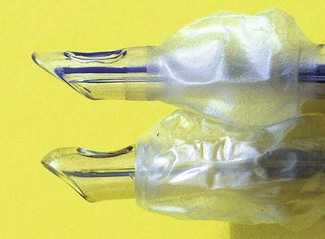
LMA Flexible
The reinforced (or flexible) LMA (Intavent Direct, Maidenhead, UK) is an alternative version of the LMA in which the tube is thinner, narrower and longer and is reinforced with a spiral of steel wire to add flexibility and reduce the risk of kinking; it is available in sizes 2–5 (Fig. 6.12). Placement of the flexible LMA (fLMA) requires meticulous technique to prevent rotation leading to mask misplacement: the mask can rotate 180o about the axis of the airway tube, leaving the mask orifice facing backwards, without this being evident proximally. In performance terms the main difference between the fLMA and the classic LMA is that, once placed, its proximal tube can be moved in any direction without those movements being transmitted to the mask end of the device and leading to displacement. This makes the fLMA very popular for head and neck and intraoral procedures and enables the tube and breathing circuit to be positioned away from the operative site. Because the mask portion of the fLMA isolates the lower airway from above it is suitable for nasal and dental procedures. It may be used without a throat pack (therefore bypassing the risk of throat pack retention) though careful attention is required of both surgeon and anaesthetist to ensure surgical debris is not in the oral cavity during emergence. The fLMA is routinely used by a minority of anaesthetists for tonsillectomy where it can reduce the risk of blood entering the trachea during recovery from anaesthesia.
Other ‘laryngeal masks’
Cuff pressure monitoring
One novel design feature is an integrated cuff pressure monitor, currently unique to one manufacturer. The ‘Cuff Pilot’ (Ultimate Medical, Victoria, Australia) is a simple pressure indicating device incorporated into the inflation valve to give a constant visual representation of intracuff pressure (Fig. 6.13).
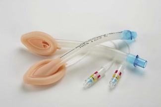
Figure 6.13 A single-use laryngeal mask incorporating Cuff Pilot cuff pressure monitoring device.
Photograph courtesy of Ultimate Medical Pty, Victoria, Australia.
One other manufacturer (Armstrong Medical, Coleraine, UK) produces a pilot balloon that simply and visibly herniates above recommended pressures (Fig. 6.14).
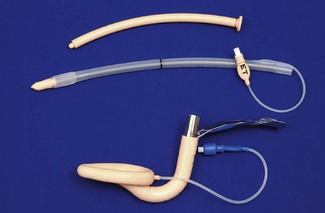
Intubating LMA
The intubating LMA (ILMA, Intavent Direct, Maidenhead, UK) was designed specifically to enable (blind) tracheal intubation by capitalizing and improving on the LMA’s high success rate at guiding instruments within its lumen into the larynx (Fig. 6.15).18,19 It is significantly different from the classic LMA: the bowl of the device is rigid as is the short, wide right-angled (approximately 110°) airway tube, which is constructed of stainless steel. This necessitates a novel insertion technique and a handle is provided to allow manipulation of the position of the bowl. Instead of grills across the mask orifice there is a semi-rigid flap designed to lift the epiglottis as the tracheal tube enters the bowl of the mask and prevent impaction of the tracheal tube. The device is supplied with a dedicated tracheal tube made with a soft rounded silicone ‘bullet-shaped’ tip to better negotiate the curve of the device and which is less traumatic when impacting the larynx. The ILMA tracheal tubes range in size from 6.0 to 8.0 mm ID, with all size tubes passing through all ILMAs.
Intubation through the ILMA involves four steps:
2. reattachment of the breathing circuit and manual ventilation to determine the optimal position (highest compliance, lowest resistance). ILMA position is adjusted as necessary
3. while maintaining the ILMA in the optimal position the ILMA tracheal tube is advanced into the trachea and correct placement confirmed
4. removal of the ILMA over the tracheal tube and reattachment of the tracheal tube to the breathing circuit.
Although the ILMA lies over the glottis rather less frequently than other LMAs, successful blind intubation is enhanced by features that ensure the tracheal tube exits the mask at the correct angle and in the midline. With good technique first time success rate of 75% is achieved; increasing to 88–95% with two or more attempts.20,21
Particularly with the increased availability of flexible endoscopes, the exact role for the ILMA is questionable, given that it cannot be relied upon as a blind technique in the difficult intubation scenario and that for use as a conduit for a flexible endoscope the view may be better through an ordinary LMA.22,23 Experience with the device as an airway is limited and it cannot be recommended for routine use;24 this, together with the different insertion technique compared to the classic LMA, compounds problems associated with its use.
Other first-generation SADs
Even excluding single-use versions of devices there are currently more than 10 different varieties of supraglottic airway available in the UK. Several others have been withdrawn from the market but it is likely that even more are under development. This situation reflects the considerable success of the cLMA and other SADs. Not all currently available SADs have clearly demarcated applications and a full analysis of their merits and demerits is beyond the remit of this chapter. Many of the issues touched upon in the section on the LMA are equally pertinent to these other products. The most important of these devices are briefly discussed here.
Laryngeal tube
The Laryngeal Tube (LT) (VBM Medizintechnik GmbH, Salz, Germany) was first made in 1999 and consists of a slim airway tube with a small balloon cuff attached at the tip (distal cuff) and a larger asymmetric balloon cuff at the middle part of the tube (proximal cuff). Both cuffs are inflated through a single pilot tube. After insertion it lies along the length of the tongue with proximal and distal cuffs lying in the oropharynx and oesophageal inlet, respectively (Fig. 6.16). Inflation creates a seal and ventilation occurs through orifices between the cuffs. The device is made of silicone and is reusable up to 50 times. Seven sizes are available for all patient ages and sizes, with colour-coded connectors. Size selection for sizes 0–2 is based on patient weight and for sizes 2.5–5 on height. For adults a size 3 is suitable for patients below 155 cm height, size 4 for patients between 155 cm and 180 cm tall, and a size 5 in patients 181 cm or taller. Adult sizes are supplied with a reusable silicone bite-block.
The literature on the LT is somewhat confused by the multiplicity of versions that have been evaluated.25 The slim profile of the LT allows easy insertion with little mouth opening and with the redesigned softer distal tip the device causes minimal airway trauma. Initial evaluations, with the original device, reported variable success rates: in particular spontaneous ventilation success was poor. More recent studies suggest high success rates for insertion (above 95%) and good airway seal pressure (approx. 26 cm H2O).9 It has a steep learning curve and may be suitable for use by non-anaesthetists and out of hospital.
The main limitation of the LT is that its tube-like shape provides little protection against axial rotation and this, combined with small ventilation orifices, tends to lead to a significant incidence of partial or complete airway obstruction. Compared to LMAs the LT is more likely to lead to airway obstruction, and less likely to lie over the larynx.26
CobraPLA
The Cobra Perilaryngeal airway (CobraPLA) (Engineered Medical Systems, Indianapolis, USA) is a relatively new single-use SAD (Fig. 6.17). The distal end (whose shape lends the name to the device) consists of a soft plastic head designed to seat in and seal the hypopharynx, with the anterior surface lying at the laryngeal inlet. The anterior surface of the head consists of a grille of bars soft enough to allow instrumentation of the larynx, but their presence prevents epiglottic obstruction of the device orifice. A proximal inflatable balloon is designed to elevate the tongue base and seal the oropharynx.
The CobraPLA is supplied in eight sizes designed for use in patients ranging from neonate (size 1) to >140 kg (size 6). The internal diameter of the CobraPLA airway is larger than the corresponding cLMA: for the largest CobraPLA this is 12.5 mm.
The CobraPLA is designed for spontaneous and controlled ventilation and was modified in 2006. There is limited published experience and none with the largest and smallest sizes. Available evidence indicates 80% first attempt insertion success, airway seal of approximately 25 cm H2O and minor morbidity of similar frequency LMAs.27,28 A significant number of cases may require airway manipulation (pull/push) to maintain the airway.
As the CobraPLA is designed to be inserted to full depth and then withdrawn 0.5–1 cm, the tip likely does not obturate the oesophagus, which may be of significance in positive pressure ventilation: raised pharyngeal pressure being fully transmitted against the upper oesophageal sphincter. The pharyngeal cuff may prevent egress of regurgitant matter from the oropharynx, and hence increase the risk of aspiration.29,30 With the exception of a modest increase in airway seal, there do not appear to be any benefits for use over the cLMA.
Second-generation SADs
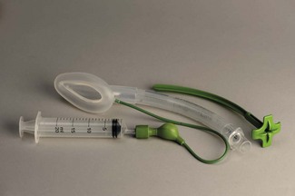
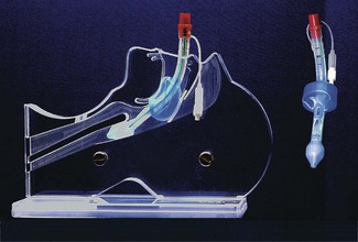
LMA ProSeal
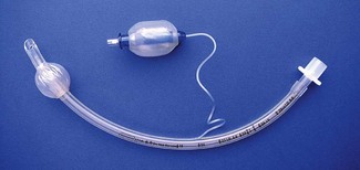
The LMA Pro-Seal (Intavent Direct, Maidenhead, UK) (PLMA), which was introduced in 2000, is an important addition to the family of LMAs.31 It was designed with three refinements in mind: (1) improved performance during controlled ventilation, (2) improved safety regarding aspiration, and (3) an ability to diagnose misplacement of the device tip.
The PLMA has a softer, larger and deeper mask bowl than the cLMA (Fig. 6.18). The mask cuff extends over the posterior aspect of the bowl pushing it forward when inflated. A drainage tube passes from the tip of the mask, through the bowl, to run parallel to the airway tube. Proximally these are joined by an integral bite block. The changes to mask shape, size and the posterior cuff increase the median airway seal by >80% to above 30 cm H2O.32 A full range of sizes is available with paediatric ones lacking the posterior mask cuff.33
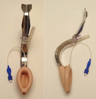
The PLMA may be inserted digitally (like the cLMA), or by attaching a metal introducer (Fig. 6.14) or by railroading the whole device via its drain tube over a bougie placed in the oesophagus.34 The latter technique is the most successful and least likely to lead to misplacement.35 It is the technique of choice when first-time insertion success is critical, such as when managing a difficult airway. A gastric tube can be passed through the drain tube when indicated: this should be well lubricated and not refrigerated. The drainage tube allows such reliable insertion of an orogastric tube that inability to do so indicates the PLMA is misplaced with the posterior of the mask folded backwards. Although maximum volumes for cuff inflation are published by the manufacturers, inflation to an intracuff pressure of 60–70 cm H2O is preferable.
A series of post-insertion tests are designed to confirm correct device positioning.32 First a small amount of gel occluding the proximal drain tube should not be displaced when a pressure of 20 cm H2O is applied to the airway; this tests separation of the gastrointestinal and respiratory tracts and fails when the PLMA is not pushed in far enough, allowing gas to pass directly from the airway tube up the drain tube. Second, no more than one-third of the bite block should be visible as this also suggests incomplete insertion. Third, pressing on the chest should not displace the drain tube gel; if it does it suggests the drain tube tip has entered the glottis, though airway obstruction is likely to coexist. Finally, pressure at the suprasternal notch should lead to the drain tube gel bulging outwards; this tests that the drain tube is not folded over as suprasternal notch pressure is transmitted to the oesophagus and then to the drain tube, unless the tip is folded over. If doubt exists, attempting to pass a gastric tube (approximately 30 cm in adults) to the tip of the drain tube, or beyond will identify whether it is folded over. In practice these several tests can be carried out in a matter of seconds to confirm correct positioning and function of the PLMA with further attention only necessary if a test is not ‘passed’.
Compared to other LMAs and LMs the PLMA creates a higher seal with pharynx and oesophagus. It enables more reliable controlled ventilation and increases the patients and indications where a supraglottic airway is appropriate. The PLMA also exerts less pressure against the mucosa than either cLMA or ILMA, so reducing the potential for mucosal trauma and damage. These advantages must be balanced against slightly greater difficulty in insertion of the PLMA. When combining a large number of studies, first-time insertion success with the PLMA is 85% and with the cLMA is 93%.32,36 In contrast a bougie-guided technique is almost 100% successful. The PLMA has potential roles in difficult airway management and is perhaps the logical choice for rescuing the airway after failed rapid sequence induction.35,37
There is good theoretical and performance evidence to support the view that compared to the cLMA the PLMA does reduce gastric inflation and increases protection from regurgitated gastric contents. However, this is entirely dependent on correct positioning of the device. The PLMA lies with the drain tube in continuity with the oesophagus and the airway tube in continuity with the trachea. As the pharyngeal and oesophageal seals are both increased this creates functional separation of the gastrointestinal and respiratory tracts. The drain tube vents gas leaking from the mask towards the oesophagus and prevents gastric distension. It also vents regurgitated stomach contents. Design and performance features of the PLMA make it likely that its use reduces the risk of gastric inflation and protects from aspiration if regurgitation occurs. Extensive evidence from bench work, cadaver and clinical studies strongly support this claim, but it is unproven and probably unprovable in clinical use. Cadaver studies show an oesophageal seal of 70–80 cm H2O and efficacy of the drain tube in venting regurgitated fluid.14 There are several case reports of regurgitated matter being vented by the drain tube.
There are several studies comparing PLMA performance with other SADs. In all of these to date the PLMA performs as well as or better than alternative devices. Infrequent complications associated with the PLMA include oesophageal breathing, gastric insufflation and airway obstruction.32
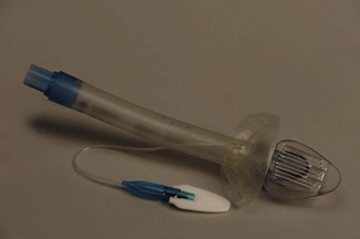
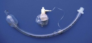
LMA Supreme
The LMA Supreme (Intavent Direct, Maidenhead, UK), the newest of the LMAs introduced in 2009, is a single-use SAD (Fig. 6.19) made of PVC and designed to combine the most useful elements of the PLMA (improved seal, drain tube, integral bite block) with the ease of insertion of the ILMA in a single-use device. The manufacturer’s indications for use are the same as the PLMA. Despite this, it is not simply a ‘a single-use’ version of the PLMA as there are several important differences: the stem and mask are more rigid as is the bite block; the drain tube runs within the airway and divides it into two narrow channels and the bowl of the mask includes patented ‘fins’ that are designed to prevent airway occlusion by the epiglottis.
Due to its newness the SLMA has been less completely clinically evaluated than other LMAs.38 It is very easily and reliably inserted, even by novices.17 Once inserted ventilation is reliable and the pharyngeal seal (approximately 24–28 cm H2O) is higher than the cLMA but lower than the PLMA. The airway sits over the larynx as frequently as the cLMA or PLMA. An orogastric tube can usually be passed via the drain tube. In a direct comparison between the SLMA and i-gel (see later), performance of the two devices during simulated airway rescue was equivalent.39 While efficacy in low-risk patients is therefore largely established, its further performance is not. The effectiveness of the drain tube is yet to be reported. Further evaluation is awaited before it can be recommended for the same extensive a range of indications as the PLMA but early impressions suggest the SLMA will have indications both in and out of hospitals for a wide range of indications.
i-gel
The i-gel (Intersurgical, Wokingham, UK) is a novel single-use, cuffless SAD made of a medical-grade elastomer gel (styrene ethylene butadiene styrene). Its shape partially resembles the inflated PLMA. It has a short wide-bore airway tube with no grilles, an elliptical shaped stem, an ‘anatomically’ shaped bowl, an integral bite block and a drain tube (Fig. 6.20). These features provide low resistance to gas flow, stability, improved pharyngeal seal, the potential for good access to the airway as a conduit, and possibly decreased risks of airway occlusion or aspiration.
The i-gel is very easily inserted, by experienced and novice users, due to both low frictional properties and the lack of a cuff needing inflation.40,41 The pharyngeal seal is 24–28 cm H2O in most cases, but in a minority is considerably lower and ventilation is not possible. An alternative size should be tried before abandoning the device. Several authors describe that the elastomer’s ‘thermoplastic’ properties leading to an improving seal over time as the device warms, but this is an inconsistent finding and it is also seen with cuffed devices. It is just as likely due to a combination of adaption of the pharynx to the shape of the device within it, and better relaxation with deeper anaesthesia.
Although the drain tube is smaller gastric access is as reliable as for the PLMA, but the i-gel has lower pharyngeal (ventilation) and oesophageal (protection from regurgitation) seal pressures than the PLMA.14,38 Whether this has any clinical importance in practice is not yet clear. The same studies report the drain tube is effective in venting regurgitant fluid, unless it is blocked.14,42 The i-gel was intentionally designed with a truncated tip to reduce compression of the oesophageal sphincter and so reduce dysphagia, which may account for the reduced oesophageal seal. On the available evidence it would seem prudent to remove any orogastric tube after use as the i-gel oesophageal seal may not protect the airway if the drain were to become blocked. Cases of protection from aspiration with the i-gel are reported, as is one case of partial aspiration.43
Combitube
The Combitube (Covidien, Ireland) originally marketed as the Oesophageal Tracheal Combitube (Fig. 6.21) is a development of the oesophageal obturator airway. It is a single-use device and is conceptually different from other SADs in that it is designed to provide an airway after blind placement in either the trachea or the oesophagus. It has two cuffs (like the Laryngeal Tube) and two tubes. The lumen of one tube opens beyond the distal cuff, whilst the other ends between the two cuffs and has only side openings. There were originally two sizes, 37 Fr and 41 Fr, for small and larger adults. A smaller size 26 Fr was recently introduced along with other modifications aimed at reducing the incidence of trauma.
With the head and neck flexed or in the neutral position it is inserted blindly into the mouth and advanced until the teeth reach between the depth marks. First the proximal high-volume pharyngeal cuff is inflated with 90–100 ml of air to fix the device in place then the lower cuff is inflated with about 15 ml. When inserted blindly, the Combitube almost invariably enters the oesophagus. The proximally longer tube, marked ‘1’, has the lumen ending between the cuffs and ventilation is first attempted through this lumen. If this fails then the second lumen is tried. If oesophageal insertion is confirmed, tube ‘2’ can be used to insert a gastric drain with the smaller balloon acting as an oesophageal obturator. An oesophageal detector device, such as Wee’s device, can be used to confirm the position of the tube tip before ventilation, thereby preventing inflation of the stomach in those cases where the device enters the trachea. Where ventilation with the Combitube fails, this may be due to obstruction of the larynx by the oropharyngeal balloon; the device should be withdrawn by 1–2 cm and ventilation attempted again.25 The incidence of trauma with the Combitube is higher than other SADs and oesophageal rupture must be considered an inherent risk;44,45 the mechanism may involve raised oesophageal intraluminal pressure as a result of obturation, as well as direct injury by the device.
Due to its cost, trauma associated with insertion and the potential confusion of the dual tubes, the Combitube has been superseded by other SADs and has no role in routine elective anaesthesia. It is targeted primarily now at emergency airway management and non-anaesthetic use. The Combitube may have a role in out-of-hospital airway rescue in those trained in its use. It is part of the ASA difficult airway management algorithm and ILCOR recommendations for airway control during cardiopulmonary resuscitation.46
The Laryngeal Tube Suction mark II
In 2002 the Laryngeal Tube – Suction (LTS) (VBM Medizintechnik, Salz, Germany) was introduced as a modification of the Laryngeal Tube, with a drain tube lying posterior to the airway tube to enable gastric tube placement and prevent gastric inflation during ventilation. While the design aimed to increase device safety (compare cLMA and PLMA) the new device was much more bulky, harder to introduce, and potentially traumatic: thereby losing two of the LT’s principal advantages.47 In 2005 the mark II LTS (LTS II) was introduced with a slim profile tip and an asymmetric oesophageal balloon. Size selection, insertion technique and reusability for the LTS-II are identical to the LT.
The LTS-II offers the potential for expansion of the role of the LT. It is easier to insert than the LTS and its pharyngeal seal is similar to the PLMA. Evidence of ease of insertion and incidence of airway obstruction remains inconsistent, but is generally improved.48
Like the LT, in cadavers, the LTS-II seals well with the oesophagus to a pressure of 70–80 cm H2O and the drain tube effectively vents regurgitant fluid.15
Considerably more evidence is needed before the LTS-II role is fully established.
A single-use version of the LTS-II exists (confusingly) called the LTS-D.
SLIPA
The Streamlined Liner of the Pharynx Airway (SLIPA) (SLIPA Medical, Isle of Man, UK) is an inexpensive single-use SAD of novel design, a blow-moulded airway made of a polyethylene based composite with the shape mimicking a ‘pressurized pharynx’ (Fig. 6.22). It was first launched around 2003, although issues with choice of manufacturer and distributor continue to affect availability in the UK and independent evaluations of the device are so far scarce. The SLIPA slightly resembles a boot. It has no cuff, is hollow and is designed to sit with the toe of the boot in the hypopharynx. Lateral prominences in the mid-portion of the airway are designed to locate in the pyriform fossae and the mask displaces the tongue base anteriorly, with the intention of producing a stable device with an improved airway seal.
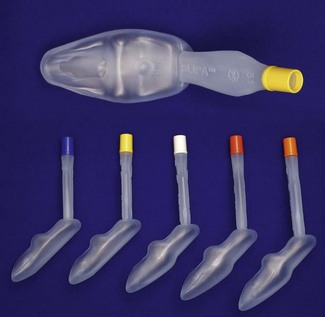
Figure 6.22 SLIPA (SLIPA Medical, Isle of Man, UK) disposable supraglottic airway device in a range of adult sizes.
The SLIPA is included in the second-generation SADs on the basis of design only. The inventor reports that the interior of the SLIPA provides a protective reservoir able to accommodate 50–70 ml of fluid (compared to a 5 ml capacity of the cLMA).49 There are no clinical data to support the clinical relevance of this claim.
Early cohort and comparative trials by the inventor showed satisfactory insertion performance.50 A few small independent trials have been performed which are supportive of its use showing adequate insertion success and pharyngeal seal pressures similar to the LMA.51,52 Trauma and bleeding are potential concerns.
Sads summary
The topic of SADs is complex with too many devices and variants of each. The LMA Classic is a highly reliable and safe device and remains the SAD against which all others should be benchmarked.53 For many newer SADs there is too little research to perform benchmarking and where appropriate evaluations have been performed several first-generation SADs (airway tubes) appear to offer little, if any, benefit over the classic LMA.
Tracheal tubes
A cuffed tracheal tube, once placed, provides the greatest likelihood of protection for the lungs from inhalation of foreign material, the tube is the least likely device to be dislodged, glottic reflexes are bypassed and for intra-oral and head and neck surgery, only a tracheostomy can potentially give better surgical access (see section above entitled ‘Indications for using the LMA’, for comparison).
History
Tracheal intubation in the form of tracheostomy pre-dates anaesthesia by a number of centuries.54 As early as 1542, Vesalius55 recorded intermittently blowing into a reed that was passed into the aspera arteria of an animal whose thorax had been opened. He found that this caused the lungs to expand, and the heart to recover its normal pulsations. In 1667, Robert Hooke, at the Royal Society in London, similarly kept a dog alive for over an hour by ventilating its lungs with a pair of bellows tied into the trachea which had been severed below the epiglottis. Thereafter artificial respiration by intubation of the trachea became fairly common by the end of the eighteenth century, for treatment of asphyxia and drowning.
A number of milestones are notable. In 1871, Friedrich Trendelenburg56 developed a cuffed catheter for insertion through a tracheostomy to prevent soiling of the lungs during operations on the upper airway. This tube with its inflatable rubber cuff would look familiar to any modern day anaesthetist and was widely used for the next 30 years.57 In 1878, the Glasgow surgeon William MacEwen58 placed a metal tube by manual palpation through the mouth into the trachea of a 55-year-old plasterer and, following the administration of chloroform, packed off the laryngeal opening to successfully resect a tumour at the base of the patient’s tongue. ‘Endotracheal anaesthesia’ was born. Eisenmenger’s tube of 1893 was a wide-bore semi-rigid orotracheal tube carrying an inflatable cuff and a pilot balloon to reflect pressure in the cuff.
I.W. Magill and E.S. Rowbotham, anaesthetists to the British Army Plastic Unit in Sidcup during and after the Great War of 1914–1918, found that they could provide a superior unimpeded surgical field for the head and neck surgery of Sir Harold Gillies by having the patient breathing to and fro through an uncuffed rubber tube passed blindly through the nose into the trachea. Prior to this, ‘insufflation anaesthesia’ (as opposed to ‘inhalation anaesthesia’), whereby chloroform or ether laden air was pumped into the trachea as advocated by Meltzer and Auer in New York,59 had achieved rapid and widespread acceptance, partly owing to the different needs of thoracic surgery. This technique, when used for head and neck surgery, had necessitated a second tube being inserted for egress of gasses in order that the pharynx might be packed to prevent soiling of the trachea. It was this second wide-bore rubber tube (that Ivan Magill and Stanley Rowbotham quite by chance found they could ‘blindly’ insert into the larynx) which subsequently became the singular airway for ‘to and fro’ respiration and spawned the dominant technique in the UK for many years.
Of note, throughout this time the technique of laryngoscopy was still in its infancy. In 1941, Gillespie, writing in Endotracheal Anaesthesia,54 stated: ‘An experienced worker should be able to intubate all but the most difficult cases in ten minutes. The beginner will often require thirty. ’
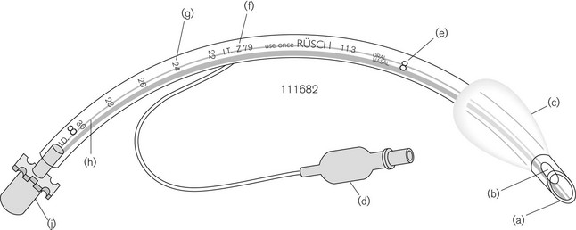
Design
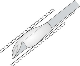
An orotracheal tube (Fig. 6.23) usually has a preformed curve that approximately matches the anatomical curve of the airway. This aids insertion and ensures that when the tube is further flexed in situ, it is unlikely to kink. The distal end is cut obliquely (bevelled) so that when held in the right hand the aperture faces to the left. The bevel facilitates insertion and allows the tip of the tube to be seen passing between the vocal cords. There may be a hole (a Murphy eye) in the wall opposite the bevel. This is designed to provide a secondary port for gas movement in and out of the tube should the bevel become blocked or wedged against the tracheal wall (Fig. 6.24). Cuffed tubes, by definition, have an inflatable cuff a short distance proximal to the tube tip, which, when inflated, seals the space between the tube and the tracheal wall.

Construction materials
• They are non-irritant and are now inexpensive enough to allow single-patient use and hence sterilization at manufacture.
• As the material is usually clear, foreign bodies and blockages may be seen more easily.
• Manufacturing tolerances are much better with plastics, so that there is much less variation in the size of the lumen (most important in neonatal tracheal tubes).
• Cuffs of rubber tubes are usually thick and require high intracuff pressures to inflate them; inadvertent over-distension of the cuff may result in this pressure being transmitted to the tracheal mucosa with a risk of mucosal ischaemia or necrosis during prolonged use.
The softness of plastic tubes is dependant on several factors. Polyurethane compounds tend to be softer and more springy than PVC, but are more expensive to manufacture. Chemicals called plasticizers may be added to PVC during manufacture to produce a softer product. The most widely used plasticizers are a group of chemicals called phthalates (particularly dioctyl phthalate in medical products). In recent years concern has been raised at governmental levels in both Europe and America about the effects of phthalates which may leech out of the plastic and some consider to be potentially “carcinogenic, mutagenic and reprotoxic”.2 While the level of risk posed by these additives is likely to be very low, several organizations seek their complete removal from manufacturing processes. More expensive plasticizers without such risk are available and in some countries are increasingly used. Silicone rubber (polymethylsiloxane) is an entirely synthetic material containing no latex derivatives, it is both soft and has the advantage that it will withstand autoclaving and therefore can be reused. It is, however, significantly more expensive and is not generally used for disposable airway products. Siliconized plastic refers to a PVC material incorporating a very small amount of silicone oil to form a surface monolayer, with the aim of altering the surface characteristics of the product, for example, to decrease surface adhesion. These tubes tend to be pearlescent or opaque. Siliconized plastic has been used in several single-use LMs to improve performance characteristics.
The type of plastic used in the construction of tracheal tubes is tested to make sure that it is non-irritant. Tubes were at one stage marked with a test number (Z79-IT), which denoted Implant Testing according to the Z79 Toxicity Subcommittee of the American National Standards Institute set up in 1968 in the USA, which established the test method (Fig. 6.23). The test consisted of implanting four samples of the plastic, under sterile conditions, into the paravertebral muscle of anaesthetized rabbits along with two samples of Reference Standard Negative Control plastic for 70–144 h. The implant sites were then examined for signs of inflammation. CE marking now denotes compliance with the essential requirements of the Medical Devices Directive (see Chapter 28).
Size
Adults
• When controlled ventilation is used the ventilator, rather than the patient, does the work of breathing. The diameter of the tube does not determine airway pressures distal to it unless the tube is so narrow as not to allow sufficient time for passive exhalation. Tube sizes of 6.5 and 6.0 mm ID do not cause a rise in end-expiratory pressures when used for ventilating adult males and females.60,61
• Small tubes are easier to insert and reduce the trauma of intubation.
• The larger the tube, the greater the area of contact between it and the vocal cords and the greater the likelihood of injury. Hoarseness and the incidence of sore throat is increased dramatically with tubes of greater than 7.0 mm ID.62 Abnormalities on CT scans of the larynx are visible at 6 months in a high proportion of patients after even short periods of intubation.63 Patients extubated following the use of small soft tubes are immediately able to phonate.
• Even in spontaneously breathing patients, the use of now mandatory continuous capnography, by virtue of being able to demonstrate failing ventilation, allows greater latitude in the selection of tube size. The work of breathing through 6.0 mm ID tubes is not greatly increased64 and ventilation is only marginally reduced with no change in functional residual capacity.65
• In the event of difficult laryngoscopy a small tube has further advantages. Smaller tubes fit more closely on a bougie or introducer with reduced likelihood of impaction of the bevel on the structures of the rima glottidis, resulting in less trauma and easier passage of the tube.
Table 6.3 gives the classical view of tubes and lengths.
Table 6.3 The classical view of the relative dimensions of tracheal tubes
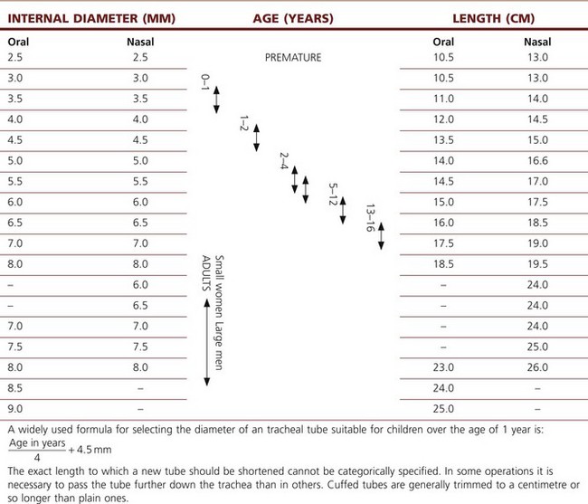
Children
In pre-pubescent children, the narrowest part of the airway is the cricoid ring. As this is nearly circular it may form a partial seal with the tracheal tube. A small degree of oedema in the paediatric airway will reduce the lumen of the trachea considerably (1 mm of circumferential swelling reduces the diameter of the adult airway by less than 10% and that of an infant by as much as 30%) and may lead to respiratory compromise. Because of these considerations paediatric tracheal tubes have traditionally been uncuffed and use of a tube small enough to leave an audible leak is still standard. Use of uncuffed tubes leads to an unpredictable leak so children have routinely been ventilated with pressure-control ventilation (ensuring ventilation despite a variable leak), while volume-controlled ventilation has been favoured in adults (delivering an assured minute volume despite changes in lung compliance).
Tracheal tube cuffs
High-pressure cuffs
In the era of red rubber tracheal tubes the requirement to sterilize the tubes by autoclaving for reuse necessitated construction that was strong and resilient. As a result tracheal tube cuffs were made of a relatively low compliance thick rubber. Repeated cleaning and reuse could lead to either hardening of the cuff making it ever more rigid or, occasionally, the development of weaknesses which if overinflated could ‘herniate’ over the tip of the tube and occlude it (Fig. 6.25). These cuffs required a high pressure to distend them and were relatively low volume (high-pressure low-volume cuffs). Thick-walled cuffs also tend to inflate in a circular shape rather than conforming to the shape of the (non-circular) trachea within which they lie. In order to achieve enough contact with the tracheal wall and a good seal relative over-inflation was required, with the result that the high pressure within the cuff was transmitted to the tracheal wall. This readily led to a reduction of mucosal pressure to critical levels (capillary perfusion pressure is usually about 35 mmHg) and if prolonged could lead to mucosal ischaemia which in turn in a proportion of patients caused the development of tracheal scarring and tracheal stenosis.
Medium-pressure cuffs
Low-pressure or high-volume cuffs
These are made from a thin inelastic material (PVC) which when fully inflated would have a larger volume than that required to effect a seal (Fig 6.26). In situ there is a large area of contact between the cuff and tracheal wall before full inflation of the cuff. The pressure within the cuff can therefore be kept much lower and can achieve a seal with minimal risk of occluding mucosal blood flow. Both medium- and low-pressure cuffs are made of very thin materials which may be ruptured by over-distension or more often damaged by snagging on teeth, instruments or passage through the nose. Low-pressure designs now predominate. This is particularly so in tubes such as tracheostomy tubes used for long-term ventilation on intensive care units.
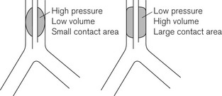
Figure 6.26 High- and low-pressure tracheal cuffs. Medium-pressure cuffs have a profile between these extremes.
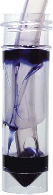
One drawback of the low pressure cuff is that because the cuff material is not fully unfolded when a seal is achieved, a number of small folds (micro-folds) can create small channels (micro-channels) running the length of the cuff. These channels may contribute to the causation of ventilator-associated pneumonia (VAP) by allowing transmission of potentially infective pharyngeal contents past the cuff. It is readily demonstrated in vitro (Fig 6.27) that these micro-folds are not waterproof and despite the mantra of the tracheal tube ‘protecting’ the airway it must be acknowledged that this protection is incomplete. There is increasing interest in the role of micro-aspiration in VAP amongst patients on intensive care.
Nitrous oxide and tracheal tube cuffs
• the permeability of the material from which the cuff is constructed (rubber being more permeable than plastic)
The rise in intra-cuff pressure caused by this diffusion into the cuff depends on the compliance of the cuff. Low-volume high-pressure cuffs suffer the greatest pressure rise and may well transmit this pressure rise to the tracheal mucosa. High-volume low-pressure cuffs expand with only a slight increase in pressure until full inflation; at this point, owing to the inelasticity of the material, the pressure may rise rapidly to up to 12 kPa (90 mmHg). This can damage the tracheal mucosa.67 In practice equilibration takes place over approximately 20 minutes, so checking the cuff pressure after 20 minutes will minimize problems. Should the anaesthetic gas mixture be changed at a later time to increase (or decrease) the fractional concentration of nitrous oxide, further diffusion into (or out of) the cuff will occur.
• The Mallinckrodt Brandt device has a large pilot balloon made from a material that allows nitrous oxide which has diffused into the cuff to escape (Fig. 6.28).
• The Mallinckrodt Lanz (Fig. 6.29) device consists of a special control valve and pilot balloon arrangement. A compliant latex balloon, protected within a larger open plastic covering, connects to the cuff via a flow restrictor. Insertion of a syringe into the valve bypasses this restriction allowing rapid inflation of the cuff. Thereafter, gradual volume changes in the cuff are buffered by the pilot balloon. When filled with a preset volume the device regulates the cuff pressure to between 20 and 25 mmHg.
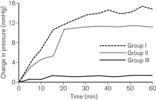
• Portex Soft Seal cuffs are made of a PVC material using a higher molecular weight plasticizer, which results in a five-fold lower permeability to nitrous oxide. Fig. 6.30 compares rises in intracuff pressure between a Soft Seal and two other cuffs during 1 hour of anaesthesia using 66% nitrous oxide.
• The Bivona ‘Fome-Cuf’ uses a piece of shaped foam to replace the air within the cuff. Prior to insertion the cuff is evacuated to collapse the foam and after insertion the pilot tube is opened to the atmosphere to allow the foam to expand, to ‘inflate’ the cuff (Fig. 6.31). Because the pilot tube is left open, diffusion of nitrous oxide does not further inflate the cuff. The pilot tube may also be connected to the ventilation circuit to equilibrate intracuff pressure with proximal airway pressure during positive-pressure ventilation.
Nasotracheal intubation
The flexible LMA has removed the need for nasal intubation for many cases in which it has been traditionally used. In some centres uncuffed nasal tubes remain popular for use in adults using spontaneously breathing techniques, such as for short dental cases. The larynx is packed to protect the lungs for the period of the surgical procedure, and afterwards the small soft tubes cause minimal irritation and can be removed once the patient has woken. The necessity to use the highly error prone throat pack is a potential disadvantage. They increase the incidence of sore throat but, more importantly, in spite of many years of use anaesthetists and surgeons still contrive to devise seemingly new and exotic circumstances and procedures for forgetting to remove them in order to cause postoperative airway obstruction.69
The design of the bevel is also important; sharp long bevels have tended to be replaced by short bevels with rounded tips (Fig. 6.32) which are less likely to snag on obstructions. Some manufacturers even use a different softer compound for the leading edge of the tracheal tube.
Common problems with the use of tracheal tubes
Many of the problems, particularly relating to tube kinking or obstruction by external compression, are now rarely seen with the use of PVC tubes. These soften with warming when in use, appearing more often to remould rather than kink abruptly: so much so that specially designed non-kinking tubes, such as the Oxford tube and even the ‘armoured tube’ are now largely obsolete (see below). Some of the common problems are:
• Disconnection of the tube from the 15 mm ISO connector or of the connector from the catheter mount is common. This is most likely during shared airway or head and neck surgery. With the patient’s head often positioned away from the anaesthetist and hidden by drapes and surgeons, vigilance and appropriate monitoring (which includes alarm-enabled capnography) is vital.
• Leak. In uncuffed tubes excessive leak indicates a larger tube is required. With cuffed tubes a leak may arise if the cuff is at the cords. It may also indicate inadequate cuff inflation or deflation caused by cuff damage, over-inflation or a fault in manufacture.
• Kinking external to the patient. Tubes are prone to being kinked by the position of the breathing system, e.g. an uncut tube emerging from the mouth or as in Fig. 6.33, due to rotational forces being applied by a breathing system. Paediatric tubes, which have thinner walls and are connected to relatively heavy attachments, are particularly prone to this, especially when softened by warm respiratory gasses.
• Kinking inside the patient (Fig. 6.34). Modern PVC tubes are fairly resistant to this form of obstruction. If a tracheal tube must be bent acutely when in situ, a reinforced tube or one that is specially shaped should be used (see below, Tubes for special purposes). When the airway is shared with the surgeon, tube kinking and extubation or disconnection are increased problems. The Boyle-Davis gag used for tonsillectomy, if used without care or experience or with the incorrect blade size, frequently causes kinking (and/or inadvertent extubation on removal, and can advance an overly long tube into the bronchus). Obstruction by biting is a risk as a patient emerges from anaesthesia. Red rubber tubes were prone, especially after repeated autoclaving, to obstruction by a tightly inserted throat pack or even by inward herniation of the tube wall underneath the high-pressure cuff.
• Foreign bodies. All manner of foreign bodies have been found within airway devices causing blockage. Tracheal tubes (and other airways) should not be placed in the same dish as Luer-Lock caps, needles and ampoules etc., even after use. Diaphragms of dried mucus and even K-Y jelly, which may be virtually invisible, have also been found blocking tubes. In single-use devices, this danger has been superseded by diaphragms of clear plastic being formed across the openings of tubes when, for unwrapping, they are pushed through their plastic packaging. The invisible film is then kept firmly in place by the connector when the next item in the sequence is attached. Rarely manufacturing defects may lead to devices with similar occlusions. Standard checking of the breathing system will detect obstructions only as far as the final patient interface. There is often a presumption that tracheal tubes (or SADs) are patent; visual inspection of all such devices before use, and a high index of suspicion during use, is mandatory to prevent rare but potentially fatal problems.
• Distal obstruction can occur in several ways. The opening may be occluded if the larynx or trachea is deviated to one side by pathology (e.g. Fig. 6.24) or by surgical displacement (e.g. during thyroidectomy). It is also seen if the tube is advanced too far into the right main bronchus (Fig. 6.35). This pattern of obstruction may be more evident in expiration than inspiration. The presence of a Murphy eye may counteract such problems.
• (Endo) bronchial placement. A tube may be passed too far down the trachea and enter a main bronchus (usually, but not always, the right). This can occur after correct placement when the head and neck is repositioned; extension of the head and neck tends to advance the tube. It is a particular problem when using tubes of pre-formed length (e.g. RAE tubes) and in children. During laparoscopy, bronchial intubation may also occur as the carina rises upwards with diaphragmatic displacement caused by pneumoperitoneum.
• Extubation. Short, uncuffed and preshaped tubes (a combination of which is commonly used in children) are particularly prone to inadvertent extubation. Head and neck movement and surgical interference are additional triggers.
ISO connectors, angle pieces and catheter mounts
ISO connectors
The tracheal tube is attached to the other components of the breathing system by a male 15 mm ISO (International Organization for Standardization) tapered connector (Fig. 6.23J). This connector itself fits into the tracheal tube via a tapered cone producing a secure connection. In PVC tubes with nylon/PVC connectors, because of the surface characteristics of the materials (stiction), the seal often can only be broken by cutting the tube. Tubes are therefore supplied from the manufacturer with the connector only lightly inserted so that the tube may be cut to length.
Connectors and angle pieces
• streamlining the fit in order to improve surgical access around the head and neck of a patient
The connector with the female counterpart to the 15 mm ISO connector at the proximal end of the tracheal tube may be a simple angle piece designed to also fit the 22 mm female taper of a facemask, or it may allow other functionality (Fig. 6.36).
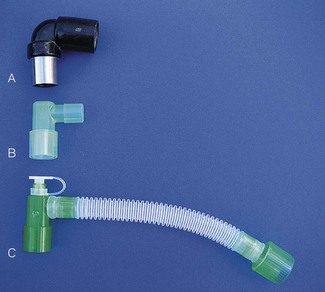
These connectors may serve a variety of functions (Fig. 6.37), for example:
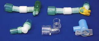
• swivel connectors to reduce torsion on the tube
• sealed ports enabling introduction of a flexible fibreoptic scope through a gas-tight seal.
A smaller standard of 8.5 mm is available for paediatric tubes to reduce component weight (see Chapter 12).
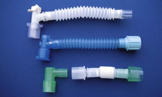
Catheter mounts
Before the introduction of the Boyle’s machine – the forerunner of the current anaesthetic workstation – and the Magill breathing attachment (the first Mapleson A system) the mixed gasses, with added vapour of volatile agents, were fed via a narrow bore tube (catheter mount) to the patient, with no reservoir bag or expiratory valve in the positions in which we now find them. The end of the tube could be attached to an airway device, such as the Boyle-Davis gag or to a catheter that was passed through the larynx into the trachea. In the latter case, the gasses and/or vapours were blown constantly down the catheter and were exhausted to the atmosphere by passing back through the trachea but outside the catheter (see above, under History).
Currently, a catheter mount usually consists of a short piece of flexible kink-resistant 15 mm tubing with a 15 mm ISO female tapered connector for attachment to the tracheal tube (Fig. 6.38). The other end of the catheter mount may have either a 15 mm ISO male taper or a 22 mm ISO female taper connector for coupling with the breathing system. Although the device increases the apparatus dead space of the breathing system, the flexibility it imparts makes this an insignificant consideration except in the very young.
Tracheal tubes for special purposes
RAE preformed tubes
There are two separate versions of these tubes, named after their inventors: Ring, Adair and Elwin (Fig. 6.39). The tube for oral intubation has a preformed bend on the part of the tube where it exits the mouth, so that proximal tube passes down the chin and away from the face, thus improving surgical access to the mouth, nose and head of the patient. The nasal version is bent where it exits the nose so that the part housing the ISO connector passes upwards to the forehead. It is used to improve surgical access for intra-oral procedures.
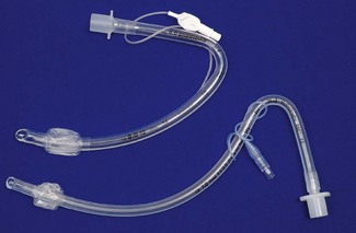
The main disadvantage of both designs is that the bend in the tube determines the length of tube that lies within the patient. As patients inevitably vary in size the tube may be too long for a given patient leading to the tip entering the bronchus; this is a particular problem with small children. Conversely, and much more commonly, with the trend towards using smaller calibre tubes, because tube dimensions have not been reformulated, a chosen RAE tube may be too short to reach comfortably below the glottis, increasing the risk of inadvertent extubation (see above: Tracheal tubes, Size). This is a particular problem with the newer cuffed paediatric tubes where manufacturers appear to have simply added a cuff to existing tubes rather than reformulating the proportions.
Reinforced tubes
These tubes are usually supplied at a length of 30 cm or greater for an ID of 5.0 mm and above. The reinforcing spiral will not stretch to accommodate a connector so the tubes cannot be cut to a shorter length than supplied. The ISO connectors are therefore usually bonded at production to a non-reinforced part of the tube. Special care must be taken not to insert these tubes too far. Reusable latex versions were particularly prone to kinking at the ‘soft spot’ between the end of the connector and the start of the spiral reinforcement (Fig. 6.40).
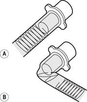
Polar tubes
Portex (Smiths Medical), in their Ivory range of tubes, manufacture a tube for nasotracheal intubation in a soft PVC material (see Tracheal tubes, Materials) with a preformed curve that takes the proximal end of the tube snugly along the nose and over the forehead (Fig. 6.41). These tubes are well-suited to maxillofacial surgery as they impinge relatively little on the surgical field. If access is also needed to the forehead, as in some cosmetic or reconstructive plastic procedures, the proximal end can be swung down without the tube kinking, to descend over the cheek or chin. The soft plastic of the Ivory range is relatively atraumatic in the nose, which in combination with the springiness of these tubes makes them ideal for ‘blind nasal intubation’. Interestingly, the material, originally called ‘Vinyl Portex Tubing’, was actually first developed in 194466 as a substitute for the red rubber tubes whose primary materials were in short supply.
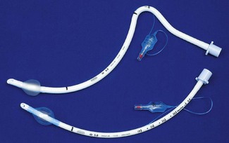
These tubes, in sizes 6.0 and 6.5 mm ID, are a good choice for nasal fibreoptic intubation, in spite of the reservations previously mentioned regarding cuff sizes and small tubes (the length and cuff size in this case is usually adequate, even for the largest adults).
Microlaryngeal tube
This tube (Fig. 6.41, lower) has a small internal diameter (ID usually around 4.5–5.5 mm) but an adult-sized high-volume low-pressure cuff. The tubes are designed to be unobtrusive in the larynx so as to allow surgery around the vocal cords and are long enough for nasal intubation. The high resistance to gas flow in these tubes virtually obligates controlled ventilation and a long expiratory phase should be used to allow complete expiration. Due to their flexibility they can be difficult to insert unless Magill intubating forceps are used. Standard adult-sized bougies and stylets are usually too large to pass through these tubes. Despite their suitability for laryngeal surgery they tend to lodge in the anterior of the laryngeal inlet so do not provide surgical access for all laryngeal lesions. As they are not laser resistant they are unsuitable for such surgery.
Carden tube
This tube was developed to facilitate microsurgery of the larynx. It is rarely used now but may perhaps enjoy a resurgence for jet ventilation. It comprises a shortened cuffed tracheal tube that sits wholly below the glottis attached to a long catheter for insufflation of gas and a long pilot tube for the cuff (Fig. 6.42). It may be inserted by grasping the tube with Magill’s forceps and placing it under direct vision. Alternatively the Carden tube and an uncut plain tube, just wide enough to fit inside it, are threaded onto a stylet. This assembly is introduced through the larynx so that the Carden tube and a centimetre or so of the plain tube pass into the trachea. The cuff of the Carden tube is inflated, the stylet is withdrawn and anaesthesia is maintained in the usual manner through the plain tube. For laryngoscopy, the plain tube is removed as is the breathing system, and gasses are delivered directly to the Carden tube through a feed mount. The expired gasses escape via the lumen of the Carden tube.
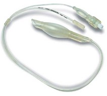
Tubes for laser surgery
Mallinckrodt ‘Laser-Flex’ tracheal tubes
These single-use tubes for oral intubation are made from a gas-tight metal helix with the pilot tubes for the double cuff carried within the lumen of the airway (Fig. 6.43). It is advised that the cuffs, which are not laser resistant, are inflated with saline, ideally dyed with some methylene blue, to prevent ignition of the cuff and so that puncture is obvious. The function of the proximal cuff is to protect the distal cuff and the tube must be replaced if either cuff is defective. The surface of the tube shaft reflects a defocused laser beam with a lower potential for causing tissue destruction. The tip of the tube is made of a soft plastic for a more atraumatic insertion. The tubes have a markedly reduced inner diameter when compared to PVC tubes of the same outer diameter and care must be taken to allow adequate expiratory time in ventilated patients.
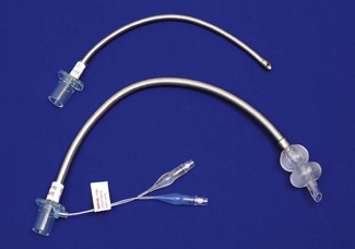
Foil wrapped
An alternative approach used by some manufacturers is to spirally wrap a suitably small rubber tube with a narrow strip of silver or copper foil (this may be stippled or corrugated to disperse an incident beam) (Fig. 6.44). The tube is then overwrapped to give a smooth outer coating. The Rusch Lasertubus is covered in Merocel foam (a porous sponge), which is soaked in saline to help absorb laser energy. This tube is provided with a double cuff arrangement.
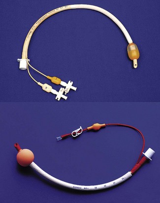
Tubes and catheters for ‘jet ventilation’ (high-pressure source ventilation)
Supraglottic ventilation
If surgical access is significantly impaired by a laser resistant tube, the surgical laryngoscope that is used to suspend the larynx for surgery can be fitted with a metal cannula (Fig. 6.45) that ends above the glottis and can be used for ‘jetting’ with high-pressure gas (supraglottic ventilation). Anaesthesia must be maintained intravenously. The quality of ventilation depends on the surgeon placing the tip of the ventilating catheter above and in line with the trachea and requires careful co-operation between anaesthetist and surgeon (Fig. 6.46). Alternatively, high-pressure source ventilation may be delivered by a small laser-resistant catheter passed through the glottis (transglottic ventilation).
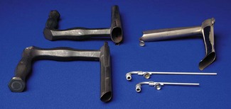
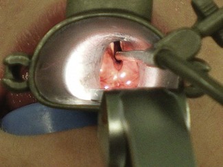
Transglottic ventilation – Hunsaker tube
The Hunsaker Mon-Jet Ventilation tube (Fig. 6.47) (Medtronic Xomed, USA) is a narrow-bore dual lumen tube designed for transglottic high-pressure source ventilation that allows concomitant airway pressure monitoring or gas sampling from the narrower second lumen. The 33-cm-long device (4.5 mm at its widest diameter) is made of a laser-resistant fluoroplastic and ends in a moulded plastic cage which aims to centralize the discharged jet stream and prevent direct impingement on the tracheal wall mucosa. In combination with a dedicated jet ventilator, such as the Accutronic Medical Systems Monsoon or Mistral models (see Chapter 9), this device offers improved surgical access for unhurried instrumentation and laser surgery of the major airways. Unlike the microlaryngeal tube the Hunsaker tube can be easily positioned to allow the surgeon access to any part of the larynx. Because the above ventilators check that airway (pause) pressure is below a pre-set limit before each inspiratory phase even at high cycle rates, jet ventilation can comfortably and safely continue up to and beyond patient arousal at the end of surgery.
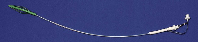
Subglottic ventilation: transtracheal catheters
The use of small tubes requires a high pressure gas source for ventilation. This may be a manually operated, fixed-pressure ventilator (Sanders injector, 4 bar); a manually operated, variable-pressure ventilator (Manujet, 0.5–4 bar; see below) or an automatic ventilator. Mechanical ventilators may be of a variety of degrees of sophistication and may provide conventional ventilation, high-frequency ventilation or a combination of the two. The use of a high-pressure source introduces a significant risk of barotrauma (particularly with manual techniques) and this risk increases if the larynx closes or if expiration (which occurs passively through the native airway) is not scrupulously confirmed before each inspiration.70,71 Ventilators with airway pause pressure monitoring linked to ventilator cut-outs (see above) are safer and their use is recommended.72
Laryngectomy tube
Conventional tracheal tubes placed through a tracheostomy in patients undergoing or with previous laryngectomy are difficult to fix in place and prone to kinking or slipping down into a bronchus. The ‘U’ shape of the laryngectomy tube (Fig. 6.48) means it sits unobtrusively on the chest wall with the long straight proximal portion allowing direct connection to a breathing system distant from the operative site. The internal portion of the tube is short and the tip is usually cut close to the cuff to minimize the risk of bronchial intubation.
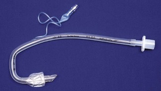
Tubes for thoracic surgery (including bronchial blockers)
Tubes with bronchial blockers
The second method of isolating a lung is to use a tracheal tube through which a fine balloon catheter can be passed either via the lumen of the tube or through a channel in its wall. The balloon tip is then passed, usually with the aid of a flexible endoscope, into the intended main bronchus, which becomes isolated when the balloon is inflated (Fig. 6.49). A central channel which opens beyond the balloon allows suction to deflate the lung and may also be used to augment oxygenation by ‘insufflation’ into the collapsed lung. In the past Foley catheters and Fogarty embolectomy catheters have been used in place of bronchial blockers but improved construction of bronchial catheters obviates this need.
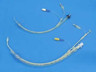
Bronchial blockers have a variety of designs to assist placement; these include fixed angulations, loops for attachment to an endoscope and a novel design with dual balloons either side of a self-deploying ‘V’ (Fig. 6.50). In this latter design the blocker is introduced within a sheath to the carina then advanced beyond the sheath, so the ‘V’ opens up and inevitably straddles the carina, with the dual balloons enabling deflation of either lung as required.
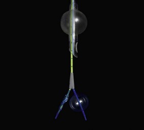
Double lumen tubes
The third method is to use a combination or double lumen tube (DLT) (Fig. 6.51). These are formed by bonding together two tubes of similar diameters but different lengths. The shorter tube ends in the trachea and seals this with one cuff, whilst the longer tube is designed to fit a main bronchus and seal this with a separate cuff. The cuffs are supplied by separate inflation tubes and pilot balloons, which are marked and colour-coded to aid identification. DLTs are produced in left- and right-sided versions. Some designs have a small soft carinal hook to prevent over-insertion of the tube but this is uncommon in modern single-use versions. Because the opening of the right upper lobe bronchus is so close to the origin of the main bronchus, the bronchial lumen on right-sided versions also has a side hole and a cuff that is designed so that it does not occlude this (Fig. 6.52). The bronchial cuff and inflation tube are blue by convention.
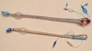
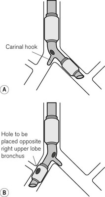
Sizes
The combined size of the two lumens makes the device bulky and prevents its use in children. Because the external shape of the device is circular in cross-section, the lumens of the two tubes are each ‘D’-shaped and the size cannot be quoted in terms of an internal diameter. Sizes are quoted in French gauge (Fr). This scale is constructed from the external diameter of the widest part of the device, measured in millimetres, multiplied by a factor of 3 (corresponding roughly to the circumference). Usual sizes are 28, 35, 37, 39 and 41 Fr; many designs offer only one or two sizes.
Tubes to assist intubation
The Mallinckrodt Endotrol tracheal tube (Covidien, Ireland) has a control wire connected to the distal tip that runs in the wall of the tube on the inner aspect of the curvature. Traction on this wire increases the curvature at the tip of the tube to facilitate intubation. This device is no longer available in Europe.
The Intubating LMA tracheal tube (Intavent Direct, Maidenhead, UK) (Fig. 6.15), which is produced both in reusable and single-use versions, is a valuable tube for use in difficult intubations. It is a reinforced silicone tube with a soft bullet-shaped silicone tip. This tip dramatically reduces the likelihood of impingement on the arytenoids (a common problem with conventional tracheal tubes) and largely eliminates ‘hold-up’ of the tracheal tube during insertion. This reduces failure, speeds insertion and minimizes the likelihood of laryngeal trauma. Although it was designed for use with the ILMA its performance characteristics make it also suitable for use with catheter exchange techniques and with a flexible endoscope.
Tubes with additional ports/lumens
LITA tube
The extra lumen in this tube has ten small side holes, eight above and two below the cuff for the ‘Laryngotracheal Instillation of Topical Anaesthetic’. There is evidence demonstrating better tolerance of intubation in sedated patients73 and conflicting evidence regarding suppression of response to extubation73,74 (Fig. 6.53).
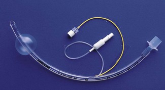
Developments in tracheal tube and cuff technology for intensive care
Cuffs made of silicone or polyurethane are available that eliminate microfolds without the need for high intracuff pressures. Use of continuous electronic cuff pressure measurement and ‘servo’ technology enables a user-defined intra-cuff pressure to be maintained continuously, even during patient movements: a common cause of cuff leaks (e.g. Venner PneuX P.Y., Intavent Direct, Maidenhead, UK). A tapered (conical) shape to the inflatable tracheal tube cuff may be effective in preventing it developing folds and microchannels across the full contact surface with the tracheal wall (Mallinckrodt TaperGuard tracheal tubes, Covidien, Ireland).
Finally antimicrobial agents (such as silver nitrate or elutable agents) may be incorporated onto the surface of into the fabric of the tracheal tube.75,76
Subglottic devices
Tracheostomy tubes
There are many varieties of tracheostomy tubes (Fig. 6.54) and only some of the features are detailed below. At least one manufacturer, Rüsch, will tailor single tubes for individual requirements. For intensive care and theatre use simple tubes are appropriate. It has become conventional when tracheostomies are used outside critical care areas and in the community to insert a tube with a liner. A liner is a usually plastic tube that lies within the main tube: as it reduces the internal diameter of the tracheostomy it is not suitable for patients with very limited respiratory reserve. The advantage of a liner is that it can be easily removed for claning of secretions without having to remove the tracheostomy tube itself. When a liner is not used humidification and nursing care must be of a high standard to prevent the build up of secretions.
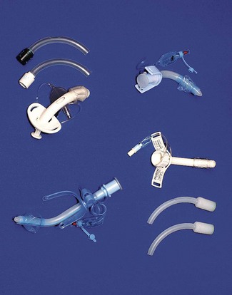
• Cuffed/uncuffed. In children and in adults, where positive-pressure ventilation is not required and the risk of aspiration is not increased, a plain uncuffed tube may be used to maintain the stoma. These may be suitable for long-term use where there is no risk of aspiration (i.e. good bulbar function and good cough).
• Fenestrated/non-fenestrated. Fenestration of the tube (a hole that lies below the larynx when the tracheostomy is in place) allows exhalation through the glottis for the purpose of vocalization. Use of a non-fenestrated inner tube in a cuffed fenestrated tube permits positive-pressure ventilation where required. Care must be taken to ensure the fenestrated part of the tube lies within the trachea and not in the pre-tracheal tissues.
• Long stem/flanged. In patients with significant swelling or pathology about the head and neck (e.g. patients with burns) ordinary tracheostomy tubes are often too short to reach the trachea. Many manufacturers produce long-stemmed tubes, usually with an adjustable flange (Fig. 6.54) and sometimes in conjunction with an armoured tube wall design, allowing the tube to bend where required rather than having a fixed preformed curve.
• Foam cuff, Lanz device, Brandt device. These are available as with normal tracheal tubes as strategies to deal with the problems of cuff seal pressure within the trachea (see above, Tracheal tube cuffs).
• Above cuff suction/vocalization. A soft catheter ending above the tracheal cuff may be bonded to the tube to permit suction removal of secretions that tend to pool in the larynx and which may contribute to ventilator associated pneumonias. A similar design can be used to insufflate air to permit vocalization even during positive pressure ventilation.
• Distal pressure monitoring. A narrow bore tube ending distal to the cuff allows direct measurement of tracheal pressures.
• Speaking valves. The tube may be capped with a one-way valve that allows gas to enter on inspiration but prevents gas passage on expiration. Provided the cuff is deflated expiratory gas is redirect through the larynx which allows vocalization. If the cuff is inflated the valve must be removed.
[/level-membership-for-anesthesiology-category][not-level-membership-for-anesthesiology-category]
Chapter 6 Airway management equipment
Standards, techniques (and fashions) in airway management have changed considerably over the last two decades. Although the most basic principle of anaesthesia is the maintenance of a patent airway aimed at providing adequate oxygenation and ventilation, the range of devices and products used has seen major changes especially in the focus of the designs. Of the developments in the last decade several are notable.
Numerous alternatives to the LMA have since been developed. These devices which sit outside the larynx and aim to provide a gas-tight seal are now generally referred to simply as supraglottic airways or SADs (supraglottic airway devices): the term extraglottic airway is more anatomically accurate but is not widely used.1 The number and variety of SAD designs have expanded dramatically in the last few years with the result that there are numerous products that vary considerably in materials and performance. Many of these are single-patient use laryngeal masks designed to compete for the market share of the original LMA. Nonetheless several newer SADs offer genuine advances in versatility, efficacy and safety.
Finally, overlying all the above considerations; concern about the transmission of infective agents, particularly those responsible for variant Creutzfeldt–Jakob disease (vCJD), has been the apparent driving force behind an increasing trend towards reliance on single-use airway devices. This trend, whether based on science or not (of which more later) has meant that the majority of airway devices now being developed are at least in part single-use. Production and material costs and hence price, as well as storage and stocking issues, are ultimately more significant considerations for single-use items and this is already affecting the range and quality of equipment available in many hospitals.
Fundamentals
The fundamental principle of airway management during general anaesthesia is that:
1. a clear airway must be established and maintained allowing free passage of gasses to and from the patient’s lungs. Failure to do this is likely to lead to collapse of the airway at pharyngeal or laryngeal level. Without intervention airway obstruction is inevitable and if not correctly managed, will be followed within minutes by hypoxia, brain damage and death.
Materials used in airway devices
Plastics
The most common plastics are polyethylene and polyvinyl chloride (PVC). Polyethylene is cheap, fairly pliable, non-allergenic and can be moulded easily. It is ideal for breathing hoses, connectors and hypodermic syringes but not for the manufacture of reusable items as it will not withstand autoclaving and components may deform with repeated use. It is unsuitable for tracheal tubes (see below) as other materials cannot be easily welded or glued to its surface (e.g. cuffs). For this purpose, PVC is more suitable. PVC is brittle on its own but can be made in varying degrees of softness by the addition of plasticiszers (see below). Concerns have been raised in some areas about potentially toxic chemicals in PVC called phthalates and the potential production of both phthalates and dioxins when PVC is disposed of or incinerated.2
Materials used in tracheal tube construction are described in more detail below (p.156)
Artificial airways
Terminology
The term airway (or anatomical airway) will be used to describe the air passages within the subject, including and beyond the nasal and oral openings. The term distal refers to the part of the airway or device furthest into the subject’s airway and the term proximal to the part emerging or closest to the mouth or nose. Artificial airway then is any device that aims to maintain patency of any of the air passages. Artificial airways may be:
• simple airway adjuncts, such as the oropharyngeal and the nasopharyngeal airways. These may not be sufficient to maintain the patency of the airway on their own and may require the patient’s jaw to be supported as well. Although these are strictly speaking supraglottic devices in that their distal orifice lies above the glottis, in general usage the term SAD is not used to encompass or imply these simple airways.
• supraglottic airway devices (SAD) such as the laryngeal mask airway (LMA) and many others which aim to maintain patency of the airway on their own
• infraglottic devices, which are airway devices whose distal part lies below the glottis. Therefore they include all tracheal and tracheostomy tubes, jet ventilation catheters and cannulae, and bronchial blockers. It is a lesser used term.
Simple airway adjuncts
The maintenance of a clear airway in an anaesthetized patient can often be achieved by a simple elevation of the jaw (jaw thrust) and/or extension of the head on the cervical spine. These movements tend to separate the tongue, epiglottis and soft palate from one another and away from the posterior pharyngeal wall (Fig. 6.1). However, in many patients maintenance of the airway in this manner is either ineffective or impractical for surgery. Patients with anatomical reasons for such manoeuvres to fail include those whose ‘pharyngeal spaces’ are absolutely or relatively small (e.g. a large tongue, small lower jaw, large diameter neck, obesity and also those with large adenoid or palatine tonsils). In such patients the obstruction must be relieved and the easiest way to achieve this is by inserting a device that separates these structures and thus creates an artificial airway. These airway adjuncts may be inserted via the mouth (oropharyngeal airway) or via the nose (nasopharyngeal airway) (Fig. 6.2).
Oropharyngeal airway
These devices are shaped to emulate and so restore the space present in the pharynx during consciousness by pushing the tongue and epiglottis away from the posterior pharyngeal wall. Oropharyngeal airways are usually oval-shaped, occasionally circular, in cross-section and are produced in varying lengths and diameters to suit different patient sizes from premature neonate to large adult. The proximal end has a flange to limit the depth of insertion and prevent its loss into the pharynx. Devices are sufficiently rigid to prevent collapse should the patient bite down and indeed they may be used as a ‘bite block’ in an intubated patient (to prevent airway obstruction as a result of the tracheal tube being obstructed by biting). When inserted, the distal end should lie at the posterior of the tongue but above the epiglottis. Insertion too deep may in itself lead to airway obstruction either by mechanically pushing the epiglottis back or by irritating the sensitive laryngeal inlet leading to laryngospasm. There is a standard colour and number coding for size. The most popular oropharyngeal airway type is the Guedel pattern (Fig. 6.3). To select the correct size of Guedel airway, the distance from the flange to the distal tip of the airway should be about the same as from the patient’s lips to the tragus of the ear.
Complications
Oropharyngeal airways for flexible endoscopic oral intubation
A number of airways have been devised to assist oral intubation. When used to aid flexible endoscopic intubation they serve to deliver the endoscope behind the tongue, and as close to the larynx as possible, ideally having bypassed any secretions. Their shapes are broadly similar to the Guedel airway but often describing a fuller curvature along the length and with a more circular cross-section (Fig. 6.4).
The Berman airway (originally designed to assist blind oral intubation and pharyngeal suction), like the VBM and Ovassapian (not pictured) airways is open along one side. These devices when used for endoscopic intubation are removed before passage of the tracheal tube. The fully enclosed Optosafe airway has a large enough diameter to accommodate a tracheal tube.
The airways also act as a ‘bite block’ preventing damage to expensive fingers or delicate endoscopes (see also: Flexible endoscopes, conduit airways). This purpose is better served by the use of a dedicated bite block such as the BreatheSafe (Fig. 6.5) which more resembles a dental prop and allows full access to the oral cavity while preventing mouth closure.
Nasopharyngeal airway
The nasopharyngeal airway is designed to be passed through the nares and along the floor of the nose to deliver the tip beyond the soft palate to lie in the oropharynx, above the epiglottis. It can bypass nasal, soft palate and tongue base obstruction. The tubes have either a fixed or adjustable flange (Fig. 6.6) at the proximal end to prevent loss of the device into the nose and to limit insertion of an excessive length. The tip is bevelled to make its passage through the nose less traumatic. Some designs have a hole cut in the wall opposite the bevel to maintain patency if the tip becomes obstructed. They are produced in a range of sizes with the length of the airway governed by the internal diameter of the tube.
Nasopharyngeal airways are often indicated where a patient has limited jaw opening, awkward or fragile dentition or where an oropharyngeal airway is frequently displaced by a marked overbite. They are well tolerated by patients during relatively light levels of anaesthesia and during emergence. To avoid traumatic insertion and heavy bleeding nasopharyngeal airways are ideally soft (plastic, polyurethane or latex rubber). Avoiding excessively large tubes also minimizes complications during use, but the tube must be long enough to extend well into the oropharynx. An estimate of appropriate length is the distance from the tip of the nose to the tragus of the ear.
Facemasks
Anaesthetic facemasks are designed to fit over the patient’s nose and mouth and enable the creation of a low pressure seal. This should not require excessive force. The facemask (Fig. 6.7) consists of three parts: the mount, the body and the edge. A snug fit is achieved by incorporating one or more of the following features into the design: by anatomically shaping the body, by the use of an air-filled cuff at the edge (Figs 6.8B, D and E) that has a soft cushioning effect or by a soft pliable flap (Figs 6.8A and C) that takes up the contour of the face.
The body may be made from black rubber, neoprene, plastic, polycarbonate or silicone rubber. In some cases, a malleable wire stiffener or wire gauze is incorporated in the body so that the shape may be altered to fit the patient’s face. The transparent body of a polycarbonate or plastic facemask permits continuous inspection of the airway and respiration to be monitored by the appearance of condensation during exhalation. This is useful during anaesthesia and particularly during resuscitation. A transparent facemask also affords the possibility of seeing regurgitant matter or vomitus emerging from the mouth. Such masks are perhaps less threatening to children and anxious adults (Figs 6.8C, D and E).
The internal volume (apparatus dead space) within the body of the facemask is relatively unimportant in adults but may assume significance in neonates and infants where it can constitute 30% or more of their tidal volume. Several designs shape the paediatric facemask to minimize the apparatus dead space (Fig. 6.9). In spite of this, good fit may be more important than theoretical apparatus dead space: paradoxically in paediatrics, a larger facemask particularly of the Rendell-Baker or Laerdal type, may allow the face to fit further into the mask with improved fit and reduced effective apparatus dead space.
The edge may be anatomically shaped and fitted with a cuff or flap. A good fit is essential to prevent dilution of administered gasses by room air during spontaneous respiration and to allow positive pressure ventilation without gas leak. A variety of types and sizes of facemask must be available, since none will be a good fit for every face. Edentulous or bearded patients may be especially difficult. The former are best managed by leaving any dentures in place to prevent the cheeks from falling away from the mask and by using a smaller mask. Beards often prevent a good seal around the edge of the mask and a leak-free fit may sometimes be achieved with a bigger mask held firmly with two hands. Anaesthetists have often had to go to bizarre lengths to achieve a useful seal in heavily bearded patients (e.g. using a pierced defibrillator gel pad on the face3 or even wrapping the entire head in clingfilm4). Reusable masks with a cuff have a small filling tube fitted with a plug to enable the degree of inflation to be regulated. The plug must be removed to allow the cuff to deflate if the mask is to be autoclaved.
The shift towards disposable single-use facemasks avoids the cost of sterilization (increasingly performed off-site for many hospitals) packaging, and mandatory tracking and trace systems, but risks a reduction in quality. The same principles of design nevertheless apply to plastic disposable facemasks (Figs 6.8C, D and E). Materials and components are cheaper and of lower quality, but more importantly there is a much more limited range of designs and sizes. Most, even those for paediatric use, are essentially based on the one design of air-filled cuff and cone-shaped body. As they are reproduced with differing quality and materials by numerous manufacturers, uniformity of performance cannot be assumed. They may be advertised with bold claims of high performance and popularity but formal clinical evaluation is not a pre-requisite to bringing them to market. Several new designs have been found to be substandard and it is wise to assess performance before changing devices. Sizes do not necessarily equate between manufacturers. Some single-use masks do not allow adjustment of the volume of the air-filled cuffs and these may be both under filled and of less pliable plastic leading to a poor-quality seal. Poor design or poor fit, even in the absence of a leak, can cause areas of high pressure on the skin, which if unchecked, could lead to ulceration. Single-use masks do, however, have a number of advantages beyond sterility. These include use of inert plastics (eliminating risk of allergy to latex), transparency and even the potential to add scent to the plastic making the products more readily accepted by patients.
Many anaesthesia masks are supplied with a ring device that has several lugs protruding to allow attachment of a head harness. Older black rubber masks have a similar metal harness ring (Figs 6.8A, D and E). A head harness may be used to allow facemask anaesthesia while allowing the anaesthetist to keep both hands free. Since the introduction of supraglottic airways head harnesses are rarely used, if ever, except during non-invasive ventilation (see below).
Masks for some dental anaesthetic techniques are designed to fit the nose only, so that the dentist has unimpeded access to the mouth (Fig. 6.10). They are also known as nasal inhalers.
Facemasks are also used for non-invasive ventilation (NIV) or continuous positive airway pressure (CPAP) in differing scenarios, both in and out of hospital (see Chapter 7, Fig. 7.17). These are similar to anaesthesia facemasks and may cover the mouth and nose (conventional CPAP) or just the nose (for nasal CPAP). Such masks tend to be single-patient use devices made of plastics and soft silicone rubber. They are usually of a higher quality than single-use anaesthesia masks as comfort and tolerability is the key to treatment compliance and success. CPAP masks often incorporate additional ports for valves and airway manometry and have attachments for a retention harness to keep the mask comfortably on the patient’s face.
Supraglottic airways
History
Prior to 1988 maintaining a clear airway in a non-intubated, anaesthetized patient, might well have involved elevating and protruding the lower jaw, supporting it in this position with a Guedel airway, placing a facemask over the nose and mouth and securing this with a Clausen’s (head) harness to provide a gas-tight fit: all essentially dextrous tasks requiring practised performance. Although preceded by numerous devices that were designed to control the airway without tracheal intubation, it was not until the advent of the Laryngeal Mask Airway (LMA), first described in 1983,5 and introduced commercially in 1988, that such devices achieved success in anaesthesia. It soon became evident that the LMA allowed all the tasks described above to be replaced with a single device requiring minimal training in its use, but with an astonishing success rate in achieving a clear leak-free airway. Within a year of its introduction all UK hospitals had placed orders: the anaesthetic ‘supraglottic revolution’ had begun.
Since that time more than 40 novel, and less novel, supraglottic airway devices (SADs) have been brought to market. Since 2003 numerous manufacturers have produced copies (or near copies) of the LMA, most of them disposable and plastic. Many new supraglottic devices are based on the general design of the LMA and several are based on the Combitube (see below), which, although in origin pre-dates the LMA,6,7 was (and remains) more a device for airway rescue than for routine anaesthetic use. Other novel approaches to SAD design have met with varying degrees of success. No design has so far proven as popular as the LMA, in spite of the occasional publications claiming similar or better performance.8,9
Features
SADs generally have the following features in common:
• An inflatable cuff that sits over or above the level of the larynx. A minority of devices are cuff-less. Crucially, in all SADs, function relies on an open laryngeal inlet.
• ‘Blind’ insertion is possible, obviating the need for laryngeal visualization.
• They rely, for correct positioning, on a soft distal tip that lodges in or just above the upper oesophagus behind the cricoid ring. A minority sit well above this.
• There is an inability to guarantee tracheal isolation from gastric contents in the event of reflux or vomiting. This issue is increasingly being solved.
• The use of wide bore tubing for the airway tube (as this is not limited by the size of the larynx and trachea), and which can therefore be used as a conduit for other instruments such as a tracheal tube or a flexible endoscope.
• An ISO 15 mm male connector proximally enables connection to an angle piece, catheter mount or breathing system.
Terminology
The term originally coined to describe the generic group of LMAs and other similar devices is supraglottic airway devices (SADs). The term extraglottic has been suggested as more accurate by some authors.10 The term SAD has the advantage of primacy and widespread use and is adopted here. Several authors have attempted to classify SADs on the basis of patient or device anatomy but the classifications are cumbersome and not widely adopted.11 The author of the previous incarnation of this chapter attempted (to no avail!) to introduce the term ‘augmented supraglottic airway’ to delineate simple oral and nasopharyngeal airways from those supraglottic devices that aim to provide a gas-tight seal to the airway.
This author has coined the phrase first-generation and second-generation SADs to demarcate those devices which are simple airway tubes (first generation), from those which are designed with the intention of reducing the risk of pulmonary aspiration of gastric contents (second generation). The proposed advantage of this classification is that it is simple, is not dependant on patient/device anatomy, but is ‘patient centred’. Second-generation devices may be designed to improve patient safety, but the effectiveness of this design feature is not proven in all cases. Second-generation devices comprise the ProSeal LMA, the Combitube and Easytube, the Laryngeal Tube Suction mark II, the Streamlined Liner of the Pharynx Airway, the i-gel and the Supreme LMA.
Pharyngeal seal and efficacy vs oesophageal seal and safety
Several recent studies indicate that the extent of oesophageal seal varies considerably between different SADs.12–15 They also demonstrate that under experimental conditions in cadavers, those with a drain tube will usually effectively vent regurgitant fluid provided the drain tube is not occluded. Particulate matter has not been studied. These are important findings, though their clinical correlates are not in all cases confirmed.
First-generation SADs
The laryngeal mask airways
The LMA Classic
The mask (distal) end of the cLMA is made of medical grade silicone and consists of a shallow bowl resembling a small facemask, which is surrounded by an inflatable tubular cuff (Fig. 6.11). The latter, when inflated, fits around the laryngeal inlet and supports it in a position away from the posterior pharyngeal wall. The back of the bowl leads into a semi-flexible tube which passes out of the pharynx and mouth and has a 15 mm ISO male connector so that it can be attached to a breathing system. At the point the tube enters the mask, there are two thick silicone rubber strands (grilles, or bars) designed to prevent the epiglottis falling into it and occluding the lumen. The mask cuff is inflated via a pilot tube that terminates in a small ‘pilot balloon’ giving an indication of cuff inflation/deflation. A self-sealing valve prevents deflation of the cuff.
cLMAs are made from silicone rubber so that they can be autoclaved and reused. The manufacturer has designated the cLMA for 40 uses. Experience suggests the cLMA can withstand many more cycles of sterilization, but this is ‘off label’ use and cannot be recommended. Originally produced in four sizes, two mid-range sizes and two further larger sizes were added later (Fig. 6.11).
Experience with sizes 1 and 6 is comparatively limited. It should be noted that, although originally developed from plaster casts of cadaveric adult larynxes, subsequent sizes are simply scaled versions of the originals. As infant and paediatric laryngeal anatomy varies considerably, the smallest sizes may not provide as reliable an airway as adult sizes. The manufacturer’s recommendations are as shown in Table 6.1. Where the predicted size does not fit well, an alternative size may provide a better airway.
The term LMA is a registered trademark of Intavent Ltd, UK.
cLMA dimensions relevant for its use as a conduit
The size of tracheal tube that can be passed through a given size of cLMA varies as tracheal tubes of the same internal diameter can have different external diameters depending on the model and manufacturer (Table 6.2).
Table 6.2 Size of tracheal tubes that can be passed through a cLMA. The tabulated results are for a lubricated Portex blue line uncuffed tracheal tube* passed without force in a cLMA. If using a cuffed tracheal tube, reduce the size of tube by 0.5 mm. The results do not apply to laryngeal masks other than the LMA Classic. Distances are to the mask grilles: intubation would require longer tracheal tubes. (*External diameter ranges from 1.3 to 2.6 mm greater than internal diameter (ID), increasing as internal diameter rises.)
| cLMA SIZE | SIZE OF UNCUFFED TT PASSABLE (mm ID) | DISTANCE FROM CONNECTOR TO MASK GRILLES (mm) |
|---|---|---|
| 1 | 3.5 | 108 |
| 1½ | 4.5 | 135 |
| 2 | 5.0 | 140 |
| 2½ | 6.0 | 170 |
| 3 | 6.5 | 200 |
| 4 | 6.5 | 205 |
| 5 | 7.0 | 230 |
Inserting the LMA
Standard insertion
General anaesthesia should be adequate to allow generous mouth opening and jaw thrust without response. Under such circumstances there should be no need to use neuromuscular blockers. The patient’s head and neck are then placed in the ‘sniffing position’. The manufacturer’s recommended insertion technique requires that the cuff is deflated as above and the LMA is grasped like a pen in the dominant hand. The tip of the operator’s gloved index finger is placed at the junction of the tube and mask whilst the non-dominant hand maintains the position of the head and neck by cradling the occiput so that the patient’s mouth falls open. The mask is inserted into the mouth and the bowl is kept pressed against the hard palate as it is advanced in one smooth movement into the hypopharynx. The upward pressure against the palate flattens the cuff of the mask to give a smooth thin leading edge. The hard and then the soft palate and finally posterior pharyngeal wall act as a scoop to guide the mask into place and prevent snagging on the tongue or epiglottis. The mask is advanced until resistance is felt. For many people the index finger is not long enough to fully insert the LMA: the hand in the mouth, guiding the LMA, should remain in place while the hand on the occiput can now be used to push the LMA stem inwards (still guided by the hand in the mouth) until resistance is felt. The LMA is not fully inserted until it reaches resistance, signifying reaching the cricopharyngeal constrictor. Without holding the tube the cuff is then inflated with air. The manufacturer indicates a maximum volume for cuff inflation which must not be exceeded; inflation to an optimal pressure is preferable (see below). Use of the maximum volumes is likely to lead to excessively high intracuff pressures that reduce the device’s efficacy and safety profile. Where inflation to a predetermined volume is used, half the manufacturer’s recommended maximum is a good starting point.
Confirmation of correct placement
Remarkably, for a device that is inserted blindly, the mask almost always adopts the correct position and provides a patent airway with a success rate above 95%.16
Indications for using the LMA:
Instead of a facemask and pharyngeal airway, with the added benefit of:
1. releasing the anaesthetist’s hands to deal with other matters, and removing them from proximity to the operative site
2. providing a more reliable airway, particularly in patients placed in positions other than supine or where a facemask does not seal well against the face as in bearded patients.
Instead of a tracheal tube, in certain circumstances, for example:
1. elective procedures involving spontaneous or controlled ventilation, where tracheal intubation would have been used only to enable a ‘hands-free’ and gas-tight airway
2. elective procedures where intubation and the necessary drugs may elicit particularly undesirable cardiovascular or respiratory responses
3. patients in whom difficult intubation (but not difficult airway or mask ventilation) is predicted, as in those with cervical spine problems or moderately limited mouth opening, usually as a prelude to intubation via the LMA
4. as a first choice airway for use in emergencies by non-anaesthetic staff on the basis that success rate at establishing ventilation for non-specialist staff is greater with the LMA than with facemask ventilation or tracheal intubation.8
1. The LMA can be used as an aid to extubation and recovery, even after peroperative tracheal intubation. The LMA is less stimulating than a tracheal tube and less likely to elicit coughing and straining during recovery. It also protects the larynx from blood and secretions arising from the nasopharynx and oropharynx. An example of such use would be insertion of the LMA at the end of a tonsillectomy to facilitate a smooth wake-up. Placement of the LMA is much easier if the tracheal tube is at first left in place to guide insertion of the LMA. The device is advanced over the posterior aspect of the tracheal tube which ensures that the tongue and epiglottis are easily negotiated and the larynx may be held forward allowing the tip of the LMA to seat more easily behind the cricoid. The tracheal tube can then be removed.
For difficult airway management:
1. To provide a conduit to facilitate intubation. The LMA orifice lies directly over the laryngeal inlet in >90% of cases. In theory a gum elastic bougie or narrow long tracheal tube may be passed blindly through the LMA to enter the trachea; however, in practice, success rates are as low as 10–25% and such a ‘blind technique’ also risks trauma to a potentially already compromised airway. Far preferable are flexible endoscopic guided techniques, with use of an Aintree catheter being the best technique (described below).
2. To rescue the airway when intubation and/or facemask ventilation have failed. There is now considerable evidence to support the use of the LMA in these scenarios, some even suggesting that the LMA is more likely to be an effective airway in those in whom intubation has failed than it is in the general population. The device is consequently recommended in all international airway management algorithms.
1. There is considerable interest in use of SADs for maintenance of the airway during cardiopulmonary resuscitation. Several SADs are now recommended by the resuscitation councils. The largest bulk of evidence supports the use of the LMA, though several newer SADs that enable a higher pharyngeal seal may offer additional protection against regurgitation/aspiration and have potential benefits. The LMA may be used as a primary airway by those with little or no intubation skills and as a rescue device when tracheal intubation fails or is impractical because of patient entrapment. It may be easier for non-anaesthetists to achieve ventilation with a SAD than with a facemask.17
Contraindications
Accepted wisdom has it that the LMA does not protect the lungs against aspiration of refluxed or regurgitated gastric contents. In reality it offers some protection in the unconscious patient and therefore is ‘safer’ in this respect than facemask ventilation, with or without simple airway adjuncts.13,15 However, the LMA does provide less protection than the tracheal tube. The LMA should, therefore, not be used in patients with a full stomach or risk factors for regurgitation/aspiration (delayed gastric emptying, hiatus hernia, etc.).
LMA Flexible
The reinforced (or flexible) LMA (Intavent Direct, Maidenhead, UK) is an alternative version of the LMA in which the tube is thinner, narrower and longer and is reinforced with a spiral of steel wire to add flexibility and reduce the risk of kinking; it is available in sizes 2–5 (Fig. 6.12). Placement of the flexible LMA (fLMA) requires meticulous technique to prevent rotation leading to mask misplacement: the mask can rotate 180o about the axis of the airway tube, leaving the mask orifice facing backwards, without this being evident proximally. In performance terms the main difference between the fLMA and the classic LMA is that, once placed, its proximal tube can be moved in any direction without those movements being transmitted to the mask end of the device and leading to displacement. This makes the fLMA very popular for head and neck and intraoral procedures and enables the tube and breathing circuit to be positioned away from the operative site. Because the mask portion of the fLMA isolates the lower airway from above it is suitable for nasal and dental procedures. It may be used without a throat pack (therefore bypassing the risk of throat pack retention) though careful attention is required of both surgeon and anaesthetist to ensure surgical debris is not in the oral cavity during emergence. The fLMA is routinely used by a minority of anaesthetists for tonsillectomy where it can reduce the risk of blood entering the trachea during recovery from anaesthesia.
[/not-level-membership-for-anesthesiology-category]
