[level-membership-for-neurosurgery-category]
Chapter 37 Vertebral Body Reconstruction in the Thoracic Spine
GOALS OF CORPECTOMY RECONSTRUCTION
The purpose of vertebral body reconstruction is to restore anterior and middle column weight-bearing function and to obtain the intended bony fusion.1 Solid body fusion appears to be the most reliable means to achieve this goal, but fibrous union also may provide a long-term favorable clinical outcome. Several instrumentation options can be used depending on the extent of the vertebral body resection.
RECONSTRUCTION OPTIONS
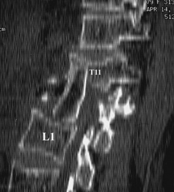
AUTOGRAFT ILIAC CREST
Autograft yields very high rates of fusion, as long as mechanical stability is provided. It shows rapid healing and modulus similar to vertebral body. After fusion has occurred, the construct shows extreme durability (Fig. 37-1). Even though the fusion bed is irradiated, the fusion rate is very good. When survival is expected to be more than 6 months, autograft is the most favored graft material. However, in anterior reconstruction involving at least one vertebral body and its adjacent discs in thoracic and lumbar spine, the size of the defect to be filled necessitates the harvesting of a large amount of autograft, often associated with a significant morbidity at the graft harvesting sites. Furthermore, the mechanical resistance of such a large reconstruction with autograft is usually not sufficient to allow full weight-bearing without external orthosis. Other problems are pseudoarthrosis, necrosis after adjuvant radiation, transplant loosening, and morbidity at the donor site.
VASCULARIZED RIB AUTOGRAFT
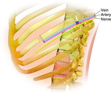
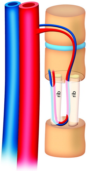
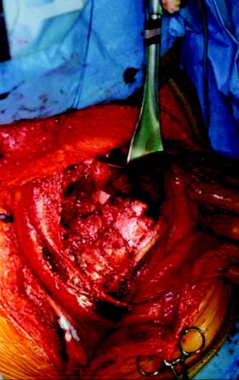
During the thoracic approach, the periosteum of the rib is neither divided nor rasped. Intercostal muscles are divided above and below the selected rib to protect the periosteum and the vessels running below the distal edge of the rib (Fig. 37-2). At the front, vessels are ligated and divided along with the rib. At the back, the periosteum is incised all around the posterior arch of the rib and is rasped with care, pushing away the pedicle in one block. The rib is elevated with its accompanying artery and vein. The intercostal nerve is separated from the vascularized rib. The vascularized rib is isolated. Anteriorly the end is near the costochondral junction, and posteriorly it is near the costal angle. The rib is wrapped up in a wet pad. The mean length of the resected segment is about 10 cm.
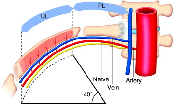
The length of the useful segment can vary according to the number of levels to be fused. In thoracic levels, the length of 10–12 cm can cover four or five segments. The average length of the vascular pedicular segment is 5–6 cm. The useful segment usually has a 40-degree curvature (Fig. 37-3).
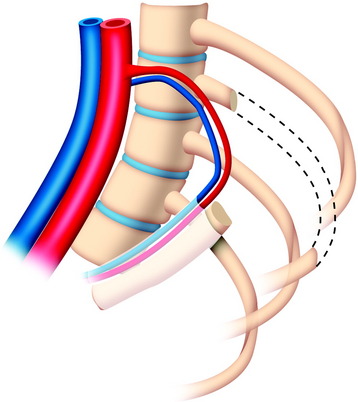
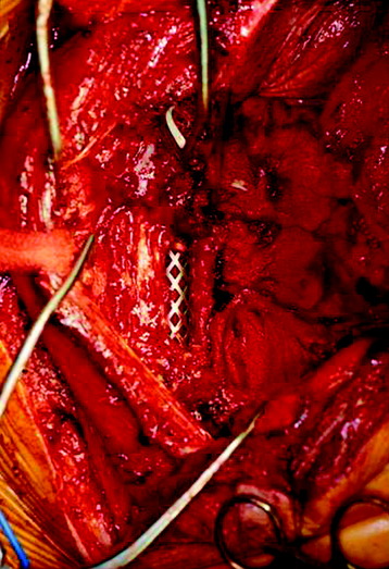
The useful segment of the rib is mobilized around the vascular pedicle. The surgeons must be sure that the pedicle is not twisted, elongated, or tight, and not folded (Fig. 37-4). The whole length of the rib is sectioned into two or three pieces. The length of each fragment adjusts to match the defect in the corpectomy. The rib is folded cautiously to prevent injury to the accompanying vessel (Fig. 37-5). The natural progression of non-vascularized bone graft is a first stage of necrosis, then a second stage of creeping substitution. When the vascularized graft is used, the creeping substitution is avoided, and fusion and bone healing are obtained within 3 months.
TITANIUM MESH CAGE
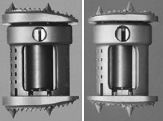
Recent studies on the titanium mesh cage (TMC) have reported excellent stability rates compared with the traditional tricortical iliac crest grafts or fibular grafts because they provide immediate immobilization and a larger healing surface when packed with cancellous bone (Fig. 37-6).2 The mesh cage allows anchoring by bone because its end tip has spikes. Unlike bone grafts, both ends of a titanium mesh cage have sharp edges that allow it to be anchored into the adjacent vertebral bodies, which results in torsional stability (Fig. 37-7). Early stabilization could be achieved by making the cage ends “bite” into the adjacent vertebral bodies.
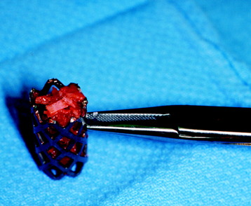
It is postulated that preservation of the endplates may prevent potential telescoping of the graft when placing cages.3 End caps, designed to prevent telescoping, increase the cage’s maximum load-bearing ability but do not affect the construct’s stiffness. They may interfere with the bone-bone interface or the transference of stress lines, which is needed for fusion, through the TMC. The plate/TMC combination results in the strongest, stiffest construct, preventing flexion and extension, rotation, and parallelogram effect. The inability of plain radiography to evaluate bone growth within the TMC can be overcome with computed tomography (CT) scanning. The presence or extent of bone growth within the TMC can be determined from CT scanning. On CT images, hyperdense areas are seen, which suggests bone growth within the TMC, and indirect evidence of fusion is presumed based on radiographically documented stability. The TMC/plate construct has been safe and effective as a vertebral replacement in the spine.
ALLOGRAFT
Allografts include femoral cortical rings, tibial rings, fibular rings, and humeral cortical rings (Figs. 37-8 and 37-9). Some surgeons advocate the use of an allograft-autograft composite by packing the medullary canal of the allograft with autografts. Deep-frozen cortical rings and freeze-dried cortical rings are available. Both deep-frozen and freeze-dried cortical allografts have been strong enough to withstand loads taken by the reconstructed spine. The results of the fusion operation have been good. Infection and implant failure are rare.
Allografts are of multiple sizes and provide reliable fusion with the host bone with partial bone remodeling, preventing fatigue fracture. The major disadvantage is the risk of transmission of the disease. The risk can be reduced with several physical and chemical treatments, including washing, lipid extraction, prion inactivation, freeze drying, packing, and sterilization by 2.5 Gy gamma irradiation.4
Two-dimensional (2D) CT evidence of bony ingrowth into the central canal of a fibula strut allograft provides an adequate means of quantifying the extent of fusion (Fig. 37-10).
CARBON FIBER STACKABLE CAGE
A carbon fiber stackable cage (CFSC) system is presented to promote the reconstruction of the anterior column after vertebrectomy or corpectomy in tumor surgery.5,6
Modularity, immediate stability, early fusion of the graft, radiolucency, and no risk of disease transmission are the main advantages of this system (Fig. 37-11).
A modular prosthesis in carbonium and titanium with pedicles may be connected to the posterior implant (plates and bars) (Fig. 37-12).
Modularity means that surgeons have the ability to intraoperatively reconstruct any loss of spinal substance resulting from unexpected extension of the resection (Fig. 37-13). Radiolucency enables surgeons to recognize whether the bony fusion is successful, and tumor recurrence also can be detected earlier.
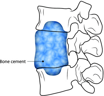
POLYMETHYLMETHACRYLATE RECONSTRUCTION IN METASTATIC TUMOR SURGERY
For the anchorage of the PMMA, several methods are used.
Partial Vertebral Body Defect
For fixation of the bone cement graft, a partial bone defect is created in the endplate of the adjacent vertebral body. The defect site is filled with bone cement to form the anchorage (Fig. 37-14).
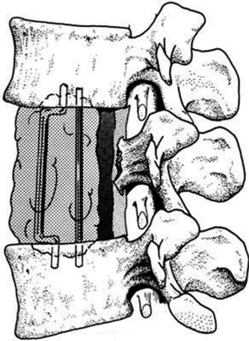
Steinmann Pin–Assisted Polymethylmethacrylate Graft
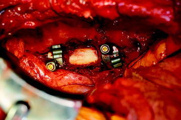
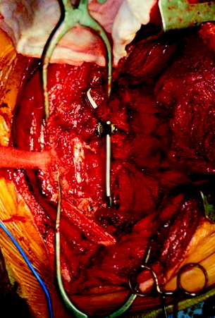
After the corpectomy, Steinmann pins are placed into the vertebral bodies above and below the level of the resection, and PMMA is poured into the resection cavity (Fig. 37-15).7 Two Steinmann pins are cut to appropriate lengths (approximately one full vertebral body height longer than the total vertebrectomy defect) and curved slightly to facilitate placement (Fig. 37-16). The direction of passage will be rostral first, and caudal second. The first pin is passed, with the aid of large needle holders, into the center of the rostral vertebral body through the bony endplate of the disc space. The concave curve is facing away from the vertebral bodies until the other tip is passed into the bottom of the vertebrectomy defect. That caudal tip is then passed through the center of the lower endplate until both rostral and caudal tips are well buried in bone (Fig. 37-17). The second pin is inserted in a similar fashion, next to the first. The placement of two pins allows for stability of the resected segment in translational as well as angular movements. Pins must be carefully placed to prevent injury to the adjacent pleural, neural, and vascular structures.
EXPANDABLE CAGE
Vertebral Body Replacement Cage
The use of cages for spinal surgery is shown to be effective in providing anterior column support and long-term stability. For non-expandable cages, adjusting the cage size to the endplates and height of the corpectomy defect is limited by predefined cage endplate angle and height. Direct correction of internal kyphosis of the anterior column is difficult with currently available non-expandable cages. With expandable cages, these difficulties can be resolved (Fig. 37-18). No biomechanical differences can be observed between the expandable and non-expandable cages. However, the clinical use of these implants as stand-alone cages cannot be advocated.
TECHNIQUE FOR VERTEBRAL BODY REPLACEMENT CAGE
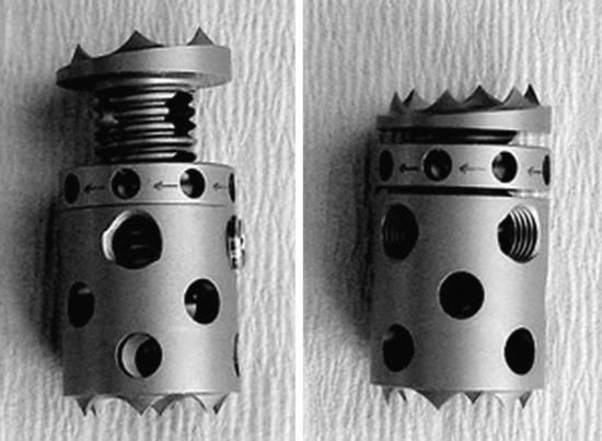
The expandable VBR cage is a commercially available, expandable titanium cage consisting of a round, flat endplate surface with small spikes (Fig. 37-19). Rotational stability is enhanced when the spikes are firmly purchased into the endplates of the corpectomy defect.8 After corpectomy, the appropriate VBR implant size is determined by using a caliper to measure the height and width of the corpectomy defect. Autograft bone from the corpectomy and iliac crest are used to fill the cage. The cage can be expanded with an expansion wrench. Once the cage is distracted to its final length, additional graft material can be added to fill the end pieces completely. As expansion of the cage occurs, increasing stiffness of endplate purchase can be felt and seen.
DISADVANTAGES
These cages are highly versatile and easily expandable and can be used to reconstruct the vertebral column defect and to correct the sagittal alignment of the spine.9,10 They can easily distract across the resected vertebral defect for correction of the deformity, allow immediate load bearing after corpectomy, and provide a satisfying long-term functional result. Very minimal subsidence occurs with expandable cages because of their broader surface and duller edges at each end.
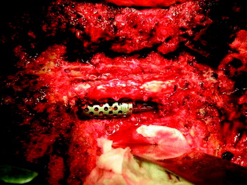
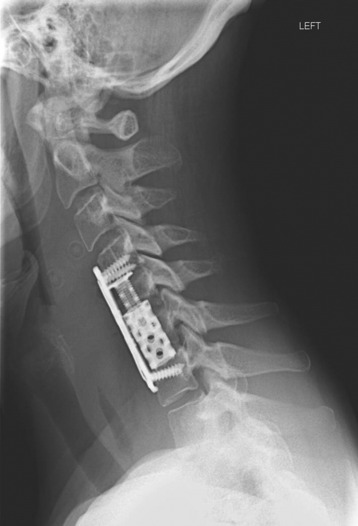
In the cervical area, the VBR cage can be of use with or without plate application in anterior reconstruction. Because the cage is not designed to be a stand-alone device, additional anterior plating is placed in the lower cervical levels (Fig. 37-20). However, in the upper cervical spine, the plating is very difficult. In cases in which anterior plating is not available, the VBR cage is favored because its spine can purchase the endplate firmly, which provides the stronger construct compared with other devices (Fig. 37-21).
BIOMECHANICAL STABILITY AFTER ONE-LEVEL CORPECTOMY
Anterior instrumentation provides less potential stability than do posterior and combined instrumentations in all motion directions.12 Anterior instrumentation, after VBR, shows greater motion than the intact spine, especially in axial torsion. Posterior instrumentation provides greater rigidity than does anterior instrumentation, especially in flexion-extension. The combined instrumentation provides superior rigidity in all directions compared with all other instrumentation. Posterior and combined instrumentations provide greater rigidity than does anterior instrumentation. Anterior instrumentation should not be used alone in vertebral body replacement.
CASE ILLUSTRATION
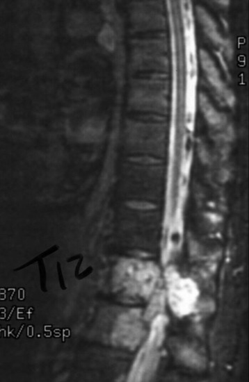
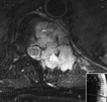
A 45-year-old woman was diagnosed with metastasis of the osteosarcoma spine. Magnetic resonance imaging (MRI) showed that tumors had infiltrated the vertebral bodies (T9, T10), left-side pedicle, lamina, and facet joint, which means three-column involvement (Figs. 37-23 and 37-24).
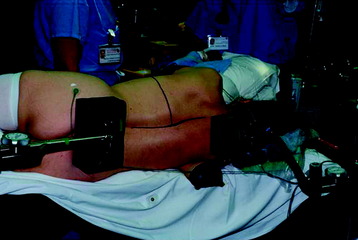
The patient was placed into the left lateral decubitus position. A T-shaped skin incision was made with the horizontal line corresponding to T9 vertebral body level (Fig. 37-25).
Superior and inferior flaps were elevated with the superior myocutaneous flap including the trapezius muscle (Fig. 37-26). The horizontal incision was extended superiorly and inferiorly along the spinous processes. The trapezius and latissimus dorsi muscles were mobilized laterally and detached from their origins on the spinous processes. The paraspinal muscles were transected above and below the level of tumor involvement and stripped off the spinous process.
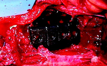
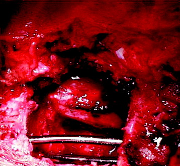
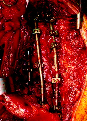
The thoracic cavity was entered through the posterolateral route. The 8th, 9th, 10th, and 11th ribs were removed from the rib heads to the proximal segments (Fig. 37-27). (If possible, the extrapleural approach is favored because the parietal pleura is not open. When the transpleural route is used, the lung is then retracted anteriorly and inferiorly.) The parietal pleura overlying the spine was incised to adequately expose the segmental vessels for ligation. The azygos vein was ligated proximally and distally and was removed with the specimen. The anterior spinal column between T8 and T11 was exposed. The aorta and esophagus were mobilized away from the anterior longitudinal ligament. The bridging veins connecting the hemiazygos system to the azygos vein were ligated on the left side of the spinal column. A complete laminectomy of T9 and T10 was performed with left-side facetectomy. The nerve roots on the right side (T9, T10) were cut and retracted to the left, and the dura was separated from the posterior longitudinal ligament. T9, T10 corpectomies were performed via the transpedicular route. The inferior endplate of T8 and the superior endplate of T11 were removed, and a TMC filled with autograft rib, allograft corticocancellous bone, and demineralized bone matrix was properly positioned and secured between the vertebral bodies of T8 and T11. An appropriate-length rod was selected and secured to the screws within the anterior vertebral bodies (Fig. 37-28).
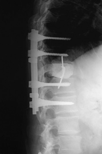
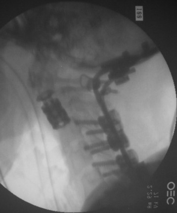
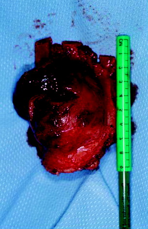
Posterior stabilization was performed with a hook and rod system, and the left-side posterior rod was connected to the anterior rod with a transverse connector (Fig. 37-29). Gross total removal was attempted with a wide resection margin. The removed tumor mass is seen with a measuring device (Fig. 37-30).
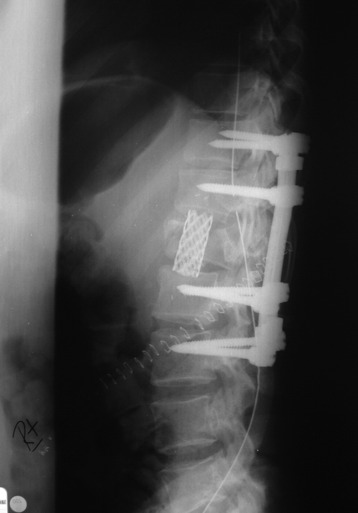
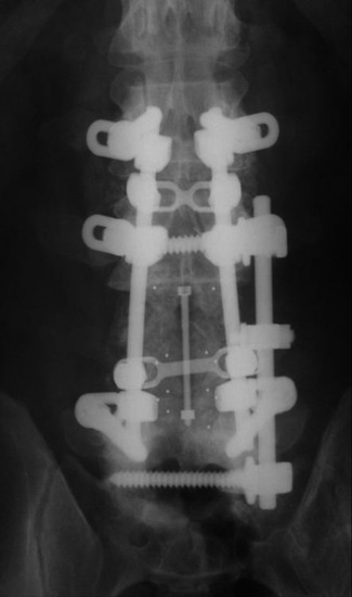
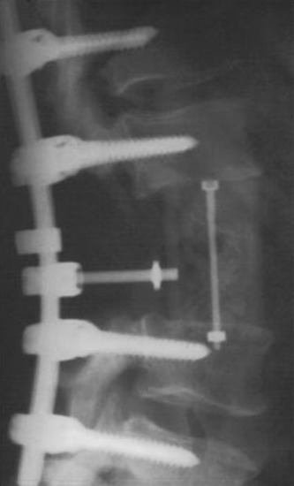
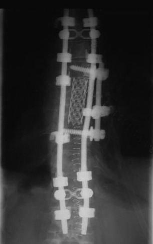
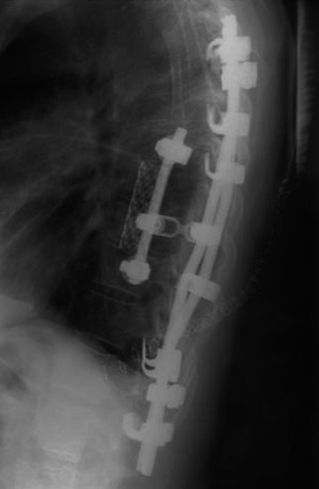
Postoperative x-ray showed that combined stabilization was accomplished after complete removal of T9, T10 vertebral bodies and left-side posterior arch (Figs. 37-31 and 37-32).
[/level-membership-for-neurosurgery-category][not-level-membership-for-neurosurgery-category]
Chapter 37 Vertebral Body Reconstruction in the Thoracic Spine
GOALS OF CORPECTOMY RECONSTRUCTION
The purpose of vertebral body reconstruction is to restore anterior and middle column weight-bearing function and to obtain the intended bony fusion.1 Solid body fusion appears to be the most reliable means to achieve this goal, but fibrous union also may provide a long-term favorable clinical outcome. Several instrumentation options can be used depending on the extent of the vertebral body resection.
RECONSTRUCTION OPTIONS
AUTOGRAFT ILIAC CREST
Autograft yields very high rates of fusion, as long as mechanical stability is provided. It shows rapid healing and modulus similar to vertebral body. After fusion has occurred, the construct shows extreme durability (Fig. 37-1). Even though the fusion bed is irradiated, the fusion rate is very good. When survival is expected to be more than 6 months, autograft is the most favored graft material. However, in anterior reconstruction involving at least one vertebral body and its adjacent discs in thoracic and lumbar spine, the size of the defect to be filled necessitates the harvesting of a large amount of autograft, often associated with a significant morbidity at the graft harvesting sites. Furthermore, the mechanical resistance of such a large reconstruction with autograft is usually not sufficient to allow full weight-bearing without external orthosis. Other problems are pseudoarthrosis, necrosis after adjuvant radiation, transplant loosening, and morbidity at the donor site.
VASCULARIZED RIB AUTOGRAFT
During the thoracic approach, the periosteum of the rib is neither divided nor rasped. Intercostal muscles are divided above and below the selected rib to protect the periosteum and the vessels running below the distal edge of the rib (Fig. 37-2). At the front, vessels are ligated and divided along with the rib. At the back, the periosteum is incised all around the posterior arch of the rib and is rasped with care, pushing away the pedicle in one block. The rib is elevated with its accompanying artery and vein. The intercostal nerve is separated from the vascularized rib. The vascularized rib is isolated. Anteriorly the end is near the costochondral junction, and posteriorly it is near the costal angle. The rib is wrapped up in a wet pad. The mean length of the resected segment is about 10 cm.
The length of the useful segment can vary according to the number of levels to be fused. In thoracic levels, the length of 10–12 cm can cover four or five segments. The average length of the vascular pedicular segment is 5–6 cm. The useful segment usually has a 40-degree curvature (Fig. 37-3).
The useful segment of the rib is mobilized around the vascular pedicle. The surgeons must be sure that the pedicle is not twisted, elongated, or tight, and not folded (Fig. 37-4). The whole length of the rib is sectioned into two or three pieces. The length of each fragment adjusts to match the defect in the corpectomy. The rib is folded cautiously to prevent injury to the accompanying vessel (Fig. 37-5). The natural progression of non-vascularized bone graft is a first stage of necrosis, then a second stage of creeping substitution. When the vascularized graft is used, the creeping substitution is avoided, and fusion and bone healing are obtained within 3 months.
TITANIUM MESH CAGE
Recent studies on the titanium mesh cage (TMC) have reported excellent stability rates compared with the traditional tricortical iliac crest grafts or fibular grafts because they provide immediate immobilization and a larger healing surface when packed with cancellous bone (Fig. 37-6).2 The mesh cage allows anchoring by bone because its end tip has spikes. Unlike bone grafts, both ends of a titanium mesh cage have sharp edges that allow it to be anchored into the adjacent vertebral bodies, which results in torsional stability (Fig. 37-7). Early stabilization could be achieved by making the cage ends “bite” into the adjacent vertebral bodies.
It is postulated that preservation of the endplates may prevent potential telescoping of the graft when placing cages.3 End caps, designed to prevent telescoping, increase the cage’s maximum load-bearing ability but do not affect the construct’s stiffness. They may interfere with the bone-bone interface or the transference of stress lines, which is needed for fusion, through the TMC. The plate/TMC combination results in the strongest, stiffest construct, preventing flexion and extension, rotation, and parallelogram effect. The inability of plain radiography to evaluate bone growth within the TMC can be overcome with computed tomography (CT) scanning. The presence or extent of bone growth within the TMC can be determined from CT scanning. On CT images, hyperdense areas are seen, which suggests bone growth within the TMC, and indirect evidence of fusion is presumed based on radiographically documented stability. The TMC/plate construct has been safe and effective as a vertebral replacement in the spine.
ALLOGRAFT
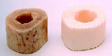
Allografts include femoral cortical rings, tibial rings, fibular rings, and humeral cortical rings (Figs. 37-8 and 37-9). Some surgeons advocate the use of an allograft-autograft composite by packing the medullary canal of the allograft with autografts. Deep-frozen cortical rings and freeze-dried cortical rings are available. Both deep-frozen and freeze-dried cortical allografts have been strong enough to withstand loads taken by the reconstructed spine. The results of the fusion operation have been good. Infection and implant failure are rare.
Allografts are of multiple sizes and provide reliable fusion with the host bone with partial bone remodeling, preventing fatigue fracture. The major disadvantage is the risk of transmission of the disease. The risk can be reduced with several physical and chemical treatments, including washing, lipid extraction, prion inactivation, freeze drying, packing, and sterilization by 2.5 Gy gamma irradiation.4
Two-dimensional (2D) CT evidence of bony ingrowth into the central canal of a fibula strut allograft provides an adequate means of quantifying the extent of fusion (Fig. 37-10).
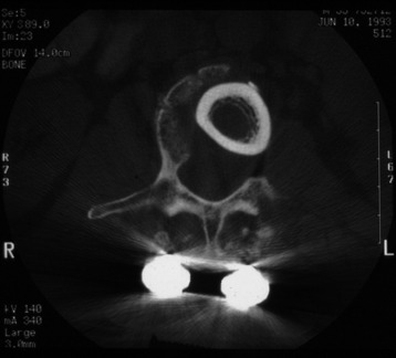
Fig. 37-10 Femoral ring allograft provides a strong cortical construct with a large contact surface.
[/not-level-membership-for-neurosurgery-category]
