Chapter 144 Ventral Subaxial Cervical Fixation Techniques
Cervical Spine Anatomy
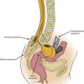
The cervical spine can be subdivided into two regions: the upper (C1 and C2) and the lower (C3-7) cervical regions. The normal cervical spine is lordotic in alignment. The upper cervical spine is unique because of its distinct anatomic arrangements, compared with the rest of the cervical spine. C1 has no centrum, and as such, is a bony ring that allows for the intrusion of the dens of C2 between the lateral masses of C1. The dens articulates with the dorsal aspect of the ventral portion of the ring of C1. The lateral masses of C1 join with the occipital condyles and C2 by kidney-shaped articulations. The C2 vertebra has many attributes of the more caudal cervical vertebra. It also has a rostral extension known as the dens or odontoid process. The pars interarticularis is substantial and projects from the lamina to attach to the lateral mass. The atlanto-occipital joint allows flexion-extension (25 degrees), as well as a minimal degree of lateral flexion (5 degrees) and minimal rotation (5 degrees). The atlantoaxial joint allows 20 degrees of flexion-extension, 5 degrees of lateral bending, and 40 degrees of axial rotation.1–3 The failure strength of the alar ligament is about 200 N, whereas that of the transverse ligament is 350 N.4 The vertebrae of the middle and lower cervical spine are relatively uniform. A unique characteristic of this region is its lordotic alignment, which may aid in spinal cord injury prevention because most axial loads are imparted symmetrically to the spine rather than with a significant flexion component. Because the addition of a flexion component to an axial load greatly increases the chance of vertebral body failure and the retropulsion of bone and disc fragments into the spinal canal, the lordotic posture thereby helps to prevent catastrophic injury.
Ventral Instrumentation
Only relatively recently have ventral instrumentation constructs been applied to the cervical region. These constructs are used to treat a variety of abnormalities of the subaxial cervical spine, including degenerative, neoplastic, and infectious processes, and trauma-related injuries. These techniques involve cervical plating systems that are applied to the ventral cervical spine to promote fusion and to maintain graft position and spinal alignment. Caspar developed a semiconstrained (semirigid or dynamic) plate system that uses a bicortical screw purchase in the vertebral body.5 Johnson et al. subsequently developed a rigid or constrained plate system that uses a screw-plate locking mechanism without bicortical purchase.6 Several commercial ventral fixation systems are available, but prior to the placement of a single implant, a surgeon should ask these questions: Is a spinal implant indicated? Is a rigid or dynamic implant optimal? Is deformity reduction, correction, or prevention required? Which system is ideal for obtaining fusion and preventing subsidence? These questions are key and require a sound understanding of biomechanical principles as they apply to the cervical spine.
Biomechanics of Ventral Subaxial Spine Constructs
Ventral Compression (Tension Band) Fixation
Unlike ventral distraction techniques, ventral compression techniques do not employ interbody struts that apply compression forces to the spine. In general, it is difficult to use rods to provide significant compression or distraction in the ventral cervical spine as can be easily achieved in the thoracic and lumbar spine. However, with the development of implants such as the DOC VCSS (DePuy Spine, Raynham, MA; discussed later in this chapter), such use has been facilitated. This device allows the application of compression using a cantilevered screw-rod system, thereby enabling preloading of the bone graft and thus increasing bone healing.
Multilevel Fixation
Multisegmental fixation is not used as extensively in the ventral as in the dorsal spine. Reasons include the often inadequate ventral longitudinal exposure and the relatively weak implant-vertebral body interface. The weak implant-vertebral body interface results from the fact that the vertebral body is primarily composed of cancellous bone. The utilization of bicortical screw purchase has been developed as a strategy to overcome this problem, but it is not without risk. Other problems encountered with multilevel constructs include subsidence—the process by which the interbody graft settles in the spine. This can be avoided when “good carpentry” techniques are employed in the preparation of the end plates and the interbody or strut graft. As previously discussed, a variety of commercial ventral plates are available on the market. These are usually classified as rigid or dynamic plates. It has been observed that dynamic plates load share more than rigid plates, thereby preventing the graft from absorbing most of the load applied to the spine.7 With multilevel constructs, the caudal end of the construct is the most likely region to fail as a result of screw loosening or hardware failure, because there is a longer moment arm and increased forces at the caudal end of the construct.8 The incidence of increased failure at the caudal end of a multilevel construct can be decreased by following a few key principles: (1) maximizing screw purchase at the caudal end of the construct, (2) using dynamic fixation, (3) using meticulous bone-grafting techniques, and (4) limiting postoperative spine motion with a rigid collar in the first few months after surgery.
First-Generation Plates
Caspar Plate System
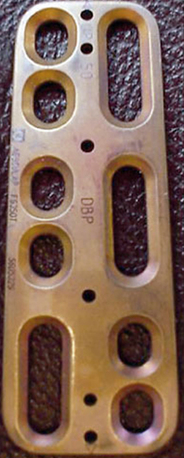
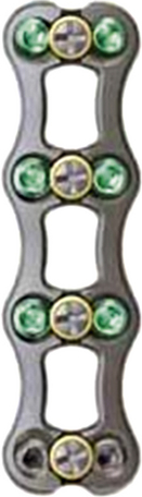
This titanium plate is nonconstrained, meaning that the screws are not locked to the plate (Fig. 144-1). The set comes with both unicortical and bicortical screws. The unicortical screws come in a variety of lengths from 10 to 28 mm. Screws have a constant outer diameter of 3.5 mm and an inner diameter of 2.2 mm. The bicortical screws are self-tapping and come in lengths from 14 to 19 mm. The outer diameter is 4 mm, and the inner diameter is 2.2 mm at the tip and 2.7 mm at the head. The screws are made of a titanium alloy with a corundum-blasted surface over a third of the length at the tip.
Techniques for Placing Caspar Ventral Cervical Plates
Prior to plate placement, distracting pins are placed in both the rostral and caudal vertebral bodies. The distracting pins are placed using a mallet and a screwdriver. The length of the plate to be used may be determined by reviewing preoperative imaging, which can be reconfirmed intraoperatively. It is important to place the plate in a manner that avoids the screw holes being placed in soft tissue or in the holes caused by the distracting pins. No screws should be placed within 2 mm of the vertebral end plates. The plate should be placed in the midline and should fit flush with the vertebral bodies. If the plate fits poorly, ventral osteophytes should be drilled off in order to ensure an adequate fit. If the curvature of the cervical spine does not allow for an adequate fit, the plate may be bent as a last resort. It is important to avoid multiple bends as this may weaken the plate. Next, the distance from the anterior to the posterior marginal line of the vertebral body is determined from the preoperative imaging, and the drill guide is set to 3 mm less than this distance. The plate is held in place with a temporary fixation pin or a plate holder. Next, the drill guide is placed into the screw holes, and the drill is used to drill the vertebral body to the preset length. Next, the screw holes are tapped and the first screw is placed. It is not fully tightened, and the rest of the screws are placed in a diagonal fashion.
Second-Generation Plates
The second-generation plates were rigid implants and have the benefits of providing rigid stabilization, maintenance of alignment, reduced need for postoperative immobilization, earlier return to function, and potentially enhanced fusion rates.9 These implants were described as restricted and constrained. Their disadvantage is that they may stress shield the bone graft and result in nonunion or implant failure. Stress shielding, as the term implies, occurs when the implant reduces fusion-promoting stresses on the bone graft, thereby leading to a nonunion.
Cervical Spine Locking Plate
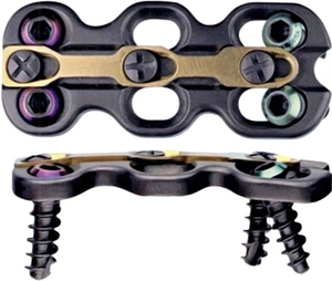
The Synthes Cervical Spine Locking Plate (Synthes CSLP, West Chester, PA) was developed and designed as a prelordosed plate. The bushings in plate holes allow for screw angulation and locking and come with a wide variety of screws, including self-drilling and self-tapping, as well as unicortical and bicortical screws. The screws vary in length from 12 to 20 mm (Fig. 144-2).
Orion Anterior Cervical Plate System
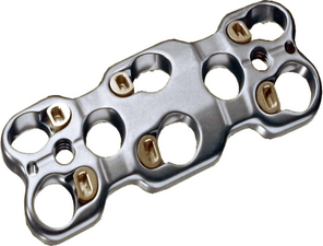
The Orion plate (Medtronic, Sofamor-Danek, Memphis, TN) is highly constrained, and the screws are locked into the plate at a fixed angle. The Orion plate has a predetermined lordotic curvature. The fact that the cephalad and caudad screws are locked in place prevents screw migration if the screws break. The plate design also allows for convergent screw placement, thereby reducing the risk of injury to the vertebral artery. The superior screws are directed 15 degrees cephalad and 6 degrees medially, and the inferior screws are placed 15 degrees caudally and 6 degrees medially. Variable-length 4-mm cancellous screws are available ranging from 10 to 26 mm. The plates vary in size from 25 to 90 mm. The Orion plate is made of a titanium alloy with a titanium-anodized (Tiodized) surface coating, which increases the surface’s resistance to wear and improves the fatigue life (Fig. 144-3).
Third-Generation Plates
Due to the problem of stress shielding encountered in the second-generation plates, the dynamic plates were again revisited. This improvement in the first-generation plates led to the development of a third generation of plates that improved on the original Caspar plate design by preventing screw backout while allowing for some movement at the screw-plate interface, thereby enabling load sharing between the bone graft and the implant. These third-generation plates were described as dynamic plates. There are two subsets of dynamic plates: (1) rotational and (2) translational. The rotational dynamic plates allow screws to rotate or toggle at the screw-plate interface and include the Atlantis (Medtronic, Sofamor-Danek), Blackstone (Blackstone Medical, Inc., Springfield, MA), Aline (Surgical Dynamics, Inc., Norwalk, CT) Zephir (Medtronic, Sofamor-Danek), Slim-Loc (DePuy Spine, Raynham, MA) Acufix (Austin, TX) and Deltaloc (Alphatec Spine, Carlsbad, CA) plates. Translational dynamic plates allow for axial translation and rotation of the plate and include the Premier (Medtronic, Sofamor-Danek) ABC (Aesulap, Tuttlingen, Germany) and DOC (DePuy Spine) plates. Movement at the screw-plate interface was planned to avoid stress shielding so that, theoretically, fusion rates would increase and time to fusion would diminish.
Atlantis Anterior Cervical Fixation System
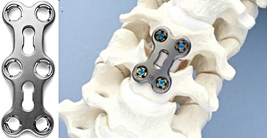
The Atlantis cervical plate (Medtronic, Sofamor-Danek, Memphis, TN) is made of titanium and has an integral locking mechanism that helps to reduce screw pull-out. The Atlantis plate was designed with the concepts of load sharing and load bearing in mind. The versatility of this plating system allows for different levels of fixation rigidity achieved by the design of the two types of fixation screws in the system. An Atlantis plate that is secured with fixed-angle screws is a relatively rigid load-bearing construct and is defined as a constrained construct with maximum stability at the graft site. The variable-angle screws, when used with the Atlantis plate, allows for transfer of axial load forces to the graft. Finally, a hybrid construct can be created by using fixed-angle screws at one end of the plate and variable-angle screws at the other end. This creates a semiconstrained construct that provides a moderate degree of fixation rigidity while allowing for some transfer of axial loading to the bone graft. The plates vary in size from 19 to 110 mm (Fig. 144-4).
Premier Anterior Cervical Plate
The Premier is a dynamic plate designed by Medtronic that permits axial load sharing via translational movement of the screws at all levels except the most caudal end. The Premier plating system has screws that are either 4.0 mm or 4.5 mm in diameter. The 4-mm screws vary in length from 10 to 20 mm. The 4.5-mm screws come in 13-, 15-, and 17-mm sizes. The plate has fixed holes and slots, which can accept either diameter of screw. The caveat is that the 4.5-mm-diameter screws have less angle variability when placed in the slots. The plate comes in 32 different sizes, ranging from 23 to 110 mm (Fig. 144-5).
SLIM-LOC Anterior Cervical System
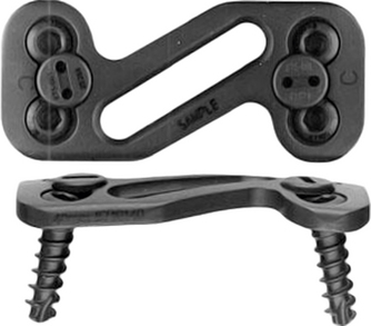
In 2002, DePuy Spine released the semiconstrained SLIM-LOC anterior cervical plate. The template for this new plate was the original Codman plate. The changes to the Codman plate that resulted in the development of the SLIM-LOC plate included reducing the plate’s thickness to 2.1 mm and increasing the plate-screw bending rigidity by 40%. This was achieved by increasing the inner diameter of the screw in the direction of the screw head. The SLIM-LOC plate is a dynamic system that prevents screw backout using the cam-lock mechanism. The SLIM-LOC plate has a precontoured curvature, which is appropriate for the majority of cases. There is also a plate bender in the set if further curvature is required (Fig. 144-6).
Overall, the rationale behind using anterior cervical plates is that it helps maintain the bone graft in place, and it promotes fusion by providing stability between the bone graft and the adjacent vertebrae. It also helps maintain proper cervical alignment. The use of cervical plates has also allowed surgeons to more liberally use allograft since allograft success rates have been shown to equal those of autograft when ventral plating is used.10
General Guidelines for Plate Placement
Plate length is usually selected by visual inspection in the field and measurement on preoperative imaging. The plate should be long enough to extend beyond the graft-body junction both rostrally and caudally to avoid placing the plate screws into the graft. It is also important to ensure that the plate is placed at least 5 mm from the adjacent disc spaces that are not being fused in order to decrease the incidence of adjacent level ossification disease (ALOD) as reported by Riew et al.11 ALOD is described as osteophyte formation and periplate ossification of the adjacent segments. The ventral vertebral bodies may need to have osteophytes drilled off in order to allow the plate to sit flush on the ventral aspect of the vertebral bodies. The plate should also be placed in the midline in order to prevent contact between the plate and vital structures such as the esophagus. If bicortical purchase is required, the dorsoventral vertebral body length should be measured on preoperative imaging and should be checked again in situ after the discectomy has been performed.
Multilevel Anterior Cervical Discectomy and Fusion versus Corpectomy
A single-level anterior cervical discectomy and fusion (ACDF) with a plate is a very successful procedure, but as the number of levels increase, the fusion rates drop compared with those for a single-level operation. Wang et al. have postulated that a single-level corpectomy and strut graft may produce better fusion than two-level adjacent discectomies with multiple grafts.12
Bone Graft Options in Ventral Subaxial Cervical Fixation
BAK/C Interbody Fusion System
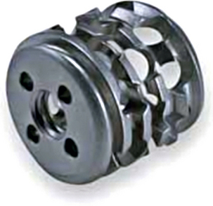
The BAK/C interbody system (Zimmer Spine, Minneapolis, MN) provides an alternative to either a tricortical structural autograft, which is associated with donor site morbidity, or allograft, which may be associated with a very small risk of disease transmission. The BAK/C is a threaded hollow device that is made of a titanium alloy (Ti-6Al-4V) and as such cannot collapse and is highly resistant to migration. It has a porous design, which allows bone growth through all sides. In comparison to anterior cervical plates, the BAK/C has a zero profile, and if adjacent segments need to be fused, it does not have to be removed. The device comes in five diameters (6, 7, 8, 10, and 12 mm) without factoring in the threads. The threads add an additional 2.5 mm to the outer diameter of the device. The BAK/C device allows for both unilateral and bilateral placement. It is important to note that the best fusion results are obtained when the BAK/C is packed with local bone graft and bone graft extenders (Fig. 144-7). Cauthen et al. described a 97% fusion rate with stand-alone BAK/C. Their study compared fusion rates between stand-alone BAK/C, ACDF without a plate, and ACDF with a plate.13
Bengal Carbon Fiber Interbody Cage
The Bengal (DePuy Spine, Raynham, MA) cervical cages are carbon fiber polymer cages that bear the mechanical forces of the spine to promote fusion. The modulus of elasticity of these carbon fiber cages is similar to that of cortical bone. This may help improve load sharing through the graft. The cages should be filled with cancellous autograft, which does not require as extensive a harvesting process as tricortical graft. As a result of the makeup of the interbody cage, it is not susceptible to collapse and the inherent height results in indirect neuroforaminal decompression. The carbon fiber cages come in three sizes: standard (12 mm × 14.5 mm), large (14 mm × 17 mm), and extra large (16 mm × 20 mm) (Fig. 144-8).
Polyetheretherketone Spacer
Polyetheretherketone (PEEK) is a polymer with a modulus of elasticity within the range for cancellous bone. The modulus of elasticity is defined as stress divided by strain. The modulus of elasticity of cancellous bone ranges from 0.5 to 5, and the modulus of elasticity of PEEK is 3.7. These PEEK implants do not produce artifacts on plain films, CT, or MRI. The implant is identified on plain radiographs by a titanium wire that is inserted into the wall of the PEEK spacer. PEEK elicits a minimal inflammatory response and has excellent resistance to corrosion. PEEK is insoluble in most solvents and has long-term biocompatibility.14,15 The use of PEEK spacers reduces graft subsidence that may be seen with titanium cages, and, as such, PEEK cages are a reasonable alternative to allograft for ACDF.16 The center of the spacer may be filled with local autograft or other bone graft extenders with osteoinductive properties.
Dvorak J., Schneider E., Saldinger P., et al. Biomechanics of the craniocervical region: the alar and transverse ligaments. J Orthop Res. 1988;6:452-461.
Johnsson H., Cesarini K., Petren-Mallmin M., et al. Locking screw-plate fixation of cervical fractures with and without ancillary posterior plating. Arch Orthop Trauma Surg. 1991;111:1-12.
Panjabi M., Dvorak J., Duranceau J., et al. Three dimensional movements of the upper cervical spine. Spine (Phila Pa 1976). 1988;13:726-730.
Panjabi M.M., Isomi T., Wand J. Loosening of the screw-vertebra junction in multilevel anterior cervical plate constructs. Spine (Phila Pa 1976). 1999;24:2383-2388.
Tippets R.H., Apfelbaum R.I. Anterior cervical fusion with Caspar instrumentation system. Neurosurgery. 1988;22:1008-1013.
Wang J.C., McDonough P.W., Endow K.K., Delamarter R.B. A comparison of fusion rates between single-level cervical corpectomy and two-level discectomy and fusion. J Spinal Disord. 2001;14(3):222-225.
White A.A., Panjabi M.M. Clinical biomechanics of the spine, ed 2. Philadelphia: Lippincott; 1990. pp 1–125
1. Panjabi M., Dvorak J., Duranceau J., et al. Three dimensional movements of the upper cervical spine. Spine (Phila Pa 1976). 1988;13:726-730.
2. Penning L., Wilmink J.T. Rotation of the cervical spine: a CT study in normal subjects. Spine (Phila Pa 1976). 1987;12:732-738.
3. White A.A., Panjabi M.M. Clinical biomechanics of the spine, ed 2. Philadelphia: Lippincott; 1990. pp 1–125
4. Dvorak J., Schneider E., Saldinger P., Rahn B. Biomechanics of the craniocervical region: the alar and transverse ligaments. J Orthop Res. 1988;6:452-461.
5. Caspar W., Barbier D.D., Klara P.M. Anterior cervical fusion and Caspar plate stabilization for cervical trauma. Neurosurgery. 1989;25:491-502.
6. Johnsson H., Cesarini K., Petren-Mallmin M., Rauschning W. Locking screw-plate fixation of cervical fractures with and without ancillary posterior plating. Arch Orthop Trauma Surg. 1991;111:1-12.
7. Brodke D.S., Gollogly S., Mohr A., et al. Dynamic cervical plates biomechanical evaluation of load sharing and stiffness. Spine (Phila Pa 1976). 2001;26(12):1324-1329.
8. Panjabi M.M., Isomi T., Wand J. Loosening of the screw-vertebra junction in multilevel anterior cervical plate constructs. Spine (Phila Pa 1976). 1999;24:2383-2388.
9. Abraham D.J., Herkowitz H.N. Indications and trends in use in cervical spine fusions. Orthop Clin North Am. 1998;29:731-744.
10. Tippets R.H., Apfelbaum R.I. Anterior cervical fusion with Caspar instrumentation system. Neurosurgery. 1988;22:1008-1013.
11. Riew D.K., Park J.B., Cho Y.S. Adjacent level ossification disease (ALOD) secondary to anterior cervical plates. Proceedings of NASS 18th Annual Meeting/Spine J. 2003;3:92S.
12. Wang J.C., McDonough P.W., Endow K.K., Delamarter R.B. A comparison of fusion rates between single-level cervical corpectomy and two-level discectomy and fusion. J Spinal Disord. 2001;14(3):222-225.
13. Cauthen J.C., Theis R.P., Allen A.T. Anterior cervical fusion: a comparison of cage, dowel and dowel-plate constructs. Spine J. 2003;3(2):106-117.
14. Katzer A., Marquardt H., Westendorf J. Polyetheretherketone: cytotoxicity and mutagenicity in vitro. Biomaterials. 2002;23:1749-1759.
15. Moore R., Beredjiklian P., Rhoad R. A comparison of the inflammatory potential of particulates derived from two composite materials. J Biomed Mater Res. 1997;34:137-147.
16. Matge G. Cervical cage fusion with five different implants: 250 cases. Acta Neurochir (Wien). 2002;144:539-549.