[level-membership-for-neurosurgery-category]
Chapter 146 Ventral and Lateral Thoracic and Lumbar Fixation Techniques
Surgery on the ventral thoracic and lumbar spine began nearly 100 years ago. Ventral approaches for decompression of spinal pathology were first attempted in the early 1900s. Pioneers such as Royle1 excised hemivertebrae for the treatment of scoliosis. Ito2 as well as Hodgson and Stock3 refined the ventral (transperitoneal) approach to the thoracolumbar spine for the treatment of Pott disease. These early efforts to decompress ventral spinal pathology were frequently complicated by postoperative mechanical instability and progressive deformity.
The first reports of ventral instrumentation of the spine were from Humphries,4 who developed ventral interbody fusion with ventral plates and unicortical screws. These devices provided little biomechanical advantage. Most of these cases were transperitoneal approaches for debridement and stabilization in patients with Pott disease. The transperitoneal approach was eventually replaced by the retroperitoneal or extracavitary approaches for lesions of the lower thoracic and lumbar spine.
Throughout the 1970s, the preferred treatment for traumatic injuries was dorsal fusion and instrumentation, combined with ventral decompression and fusion. The Dwyer5–7 and Zielke8 devices were developed as ventrolateral implants that could augment or replace dorsal instrumentation. These consisted of screws that traversed the vertebral body that were interconnected with cable (Dwyer) or threaded rods (Zielke) that could be tightened in tension. These devices had limited ability to fixate two-column traumatic injuries. The Dunn device (developed in the late 1970s) represented a more rigid instrument for use in burst fractures. This double-screw, double-threaded rod device provided excellent strength but was removed from the market in 1986 after reports of great vessel erosion and rupture.9
Biomechanical Considerations
Certain biomechanical characteristics of implant systems are important to understand. Rigid implants (e.g., Z-plate, Kaneda systems, Expedium Anterior system, and M-8 dual-rod system) theoretically allow for greater immobilization of the spine. If the implant bears most of the stress, there is a risk of implant breakage or failure. Some plate systems have set screw holes rather than slots, thereby creating a static (nondynamic) condition beginning at the time of plate fixation. Also, stress shielding provided by the rigid fixation may prevent the beneficial compressive forces from enhancing bone fusion (Wolff’s law). Because bone is a biologic, deformable material, repeated stress loading may cause bony erosion and failure at the metallic implant-bone interface.
Indications for Ventrolateral Instrumentation
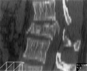
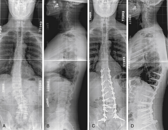
Anterior and middle column trauma (with preservation of the dorsal elements) may be treated adequately with a ventral approach (Fig. 146-1). Failure to recognize significant posterior column injury may result in delayed kyphotic deformity and neurologic deterioration. There are few clinical outcome data to encourage ventral decompression of trauma patients with complete neurologic loss below the level of the lesion. Ventral approaches, however, may be useful in paraplegic patients with a severe kyphotic deformity. Anterior reconstruction may provide better sagittal balance that could be important for long-term pulmonary function, independent transferring, and upper extremity function.
Inadequate radiographic studies before surgery can lead to intraoperative or postoperative complications. Plain radiographs are essential and should include flexion and extension views when there is any suspicion of mechanical instability. In addition, attention should be paid to the density of bone as well as the sagittal and coronal alignment. Patients with scoliosis should have complete 36-inch standing films to assess overall spinal balance. The value of sagittal reconstruction of CT images is often overlooked, particularly after myelographic dye injection. Axial CT may be preferable over MRI to determine the amount of bony spinal canal compromise in trauma. Sagittal MRI often provides excellent views of the PLL. If intact, one may consider use of ligamentotaxis to reduce a burst fracture fragment. MRI has the added advantage of showing signs of soft dorsal tissue injury and hematoma that would commonly go unrecognized with plain radiographs and CT scan alone. Although cost-effectiveness is a primary concern, any patient with complex spinal pathology (and for whom aggressive surgery is contemplated) may require both CT and MRI as part of the workup.
Ventral Surgical Techniques
Positioning
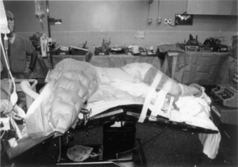
Complications arising from the lateral decubitus position can also be averted with due diligence. We have all placed patients on a bean bag, but the bag must not extend into the axilla of the down arm. A roll (a liter bag of IV solution wrapped in a towel suffices) is placed above the edge of the bean bag just below the axilla. The peroneal nerve in the down leg must be protected with foam and/or gel padding over the fibular head. A pillow is placed between the legs, which are flexed 45 degrees at the hip and knees. The coronal plane of the patient’s thorax must be perpendicular to the floor. Wide tape should be used to secure this position to allow rotation of the bed along its long axis (“airplaning”). Establishing this position assists the surgeon in remaining oriented throughout the procedure, especially during the critical steps of decompressing the spinal cord or placing a vertebral body screw. Some tables are equipped with a compass so that the desired neutral position can be recorded and reset by the anesthesiologist if an “airplane” maneuver is necessary. The perpendicular orientation of the coronal patient plane relative to the floor also allows for more efficient manual reduction of a kyphotic deformity by pressing on the back. The authors routinely “break” or flex the table at the level of the pathology to help open the disc spaces laterally and aid in the insertion of the bone graft (Fig. 146-2). Flexing the table also helps open the space between the 12th rib and the iliac crest. Once the bone graft is in place, the anesthesiologist is asked to return the table to the neutral, unflexed position.
We routinely administer suitable gram-positive antibiotic coverage (e.g., cefazolin 1 g or nafcillin 1 g). In cases of traumatic cord contusion or cord compression caused by tumor, we consider the use of methylprednisolone at least 1 hour before surgery. Using the spinal cord contusion protocol, the patient may receive a bolus of 30 mg/kg over 45 minutes followed by continuous infusion of 5.4 mg/kg per hour for 23 hours.10,11
Paralytic agents are not used after induction to allow for motor response in the event of inadvertent nerve or spinal cord stimulation. The role of somatosensory-evoked potential (SSEP) monitoring is debatable. A decrease in SSEP amplitude of more than 50% and limited or absent intraoperative recovery of amplitude are predictors of a postoperative neurologic deficit.12,13 Despite this reasonable sensitivity and low-false negative rate, SSEP monitoring measures only dorsal column function. False positives are common and often related to anesthetic considerations that can lead to a dangerous desensitization of the surgeon to warnings of intraoperative injury. SSEPs may be useful in deformity cases in which distractive or compressive forces are anticipated and could be reversed.
Motor-evoked potentials may be more accurate than SSEPs in monitoring spinal cord motor function during surgery.14 This technique is extremely sensitive to anesthetics and requires expertise on the part of the anesthesiologist and monitoring team.
Approach and Exposure
Upper Thoracic Spine
Ventral exposure of the rostral levels of the thoracic spine is challenging. The first and second thoracic vertebrae usually can be approached ventrally with a low diagonal or transverse cervical incision. A vertical split of the manubrium often allows exposure down to T3 without sacrificing significant bone. A preoperative sagittal MRI should be obtained and inspected to ensure that the aortic arch does not block ventral access to the T2-3 area. Furthermore, one must be cognizant of the course of the recurrent laryngeal nerve as it emerges dorsal to the brachiocephalic arch to pass between the esophagus and trachea. Although its course is more constant on the left side, low-lying incisions to approach T1 and T2 on the left side put the thoracic duct at risk. This structure is intimately related to the subclavian vein off midline on the left and must be protected. Unrecognized pneumothorax is a complication of this approach because the pleura overlying the medial aspect of the cupola of the lung is adjacent to the spine. Filling the wound with saline and performing a positive pressure inspiration (Valsalva maneuver) at the close of the case is an essential step during closure. An oscillating saw or Gigli saw can be used to remove larger portions of the manubrium, but the retromanubrial space must be palpated to ensure that the brachiocephalic trunk is free. With the patient in the supine position, the upper thoracic spine slopes away from the surgeon, beginning at the T1-2 interspace. It can be difficult to place a ventral plate and screws in this region without a more aggressive removal or splitting of the manubrium or sternum.
Midthoracic Spine
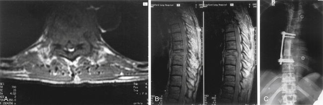
The left side is almost always used for the approach because it is safer and easier to visualize, dissect, and mobilize the aorta and segmental vessels than the vena cava or azygous venous system. It is easier to repair an injured aorta than the vena cava. One should consider obtaining a preoperative axial CT or MRI to assess the location of the aorta. If the aorta is lying very far lateral to the left (Fig. 146-3) or if the pathology is strictly right sided, a right-sided approach can be performed. A standard thoracotomy incision is used beginning approximately two fingerbreadths below the angle of the scapula and coursing ventrally to the midaxillary line. One should select the intercostal space directly over the level of pathology to enter the pleural cavity. We have had satisfactory experience in performing a retropleural thoracotomy. In this procedure, the surgeon separates the endothoracic fascia from the parietal pleura, and the dissection is made down to the rib heads and spine extrapleurally. This is technically more difficult but can obtain a transthoracic approach without the need for a postoperative chest tube. A postoperative radiograph in the recovery room is essential to rule out a significant undetected pneumothorax.
Thoracolumbar Junction
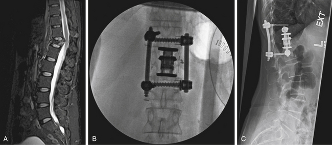
For lesions affecting T10 through the upper lumbar spine (L1), a combined thoracoabdominal approach is necessary (Fig. 146-4). This may be true for lesions at L2 that require exposure to the T12-L1 disc space for instrumentation. During a standard thoracotomy, the patient is positioned in the right lateral decubitus position with a bend in the table to facilitate exposure. A double-lumen endotracheal tube is used for ipsilateral lung deflation. The incision is commonly made over the 10th rib and carried from the anterior axillary line to the posterior axillary line and extended as needed. The oblique and transversus abdominis muscles are incised, but care should be taken not to enter the peritoneal cavity. A subperiosteal dissection of the rib allows for efficient resection of the rib. The thoracic cavity is entered via the 10th or 11th rib space, and the diaphragm is immediately identified. The parietal pleura and peritoneal sac are bluntly mobilized by using finger- and sponge-stick dissection. Avoiding the monopolar cautery for most of this stage can prevent inadvertent entry into the peritoneal cavity, lung, or abdominal viscera. The diaphragm is mobilized from its peripheral attachment to the 11th rib. A 2- to 3-cm cuff of diaphragmatic tissue is maintained to allow for reapproximation during closure. The spinal attachments of the diaphragm are taken down sharply or with monopolar cautery. The medial attachment of the lateral arcuate ligament and the lateral attachment of the medial arcuate ligament are divided close to the tip of the transverse process of L1. The crus of the diaphragm is divided 2 to 3 cm away from the vertebral body and should be tagged. At this point, large self-retaining chest retractors can be placed to displace the peritoneal contents and diaphragm. Vessels that require sacrifice should be taken as close to the aorta or vena cava as possible to allow for maximal mobilization of these structures. Coagulation near the neuroforamen should be avoided to decrease the risk of compromising important radicular feeders to the spinal cord. The psoas muscle can be sharply dissected with periosteal elevators or monopolar cautery back to the attachments to the pedicle to maximize exposure of the lumbar vertebral bodies. Gentle retraction can allow exposure from T9 through L3.
Retroperitoneal Approach
Administration of cathartic agents before surgery and placement of a nasogastric tube during induction of anesthesia may facilitate easier retraction of the peritoneal contents during the case. Positioning for the retroperitoneal approach is similar to that for the thoracoabdominal exposure: the patient is in the lateral position with a break in the table at the level of the pathology. Upper lumbar exposure may require resection of the 12th rib. The incision is typically made from the lateral margin of the dorsal longitudinal paraspinal muscles (e.g., iliocostalis, sacrospinalis) and extends ventrally to the lateral border of the rectus abdominis muscles. The external and internal oblique and transversus abdominis muscles are divided with monopolar cautery. Clamp dissection and elevation of these muscles before incision can avoid entry into the peritoneal cavity. Blunt dissection with a sponge-on-a-stick can mobilize the peritoneum away from the spine. Great care must be taken to avoid damage to the ureter, although it is usually safely reflected ventrally with the peritoneal contents. Large, self-retaining table-mounted retractors (e.g., Omni, Thompson-Farley) are used over moist laparotomy sponges to maintain exposure. The transverse processes are palpable through the psoas muscle. This muscle can be dissected from its periosteal attachments by using monopolar cautery. This bovie technique results in less blood loss than a Cobb or periosteal elevator. Vigorous attempts at retraction with a Meyerding or similar retractor may cause laceration of the muscle and excessive bleeding. Careful “toeing-in” of the Meyerding or McElroy retractor is all that is usually necessary to put the psoas on stretch and facilitate subperiosteal exposure. Too much stretch, however, may cause postoperative psoas or iliopsoas weakness and pain. Mobilization of this muscle dorsally to the pedicle allows palpation and visualization of the ventral border of the spinal canal. Key points regarding closure of the retroperitoneal exposure include meticulous closure of the abdominal wall muscular layers to prevent hernia formation. We recommend leaving a large Hemovac drain in the retroperitoneal space for 24 to 48 hours, especially when decortication or resection of vertebral bone causes significant oozing of blood still seen at the time of closure. Another potential complication of this approach is intestinal ileus. Nasogastric suction is continued postoperatively until bowel activity is confirmed.
Transabdominal (Transperitoneal) Approach
Ventral decompression, reconstruction, and fixation of the lower lumbar spine and lumbosacral junction via the transperitoneal approach (open or laparoscopic) are possible.15–17 Threaded interbody titanium cages, bone dowels, and other synthetic implants are available for interbody fusion and/or fixation. Typical thoracolumbar bone screws, plates, and rods are difficult to insert from this approach and have a high profile near vascular structures. The exposure tends to be triangular in shape because the field of view limited by the bifurcation of the iliac vessels and the L5-S1 disc space. Direct ventral screw fixation (e.g., buttress screw) of the upper sacrum is possible after a subperiosteal exposure of S1 immediately caudal to the disc space is performed. Use of Steinmann pins or a table-mounted vascular retractor is useful in retracting the iliac veins and arteries. Blunt dissection and avoidance of the monopolar cautery may avoid damage to the superior hypogastric plexus (and associated retrograde ejaculation). The L5-S1 disc space is readily evacuated, and bone graft and/or implants can be inserted.
L5 vertebrectomy has been accomplished via the open, laparoscopic, or retroperitoneal approach, but the procedure is difficult and carries a higher risk of vascular injury than discectomy.18,19 Furthermore, reconstruction of L5 from the direct anterior transperitoneal approach is also very difficult. Vertebrectomy of L4 is similarly very difficult from the anterior approach and can be more readily accomplished via the retroperitoneal approach. The midlumbar and upper lumbar levels (L3-4, L2-3, L1-2) are more difficult to expose via a transperitoneal approach because of the bulk of abdominal contents that must be retracted. The retroperitoneal approach should be considered.
Lateral Retroperitoneal Transpsoas Approach
This approach allows access to the lumbar spine via a lateral approach that passes through the retroperitoneal fat and psoas major muscle (Fig. 146-5). Variations of this approach include the minimally invasive extreme lateral interbody fusion (XLIF) or direct lateral interbody fusion (DLIF) approaches.
Fracture Reduction
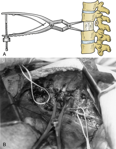
Several ventral thoracolumbar instrumentation systems have bolts that (once placed in the adjacent vertebral bodies) can be used with a distractor to accomplish reduction and distraction. Distraction is effective, but the distractor can obscure the surgeon’s view and compromise access to the decompression site during placement of the bone graft. Interspace spreaders have the same limitation, although newer models are longer and more streamlined, allowing greater accessibility to the vertebrectomy site during distraction and reconstruction (Fig. 146-6). When combined with ligamentotaxis from the PLL, anterior distraction maneuvers can be an effective method to reduce posteriorly displaced fractures.
A fourth method to reduce posteriorly displaced fracture fragments is an eggshell osteotomy. The cancellous portion of the fractured vertebral body is removed with a high-speed drill, leaving the cortical remnants. The posteriorly displaced cortical fragments can then be pulled anteriorly by using reverse-angle and straight curets.
Bone Grafts and Vertebral Body Replacements
Autologous tricortical iliac crest provides satisfactory axial support. Harvest of large tricortical graft endangers the peritoneal contents. Great care should be taken during periosteal dissection. Significant morbidity can be associated with harvest of autologous iliac crest bone. We typically use a unipolar cautery with the tip angled ventrally to hug the dorsal cortex during stripping of the muscular and fascial attachments. A Cobb elevator is also useful, but it is necessary to take care to avoid plunging into the peritoneum. Vessels perforating the iliac crest must be coagulated or the emissary ostia treated with bone wax to help prevent accumulation of a hematoma. One should always stay one to two fingerbreadths dorsal to the anterior superior iliac spine to avoid injury to the lateral femoral cutaneous nerve. If one desires to reconstruct the defect in the iliac crest, both natural and artificial methods are possible. If rib is available, the ends can be impacted into the harvest site sides of the iliac crest to recreate the superior contour. Steinmann pins or screws (titanium or stainless steel) as a support for methylmethacrylate may be used.20 If the latter technique is used, a postoperative drain is recommended, as the cement will elicit a collection of serous fluid.
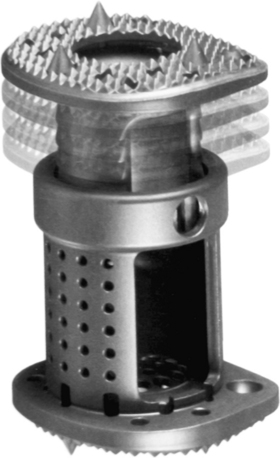
In addition to autograft or allograft bone, methylmethacrylate and artificial bone spacers are currently being marketed. Vertical mesh titanium cages (Pyramesh, Medtronic Sofamor Danek, Memphis, TN; Harms, DePuy Spine, Raynham, MA; SynMesh System, Synthes Spine, Paoli, PA), carbon fiber cages (Stackable Cage System, DePuy Spine), polyether ether blocks (PEEK, Medtronic Sofamor Danek), and expandable metallic implants (Synex System, Synthes Spine [Fig. 146-7]; VertiSpan, Medtronic Sofamor Danek [Fig. 146-8]) are available.
The importance of meticulous shaping and “carpentry” with the graft during this step cannot be overemphasized. A spinal metal implant is not a substitute or savior for a poorly shaped or fitted bone graft.
Instrumentation
Cable Systems
The Dwyer cable system was first developed in the early 1960s for application to the convex side of thoracolumbar scoliotic curves. The basic principle of ventrolateral correction of scoliosis is to shorten the convexity by applying compressive forces. A screw with a staple (to maintain screw position and prevent movement) is placed on the convex side of a curve into the vertebral body on the lateral side. A titanium cable is then connected to the screws and tightened to create a compressive force. Excessive force, however, can produce undesirable thoracic kyphosis or, further caudally in the spine, the flattening of a normal lumbar lordosis. Dwyer reported a 43% complication rate, including screw pull-out and vascular or visceral injuries. This system can be used for degenerative lumbar curves, but it is not recommended in flat back or kyphotic deformities. This particular type of implant system has been abandoned by many surgeons in favor of rod and plate systems.
Rod Systems
Kaneda System
A unique aspect of the Kaneda system (DePuy Spine; Fig. 146-9) is the tetra-plate with four corner spikes that is initially hammered into the center of the lateral aspect of the vertebral body. One should “garden” the spine to ensure flush contact between the staple plate and the bone. Two vertebral (preferably bicortical) screws are placed through each plate. The heads of the screws have a channel through which rods are placed. The design of the staple plate is such that the ventral screw holes are more rostral and caudal in the upper and lower plates, respectively. Thus, the ventral span of the rod is longer than the dorsal. The heads of these screws can be engaged by a distractor for placement of the strut graft. The Kaneda distraction system is very effective and allows ample working space through which the bone graft can be placed. Cross-fixators are available to enhance the rigidity of this implant. This device is very effective for short (one or two) segment fixation for a variety of pathologies. Sources of complication include failure to achieve maximal surface area contact between the staple plate and bone (by allowing rocking of the metal over a bony prominence) and placement of screws that are either too short or too long. Preoperative axial CT slices (bone windows) can be used to indirectly measure the length of screw needed. One can usually feel the screw engaging the opposite lateral cortex. Inadequate countersinking of the graft may make it difficult to apply a cross-link.
Antares Dual-Rod System
The Antares dual-rod system (Medtronic Sofamor Danek) is very similar to the Kaneda system. An anchoring plate with cleats is inserted into the side of the vertebral bodies above and below. Bolts are then placed through holes in the plates and across the vertebral bodies. Rods are slid into the bolts and compressed, and locking screws are tightened. Cross-links are available.
Plate Systems
Z-Plate System
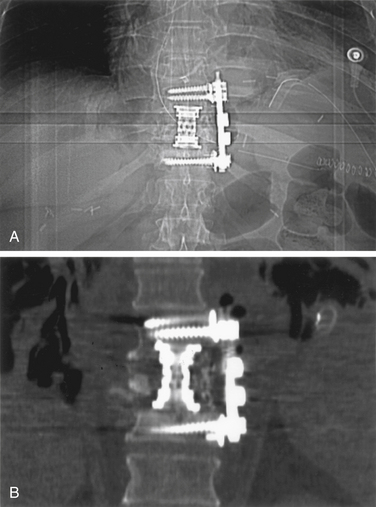
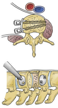
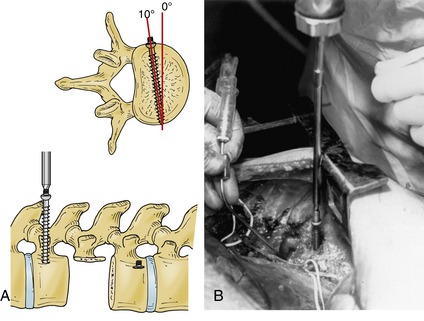
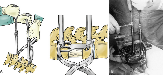
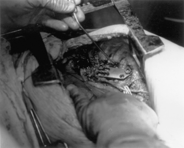
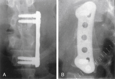
The Z-plate system (Medtronic Sofamor Danek), designed by Zdeblick (Figs. 146-10 to 146-12), combines the low-profile advantage of plates with the distraction and compression capability of vertebral body screws. Bicortical purchase is recommended, and a combination of bone screws and bolts is used to rigidly lock to the plate. Dorsally, screws are placed 10 degrees ventrally away from the canal. The starting point for the rostral body is 8 to 10 mm inferior and ventral to the upper dorsal corner of the vertebral body on lateral exposure. Conversely, the entry point for the caudal bolt is 8 to 10 mm superior and ventral to the lower dorsal corner of the vertebral body. An awl is used to pierce the cortex, but the bone is not tapped. These bolts can be used for distraction and allow for placement of a strut graft and correction of kyphosis. In patients with suboptimal bone strength, it is useful to use (initially) an intervertebral body spreader to apply force over a broader area. When the strut graft is in place, the bolts can be compressed and locked rigidly to the plate. As a last step, cancellous bone screws are placed through the ventral slots in the plate and angled 10 degrees dorsally. These screws are typically 5 mm longer than the dorsally placed bolts because of the configuration of the vertebral body. Complications can arise from placing a plate that is too long and that extends above or below, across, or into a disc space. This may accelerate degeneration at that motion segment. The usual risks of bicortical screw placement also apply. One must also make sure that the bolts, and especially the bone screws, are not angled down or up into the graft or adjacent disc. The latest version of the Z-plate allows for rigid fixation of the screw heads to the plate.
Anterior Thoracolumbar Locking Plate System
The Synthes plate system (Fig. 146-13) is also low profile and composed of titanium (MRI compatible). It differs from the Z-plate system in that distraction forces are not applied to the bolts or screws but are applied directly to the vertebral body end plates. Synthes makes a long-handled distractor with strong but thin blades that allows perhaps the best access to the graft site during placement of the strut. Once the graft is in place, angled screw hole trajectories in the plate cause up to 3 mm of compression as the screws are driven into the bone. This system uses wide, cancellous screws for unicortical purchase, although bicortical purchase is an option. Because placement is unicortical, equal-length screws are used dorsally and ventrally. This system has the advantage of being able to effectively provide distraction and compression, is low profile, and is perhaps the simplest in design. It is limited in the amount of compression (2 to 3 mm) provided by the dorsal compression screws. This system is no longer in widespread use.
Interbody (Disc Space) Metallic Devices
It may be difficult to assess fusion in the postoperative state because of the artifact from the implants. CT scans with sagittal reconstruction through the middle of the implants can be useful. Flexion and extension radiographs can determine whether pathologic motion is present but cannot directly assess the degree of arthrodesis. Despite these issues, long-term success has been reported.21
Alleyne C.H., Rodts G.E., Haid R.W. Corpectomy and stabilization with methylmethacrylate in patients with metastatic disease of the spine. J Spinal Disord. 1995;8(6):439-443.
Muhlbauer M., Pfisterer W., Eyb R., et al. Minimally invasive retroperitoneal approach for lumbar corpectomy and anterior reconstruction. J Neurosurg. 2000;93(Suppl 1):161-167.
Rodts G.E., McLaughlin M.R., Zhang J.Y., et al. Laparoscopic anterior lumbar interbody fusion. Clin Neurosurg. 2000;47:541-556.
Rrajaraman V., Vingan R., Roth P., et al. Visceral and vascular complications resulting from anterior lumbar interbody fusion. J Neurosurg. 1999;91(Suppl 1):60-64.
1. Royle N.D. The operative removal of an accessory vertebra. Med J Australia. 1928;1:467-468.
2. Ito H., Tsuchiya J., Asami G. A new radical operation for Pott’s disease. J Bone Joint Surg. 1934;16:499-515.
3. Hodgson A.R., Stock F.E. Anterior spinal fusion. A preliminary communication on radical treatment of Pott’s disease and Pott’s paraplegia. Br J Surg. 1956;44:266-275.
4. Humphries A.W., Hawk W.A., Berndt K.L. Anterior fusion of the lumbar spine using an internal fixation device. J Bone Joint Surg [Am]. 1959;41:371.
5. Dwyer A.P., Newton N.C., Sherwood A.A. Anterior approach to scoliosis. Clin Orthop Relat Res. 1969;62:192-202.
6. Dwyer A.P., O’Brien J.P., Seal P.P., et al. The late complications after the Dwyer anterior spinal instrumentation for scoliosis. J Bone Joint Surg [Br]. 1977;59:117.
7. Dwyer A.P., Schafer M.F. Anterior approach to scoliosis: results of treatment in 51 cases. J Bone Joint Surg [Br]. 1974;56:218-224.
8. Zielke K., Stukat R., Beaujean M.A. Derotation and fusion-anterior spinal instrumentation. Orthop Trans. 1978;1:270.
9. Brown L.P., Bridwell K.H., Holt R.T., et al. Aortic erosions and lacerations associated with the Dunn anterior spinal instrumentation. Orthop Trans. 1986;10:16-17.
10. Bracken M.B., Shepard M.J., Collins W.F., et al. A randomized, controlled trial of methylprednisolone or naloxone in the treatment of acute spinal cord injury. N Engl J Med. 1990;322:1405-1411.
11. Bracken M.B., Shepard M.J., Collins W.F., et al. Methylprednisolone or naloxone treatment after acute spinal cord injury: 1-year follow up data. J Neurosurg. 1992;76:23-31.
12. Forbes H.J., Allen P.W., Waller C.S., et al. Spinal cord monitoring in scoliosis surgery. J Bone Joint Surg [Br]. 1974;73:487-491.
13. Goto T., Crosby G. Anesthesia and the spinal cord. Anesthes Clin North Am. 1992;10:493-519.
14. Levy W.J., York D.H. Evoked potentials from the motor tracts in humans. Neurosurgery. 1983;12:422-429.
15. McLaughlin M., Comey C.H., Haid R.W., et al. Laparoscopic anterior lumbar interbody fusion. Contemp Neurosurg. 1998;20:1-9.
16. McLaughlin M.R., Zhang J.Y., Subach B.R., et al. Laparoscopic anterior lumbar interbody fusion. Neurosurg Focus. 1999;7(6):E8.
17. Rodts G.E., McLaughlin M.R., Zhang J.Y., et al. Laparoscopic anterior lumbar interbody fusion. Clin Neurosurg. 2000;47:541-556.
18. Muhlbauer M., Pfisterer W., Eyb R., et al. Minimally invasive retroperitoneal approach for lumbar corpectomy and anterior reconstruction. J Neurosurg. 2000;93(Suppl 1):161-167.
19. Rrajaraman V., Vingan R., Roth P., et al. Visceral and vascular complications resulting from anterior lumbar interbody fusion. J Neurosurg. 1999;91(Suppl 1):60-64.
20. Alleyne C.H., Rodts G.E., Haid R.W. Corpectomy and stabilization with methylmethacrylate in patients with metastatic disease of the spine. J Spinal Disord. 1995;8(6):439-443.
21. Brantigan J.W., Steffee A.D. A carbon fiber implant to aid interbody fusion. Spine. 1993;18:2106-2117.
[/level-membership-for-neurosurgery-category][not-level-membership-for-neurosurgery-category]
Chapter 146 Ventral and Lateral Thoracic and Lumbar Fixation Techniques
Surgery on the ventral thoracic and lumbar spine began nearly 100 years ago. Ventral approaches for decompression of spinal pathology were first attempted in the early 1900s. Pioneers such as Royle1 excised hemivertebrae for the treatment of scoliosis. Ito2 as well as Hodgson and Stock3 refined the ventral (transperitoneal) approach to the thoracolumbar spine for the treatment of Pott disease. These early efforts to decompress ventral spinal pathology were frequently complicated by postoperative mechanical instability and progressive deformity.
The first reports of ventral instrumentation of the spine were from Humphries,4 who developed ventral interbody fusion with ventral plates and unicortical screws. These devices provided little biomechanical advantage. Most of these cases were transperitoneal approaches for debridement and stabilization in patients with Pott disease. The transperitoneal approach was eventually replaced by the retroperitoneal or extracavitary approaches for lesions of the lower thoracic and lumbar spine.
Throughout the 1970s, the preferred treatment for traumatic injuries was dorsal fusion and instrumentation, combined with ventral decompression and fusion. The Dwyer5–7 and Zielke8 devices were developed as ventrolateral implants that could augment or replace dorsal instrumentation. These consisted of screws that traversed the vertebral body that were interconnected with cable (Dwyer) or threaded rods (Zielke) that could be tightened in tension. These devices had limited ability to fixate two-column traumatic injuries. The Dunn device (developed in the late 1970s) represented a more rigid instrument for use in burst fractures. This double-screw, double-threaded rod device provided excellent strength but was removed from the market in 1986 after reports of great vessel erosion and rupture.9
Biomechanical Considerations
Certain biomechanical characteristics of implant systems are important to understand. Rigid implants (e.g., Z-plate, Kaneda systems, Expedium Anterior system, and M-8 dual-rod system) theoretically allow for greater immobilization of the spine. If the implant bears most of the stress, there is a risk of implant breakage or failure. Some plate systems have set screw holes rather than slots, thereby creating a static (nondynamic) condition beginning at the time of plate fixation. Also, stress shielding provided by the rigid fixation may prevent the beneficial compressive forces from enhancing bone fusion (Wolff’s law). Because bone is a biologic, deformable material, repeated stress loading may cause bony erosion and failure at the metallic implant-bone interface.
Indications for Ventrolateral Instrumentation
Anterior and middle column trauma (with preservation of the dorsal elements) may be treated adequately with a ventral approach (Fig. 146-1). Failure to recognize significant posterior column injury may result in delayed kyphotic deformity and neurologic deterioration. There are few clinical outcome data to encourage ventral decompression of trauma patients with complete neurologic loss below the level of the lesion. Ventral approaches, however, may be useful in paraplegic patients with a severe kyphotic deformity. Anterior reconstruction may provide better sagittal balance that could be important for long-term pulmonary function, independent transferring, and upper extremity function.
Inadequate radiographic studies before surgery can lead to intraoperative or postoperative complications. Plain radiographs are essential and should include flexion and extension views when there is any suspicion of mechanical instability. In addition, attention should be paid to the density of bone as well as the sagittal and coronal alignment. Patients with scoliosis should have complete 36-inch standing films to assess overall spinal balance. The value of sagittal reconstruction of CT images is often overlooked, particularly after myelographic dye injection. Axial CT may be preferable over MRI to determine the amount of bony spinal canal compromise in trauma. Sagittal MRI often provides excellent views of the PLL. If intact, one may consider use of ligamentotaxis to reduce a burst fracture fragment. MRI has the added advantage of showing signs of soft dorsal tissue injury and hematoma that would commonly go unrecognized with plain radiographs and CT scan alone. Although cost-effectiveness is a primary concern, any patient with complex spinal pathology (and for whom aggressive surgery is contemplated) may require both CT and MRI as part of the workup.
Ventral Surgical Techniques
Positioning
Complications arising from the lateral decubitus position can also be averted with due diligence. We have all placed patients on a bean bag, but the bag must not extend into the axilla of the down arm. A roll (a liter bag of IV solution wrapped in a towel suffices) is placed above the edge of the bean bag just below the axilla. The peroneal nerve in the down leg must be protected with foam and/or gel padding over the fibular head. A pillow is placed between the legs, which are flexed 45 degrees at the hip and knees. The coronal plane of the patient’s thorax must be perpendicular to the floor. Wide tape should be used to secure this position to allow rotation of the bed along its long axis (“airplaning”). Establishing this position assists the surgeon in remaining oriented throughout the procedure, especially during the critical steps of decompressing the spinal cord or placing a vertebral body screw. Some tables are equipped with a compass so that the desired neutral position can be recorded and reset by the anesthesiologist if an “airplane” maneuver is necessary. The perpendicular orientation of the coronal patient plane relative to the floor also allows for more efficient manual reduction of a kyphotic deformity by pressing on the back. The authors routinely “break” or flex the table at the level of the pathology to help open the disc spaces laterally and aid in the insertion of the bone graft (Fig. 146-2). Flexing the table also helps open the space between the 12th rib and the iliac crest. Once the bone graft is in place, the anesthesiologist is asked to return the table to the neutral, unflexed position.
We routinely administer suitable gram-positive antibiotic coverage (e.g., cefazolin 1 g or nafcillin 1 g). In cases of traumatic cord contusion or cord compression caused by tumor, we consider the use of methylprednisolone at least 1 hour before surgery. Using the spinal cord contusion protocol, the patient may receive a bolus of 30 mg/kg over 45 minutes followed by continuous infusion of 5.4 mg/kg per hour for 23 hours.10,11
Paralytic agents are not used after induction to allow for motor response in the event of inadvertent nerve or spinal cord stimulation. The role of somatosensory-evoked potential (SSEP) monitoring is debatable. A decrease in SSEP amplitude of more than 50% and limited or absent intraoperative recovery of amplitude are predictors of a postoperative neurologic deficit.12,13 Despite this reasonable sensitivity and low-false negative rate, SSEP monitoring measures only dorsal column function. False positives are common and often related to anesthetic considerations that can lead to a dangerous desensitization of the surgeon to warnings of intraoperative injury. SSEPs may be useful in deformity cases in which distractive or compressive forces are anticipated and could be reversed.
Motor-evoked potentials may be more accurate than SSEPs in monitoring spinal cord motor function during surgery.14 This technique is extremely sensitive to anesthetics and requires expertise on the part of the anesthesiologist and monitoring team.
Approach and Exposure
Upper Thoracic Spine
Ventral exposure of the rostral levels of the thoracic spine is challenging. The first and second thoracic vertebrae usually can be approached ventrally with a low diagonal or transverse cervical incision. A vertical split of the manubrium often allows exposure down to T3 without sacrificing significant bone. A preoperative sagittal MRI should be obtained and inspected to ensure that the aortic arch does not block ventral access to the T2-3 area. Furthermore, one must be cognizant of the course of the recurrent laryngeal nerve as it emerges dorsal to the brachiocephalic arch to pass between the esophagus and trachea. Although its course is more constant on the left side, low-lying incisions to approach T1 and T2 on the left side put the thoracic duct at risk. This structure is intimately related to the subclavian vein off midline on the left and must be protected. Unrecognized pneumothorax is a complication of this approach because the pleura overlying the medial aspect of the cupola of the lung is adjacent to the spine. Filling the wound with saline and performing a positive pressure inspiration (Valsalva maneuver) at the close of the case is an essential step during closure. An oscillating saw or Gigli saw can be used to remove larger portions of the manubrium, but the retromanubrial space must be palpated to ensure that the brachiocephalic trunk is free. With the patient in the supine position, the upper thoracic spine slopes away from the surgeon, beginning at the T1-2 interspace. It can be difficult to place a ventral plate and screws in this region without a more aggressive removal or splitting of the manubrium or sternum.
Midthoracic Spine
The left side is almost always used for the approach because it is safer and easier to visualize, dissect, and mobilize the aorta and segmental vessels than the vena cava or azygous venous system. It is easier to repair an injured aorta than the vena cava. One should consider obtaining a preoperative axial CT or MRI to assess the location of the aorta. If the aorta is lying very far lateral to the left (Fig. 146-3) or if the pathology is strictly right sided, a right-sided approach can be performed. A standard thoracotomy incision is used beginning approximately two fingerbreadths below the angle of the scapula and coursing ventrally to the midaxillary line. One should select the intercostal space directly over the level of pathology to enter the pleural cavity. We have had satisfactory experience in performing a retropleural thoracotomy. In this procedure, the surgeon separates the endothoracic fascia from the parietal pleura, and the dissection is made down to the rib heads and spine extrapleurally. This is technically more difficult but can obtain a transthoracic approach without the need for a postoperative chest tube. A postoperative radiograph in the recovery room is essential to rule out a significant undetected pneumothorax.
[/not-level-membership-for-neurosurgery-category]
