[level-membership-for-anesthesiology-category]
Ventilators
Classification of ventilators
There are many ways of classifying ventilators (Table 8.1).
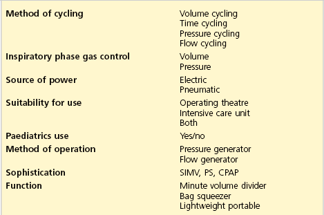
1. The method of cycling is used to change over from inspiration to exhalation and vice versa:
a) volume cycling: when the predetermined tidal volume is reached during inspiration, the ventilator changes to exhalation
b) time cycling: when the predetermined inspiratory duration is reached, the ventilator changes to exhalation. The cycling is not affected by the compliance of the patient’s lungs. Time cycling is the most commonly used method
c) pressure cycling: when the predetermined pressure is reached during inspiration, the ventilator changes over to exhalation. The duration needed to achieve the critical pressure depends on the compliance of the lungs. The stiffer the lungs are, the quicker the pressure is achieved and vice versa. The ventilator delivers a different tidal volume if compliance or resistance changes
d) flow cycling: when the predetermined flow is reached during inspiration, the ventilator changes over to exhalation. This method is used in older design ventilators.
2. Inspiratory phase gas control:
3. Source of power – can be electric or pneumatic.
4. Suitability for use in theatre and/or intensive care.
5. Suitability for paediatric practice.
6. Method of operation (pattern of gas flow during inspiration):
a) pressure generator: the ventilator produces inspiration by generating a constant and predetermined pressure. Bellows or a moderate weight produce the pressure. The inspiratory flow changes with changes in lung compliance (Table 8.2)
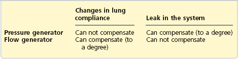
b) flow generator: the ventilator produces inspiration by delivering a predetermined flow of gas. A piston, heavy weight or compressed gas produce the flow. The flow remains unchanged by changes in lung compliance, although pressures will change (see Table 8.2). These ventilators have a high internal resistance to protect the patient from high working pressures.
7. Sophistication: new ventilators can function in many of the above modes. They have other modes, e.g. SIMV, PS and CPAP (see pp 224–225).
a) minute volume dividers: fresh gas flow (FGF) powers the ventilator. The minute volume equals the FGF divided into preset tidal volumes thus determining the frequency
b) bag squeezers replace the hand ventilation of a Mapleson D or circle system. They need an external source of power
c) lightweight portable: powered by compressed gas and consists of the control unit and patient valve.
Characteristics of the ideal ventilator
1. The ventilator should be simple, portable, robust and economical to purchase and use. If compressed gas is used to drive the ventilator, a significant wastage of the compressed gas is expected. Some ventilators use a Venturi to drive the bellows, to reduce the use of compressed oxygen.
2. It should be versatile and supply tidal volumes up to 1500 mL with a respiratory rate of up to 60/min and variable I : E ratio. It can be used with different breathing systems. It can deliver any gas or vapour mixture. The addition of positive end expiratory pressure (PEEP) should be possible.
3. It should monitor the airway pressure, inspired and exhaled minute and tidal volume, respiratory rate and inspired oxygen concentration.
4. There should be facilities to provide humidification. Drugs can be nebulized through it.
5. Disconnection, high airway pressure and power failure alarms should be present.
6. There should be the facility to provide other ventilatory modes, e.g. SIMV, CPAP and pressure support.
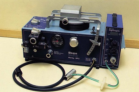
Manley MP3 ventilator
This is a minute volume divider (time cycled, pressure generator). All the FGF (the minute volume) is delivered to the patient divided into readily set tidal volumes (Fig. 8.1).
Components
1. Rubber tubing delivers the FGF from the anaesthetic machine to the ventilator.
2. Two sets of bellows. A smaller time-cycling bellows receives the FGF directly from the gas source and then empties into the main bellows.
3. Three unidirectional valves.
4. An adjustable pressure limiting (APL) valve with tubing and a reservoir bag used during spontaneous or manually controlled ventilation.
5. The ventilator has a pressure gauge (up to 100 cm H2O), inspiratory time dial, tidal volume adjuster (up to 1000 mL), two knobs to change the mode of ventilation from and to controlled and spontaneous (or manually controlled) ventilation. The inflation pressure is adjusted by sliding the weight to an appropriate position along its rail. The expiratory block is easily removed for autoclaving.
Mechanism of action
1. The FGF drives the ventilator.
2. During inspiration, the smaller bellows receives the FGF, while the main bellows delivers its contents to the patient. The inspiratory time dial controls the extent of filling of the smaller bellows before it empties into the main bellows.
3. During expiration, the smaller bellows delivers its contents to the main bellows until the predetermined tidal volume is reached to start inspiration again.
4. Using the ventilator in the spontaneous (manual) ventilation mode changes it to a Mapleson D breathing system.
Problems in practice and safety features
1. The ventilator ceases to cycle and function when the FGF is disconnected. This allows rapid detection of gas supply failure.
2. Ventilating patients with poor pulmonary compliance is not easily achieved.
3. It generates back pressure in the back bar as it cycles.
4. The emergency oxygen flush in the anaesthetic machine should not be activated while ventilating a patient with the Manley.
Penlon Anaesthesia Nuffield Ventilator Series 200
This is an intermittent blower ventilator. It is small, compact, versatile and easy to use with patients of different sizes, ages and lung compliances. It can be used with different breathing systems (Fig. 8.2). It is a volume-preset, time-cycled, flow generator in adult use. In paediatric use, it is a pressure-preset, time-cycled, flow generator.
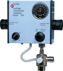
Fig. 8.2 The Penlon Nuffield 200 ventilator. (Courtesy of Penlon Ltd, Abingdon, UK (www.penlon.com).)
Components
1. The control module, consisting of an airway pressure gauge (cm H2O), inspiratory and expiratory time dials (seconds), inspiratory flow rate dial (L/s) and an on/off switch. Underneath the control module there are connections for the driving gas supply and the valve block. Tubing connects the valve block to the airway pressure gauge.
2. The valve block has three ports:
a) a port for tubing to connect to the breathing system reservoir bag mount
b) an exhaust port which can be connected to the scavenging system
3. The valve block can be changed to a paediatric (Newton) valve.
Mechanism of action
1. The ventilator is powered by a driving gas independent from the FGF. The commonly used driving gas is oxygen (at about 400 kPa) supplied from the compressed oxygen outlets on the anaesthetic machine. The driving gas should not reach the patient as it dilutes the FGF, lightening the depth of anaesthesia.
2. It can be used with different breathing systems such as Bain, Humphrey ADE, T-piece and the circle. In the Bain and circle systems, the reservoir bag is replaced by the tubing delivering the driving gas from the ventilator. The APL valve of the breathing system must be fully closed during ventilation.
3. The inspiratory and expiratory times can be adjusted to the desired I/E ratio. Adjusting the inspiratory time and inspiratory flow rate controls determines the tidal volume. The inflation pressure is adjusted by the inspiratory flow rate control.
4. With its standard valve, the ventilator acts as a time-cycled flow generator to deliver a minimal tidal volume of 50 mL. When the valve is changed to a paediatric (Newton) valve, the ventilator changes to a time-cycled pressure generator capable of delivering tidal volumes between 10 and 300 mL. This makes it capable of ventilating premature babies and neonates. It is recommended that the Newton valve is used for children of less than 20 kg body weight.
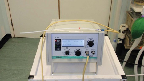
Bag in bottle ventilator
Modern anaesthetic machines often incorporate a bag in bottle ventilator.
Components
1. A driving unit consisting of:
a) a chamber (Fig. 8.3) with a tidal volume range of 0–1500 mL (a paediatric version with a range of 0–400 mL exists)
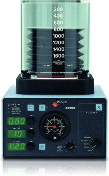
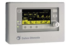
2. A control unit with a variety of controls, displays and alarms: the tidal volume, respiratory rate (6–40/min), I/E ratio, airway pressure and power supply (Figs 8.3 and 8.4).
Mechanism of action
1. It is a time-cycled ventilator.
2. Compressed air is used as the driving gas (Fig. 8.5). On entering the chamber, the compressed air forces the bellows down, delivering the fresh gas to the patient (the fresh gas is accommodated in the bellows).
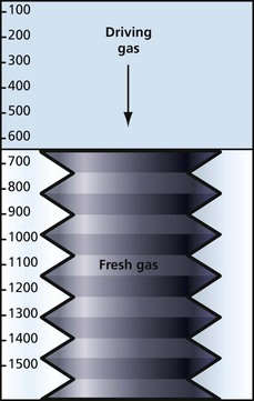
3. The driving gas and the fresh gas remain separate.
4. The volume of the driving gas reaching the chamber is equal to the tidal volume.
Problems in practice and safety features
1. Positive pressure in the standing bellows causes a PEEP of 2–4 cm H2O.
2. The ascending bellows collapses to an empty position and remains stationary in cases of disconnection or leak.
3. The descending bellows hangs down to a fully expanded position in a case of disconnection and may continue to move almost normally in a case of leakage.
Servo-i ventilator
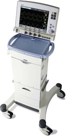
Mechanism of action
1. Gas flow from the oxygen and air inlets is regulated by their respective gas modules.
2. Oxygen concentration is measured by an oxygen cell.
3. The pressure of the delivered gas mixture is measured by the inspiratory pressure transducer.
4. The patient’s expiratory gas flow is measured by ultrasonic transducers and the pressure measured by the expiratory pressure transducer.
5. PEEP in the patient system is regulated by the expiratory valve.
There are various modes of ventilation available:
1. Synchronized intermittent mandatory ventilation (SIMV). The ventilator provides mandatory breaths, which are synchronized with the patient’s respiratory effort (if present). The type of mandatory breath supplied depends on the setting selected. Usually one of the following is selected:
a) pressure-regulated volume control (PRVC): a preset tidal volume is delivered but limited to 5 cm H2O below the set upper pressure limit. This automatically limits barotrauma if the upper pressure limit is appropriately set. The flow during inspiration is decelerating. The patient can trigger extra breaths
b) volume control: a preset tidal volume and respiratory rate are selected. The breath is delivered with constant flow during a preset inspiratory time. The set tidal volume will always be delivered despite high airway pressures if the patient’s lungs are not compliant. To prevent excessive pressures being generated in this situation, the upper pressure limit must be set to a suitable level to prevent barotrauma
c) pressure control: a pressure control level above PEEP is selected. The delivered tidal volume is dependent upon the patient’s lung compliance and airway resistance together with the tubing and endotracheal tube’s resistance. Pressure control ventilation is preferred when there is a leak in the breathing system (e.g. uncuffed endotracheal tube) or where barotrauma is to be avoided (e.g. acute lung injury). If the resistance or compliance improves quickly, there is a risk of excessive tidal volumes being delivered (volutrauma) unless the pressure control setting is reduced.
2. Supported ventilation modes: once the patient has enough respiratory drive to trigger the ventilator, usually one of the following modes is selected in addition to the PEEP setting:
a) volume support: assures a set tidal volume by supplying the required pressure support needed to achieve that tidal volume. It allows patients to wean from ventilatory support themselves as their lungs’ compliance and inspiratory muscle strength improves. This is shown by a gradual reduction in the peak airway pressure measured by the ventilator. Once the support is minimal, extubation can be considered
b) pressure support (PS): the patient’s breath is supported with a set constant pressure above PEEP. This will give a tidal volume that is dependent on the lung compliance and patient’s inspiratory muscle strength. The pressure support setting needs reviewing regularly to allow the patient to wean from respiratory support
c) continuous positive airway pressure (CPAP): a continuous positive pressure is maintained in the airways similar to that developed with a conventional CPAP flow generator (see Chapter 13). This differs from the conventional CPAP flow generator by allowing measurement of tidal volume, minute volume and respiratory rate, and trends can be observed also.
Problems in practice and safety features
1. A comprehensive alarm system is featured.
2. A mainstream carbon dioxide analyser is available which allows continuous inspiratory and expiratory monitoring of CO2 to be displayed if required.
3. A single battery module offers 30 minutes of ventilator use. Multiple battery modules (up to 6) can be loaded on the ventilator if a long transport journey is anticipated, allowing extended use. It is recommended at least two battery modules are loaded for even the shortest transport.
4. The ventilator is heavier (20 kg) than a dedicated transport ventilator.
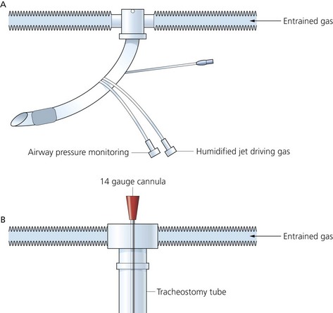
High-frequency jet ventilator
This ventilator reduces the extent of the side-effects of conventional IPPV. There are lower peak airway pressures with better maintenance of the cardiac output and less anti-diuretic hormone production and fluid retention. It is better tolerated by alert patients than conventional IPPV (Fig. 8.7).
Components
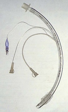
1. A Venturi injector is used: a cannula positioned in a tracheal tube (Fig. 8.8B), a cannula positioned in the trachea via the cricothyroid membrane or a modified tracheal tube with two additional small lumens opening distally (Figs 8.8A and 8.9).
2. Solenoid valves are used to deliver the jet gas.
3. Dials and display for driving pressure, frequency and inspiratory time.
4. Built-in peristaltic pump for nebulizing drugs or distilled water for humidifying the jet gas.
5. High-flow air/oxygen or nitrous oxide/oxygen blender determines the mix of the jet gas.
Mechanism of action
1. Frequencies of 20–500 cycles/min can be selected, with minute volumes ranging from 5 to 60 L/min.
2. It is a time-cycled ventilator delivering gas in small jet pulsations. The inspiratory time is adjustable from 20% to 50% of the cycle.
3. The fresh gas leaving the narrow injector at a very high velocity causes entrainment of gas. The amount of entrained gas is uncertain making measurement of tidal volume and FiO2 difficult.
4. The jet and entrained gases impact into the much larger volume of relatively immobile gases in the airway, causing them to move forward.
5. Expiration is passive. PEEP occurs automatically at a respiratory rate of over 100/min. Additional PEEP can be added by means of a PEEP valve.
VentiPAC
This is a portable ventilator used during the transport of critically ill patients (Fig. 8.10). It is a flow generator, time cycled, volume preset and pressure limited. It also acts as a pressure generator at flows below 0.25 L/s in air mix setting. ParaPAC ventilator allows synchronization of ventilation with external cardiac massage during cardiopulmonary resuscitation. A neonatal/paediatric version exists.
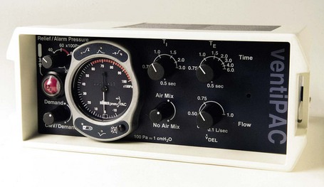
Fig. 8.10 The VentiPAC ventilator.
Components
1. A variety of controls including:
a) inspiratory flow (6–60 L/min)
b) inspiratory time (0.5–3.0 s)
c) expiratory time (0.5–6.0 s)
d) adjustable inspiratory relief pressure with an audible alarm (20–80 cm H2O)
f) a ‘demand’ and ‘CMV/demand’ control (CMV = controlled mandatory ventilation).
2. Inflation pressure monitor to measure the airway pressure.
3. 120-cm polyester or silicone 15-mm tubing with a one-way valve to deliver gases to the patient.
Mechanism of action
1. The source of power is dry, oil-free pressurized gas (270–600 kPa) at 60 L/min. Using air mix mode reduces gas consumption by the ventilator by almost 70%.
2. The frequency is set by adjusting the inspiratory and expiratory times.
3. The tidal volume is set by the adjustment of the flow and inspiratory time.
4. A choice of an FiO2 of 1.0 (no air mix) or 0.45 (air mix).
5. The demand mode provides 100% oxygen to a spontaneously breathing patient. A visual indicator flashes when a spontaneous breath is detected.
6. CMV/demand mode provides continuous mandatory ventilation. If the patient makes a spontaneous breath, this causes the ventilator to operate in a synchronized minimum mandatory ventilation (SMMV) mode. Any superimposed mandatory ventilatory attempts are synchronized with the breathing pattern.
7. A PEEP valve can be added generating a PEEP of up to 20 cm H2O.
Problems in practice and safety features
1. There is an adjustable inspiratory pressure relief mechanism with a range of 20–80 cm H2O to reduce the risk of overpressure and barotruma.
2. There are audible and visual low-pressure (disconnection) and high-pressure (obstruction) alarms.
3. A supply gas failure alarm.
4. The ventilator is magnetic resonance imaging (MRI) compatible.
Pneupac VR1 Emergency Ventilator (Fig. 8.11)
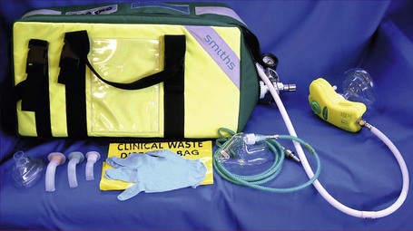
Fig. 8.11 Pneupac VR1 Emergency Ventilator.
Mechanism of action
1. The source of power is pressurized oxygen (280–1034 kPa). Using air mix prolongs the duration of use from an oxygen cylinder.
2. A constant I : E ratio of 1 : 2 with flow rates of 11–32 L/min.
3. An optional patient demand facility is incorporated allowing synchronization between patient and ventilator.
4. The linked manual controls allow the manual triggering of a single controlled ventilation. This allows the ventilator to be used in a variety of chest compression/ventilation options in cardiac life support.
5. Suitable for children (above 10 kg body weight) and adults.
Venturi injector device
A manually controlled Venturi ventilation device used during rigid bronchoscopy (Fig. 8.12). The anaesthetist and the operator share the airway. General anaesthesia is maintained intravenously.
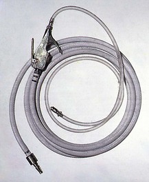
Mechanism of action
1. The high-pressure oxygen is injected intermittently through the needle placed at the proximal end of the bronchoscope.
2. This creates a Venturi effect, entraining atmospheric air and inflating the lungs with oxygen-enriched air.
3. Oxygenation and carbon dioxide elimination are achieved with airway pressures of 25–30 cm H2O.
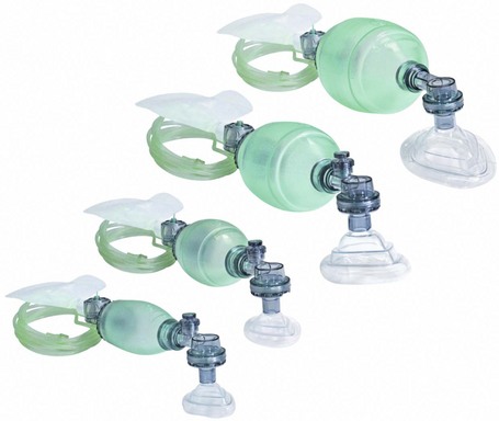
Self-inflating bag and mask
This is a means of providing manual IPPV. It is portable and is used during resuscitation, transport and short-term ventilation (Fig. 8.13).
Components
1. Self-inflating bag with a connection for added oxygen.
2. A one-way valve with three ports:
a) inspiratory inlet allowing the entry of fresh gas during inspiration
b) expiratory outlet allowing the exit of exhaled gas
c) connection to the face mask or tracheal tube, and marked ‘patient’.
3. A reservoir for oxygen to increase the FiO2 delivered to the patient.
Mechanism of action
1. The non-rebreathing valve (Ambu valve) incorporates a silicone rubber membrane (Fig. 8.14). It has a small dead space and low resistance to flow. At a flow of 25 L/min, an inspiratory resistance of 0.4 cm H2O and an expiratory resistance of 0.6 cm H2O are achieved. The valve can easily be dismantled for cleaning and sterilization.
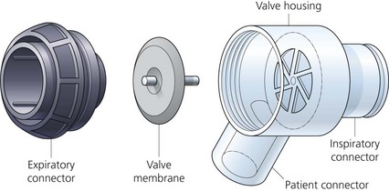
Fig. 8.14 An Ambu valve disassembled. (Reproduced with permission from AMBU International (UK) Ltd.)
2. The valve acts as a spillover valve allowing excess inspiratory gas to be channelled directly to the expiratory outlet, bypassing the patient port.
3. The valve is suitable for both IPPV and spontaneous ventilation.
4. The shape of the self-inflating bag is automatically restored after compression. This allows fresh gas to be drawn from the reservoir.
5. A paediatric version exists with a smaller inflating bag and a pressure relief valve.
6. Disposable designs for both the adult and paediatric versions exist.
PEEP valve
It is a spring-loaded unidirectional valve positioned on the expiratory side of the ventilator breathing system with a standard 22-mm connector. By adjusting the valve knob, a PEEP of between zero and 20 cm H2O can be achieved (Fig. 8.15).
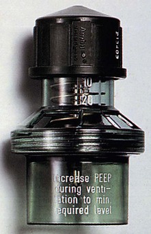
Fig. 8.15 The Ambu PEEP valve.
The valve provides almost constant expiratory resistance over a very wide range of flow rates.
Bersten A.D. Mechanical ventilation. In Bersten A., Soni N., Oh T.E., eds.: Oh’s intensive care manual, fifth ed, Edinburgh: Butterworth-Heinemann, 2003.
Merck. Overview of mechanical ventilation. Online. Available at http://www.merckmanuals.com/professional/critical_care_medicine/respiratory_failure_and_mechanical_ventilation/overview_of_mechanical_ventilation.html, 2007.
MHRA. Medical device alert: all Oxylog 3000 emergency/transport ventilators manufactured by Draeger (MDA/2010/092). Online. Available at http://www.mhra.gov.uk/Publications/Safetywarnings/MedicalDeviceAlerts/CON100176, 2010.
In the following lists, which of the following statements (a) to (e) are true?
a) The FGF is the driving gas at the same time.
b) Is a minute volume divider.
c) The bellows can be either ascending or descending.
d) With a leak, the ascending bellows may continue to move almost normally.
a) Is a minute volume divider.
c) During controlled ventilation, it is safe to activate the emergency oxygen flush device of the anaesthetic machine.
d) A pressure-monitoring ventilator alarm is attached to the expiratory limb.
e) It acts as a Mapleson D system during spontaneous ventilation mode.
a) It is a time-cycled ventilator.
b) There is some mixing of the fresh gas and driving gas.
c) For safety reasons, the descending bellows design is preferred.
e) The driving gas volume in the chamber equals the tidal volume.
4. Regarding classification of ventilators:
a) A pressure generator ventilator can compensate for changes in lung compliance.
b) A flow generator ventilator cannot compensate for leaks in the system.
c) A time-cycling ventilator is affected by the lung compliance.
d) The duration of inspiration in a pressure-cycling ventilator is not affected by the compliance of the lungs.
e) A pressure generator ventilator can compensate, to a degree, for leaks in the system.
a) False. The driving gas is separate from the FGF. The driving gas is usually either oxygen or, more economically, air. There is no mixing between the driving gas and the FGF. The volume of the driving gas reaching the chamber is equal to the tidal volume.
b) False. The tidal volume and respiratory rate can be adjusted separately in a bag in bottle ventilator.
c) True. Most of the bag in bottle ventilators use ascending bellows. This adds to the safety of the system as the bellows will collapse if there is a leak.
e) False. The ventilator can be used for both adults and children. A different size bellows can be used for different age groups.
a) True. The tidal volume can be set in a Manley ventilator. The whole FGF (minute volume) is delivered to the patient according to the set tidal volume, thus dividing the minute volume.
b) False. There are two sets of bellows in a Manley ventilator, the time-cycling bellows and the main bellows.
c) False. As it is a minute volume divider and the FGF is the driving gas (see a) above), activating the emergency oxygen flush will lead to considerable increase in the minute volume.
d) False. The pressure-monitoring alarm should be attached to the inspiratory limb and not the expiratory limb. A Wright spirometer can be attached to the expiratory limb to measure the tidal volume.
e) True. During the spontaneous (manual) breathing mode, the Manley ventilator acts as a Mapleson D system.
a) True. The inspiratory and expiratory periods can be determined by adjusting the I : E ratio and the respiratory rate. So, for example, with a rate of 10 breaths/min and an I : E ratio of 1 : 2, each breath lasts for 6 seconds with an inspiration of 2 seconds and expiration of 4 seconds.
b) False. There is no mixing between the fresh gas and the driving gas as they are completely separate.
c) False. In case of a leak in the system, the descending bellows will not collapse. The opposite occurs with the ascending bellows.
d) True. A PEEP of 2–4 cm H2O is expected due to the compliance of the bellows.
4. Regarding classification of ventilators:
a) False. A pressure generator ventilator cannot compensate for changes in lung compliance. It cycles when the set pressure has been reached. This can be a larger or smaller tidal volume depending on the lung compliance.
b) True. It will deliver the set flow whether there is a leak or not.
c) False. The ventilator will cycle with time regardless of the compliance.
d) False. In a lung with low compliance, the inspiration will be shorter because the pressure will be reached more quickly leading the ventilator to cycle and vice versa.
e) True. The ventilator will continue to deliver gases, despite the leak, until a preset pressure has been reached.
5. High-frequency jet ventilation:
a) False. The ventilator uses the Venturi principle to entrain ambient air. The amount of entrainment is uncertain, making the measurement of the FiO2 difficult.
b) False. Frequencies of up to 500/min (not Hz; i.e. per second) can be achieved with a high-frequency jet ventilator.
c) True. Because of the lower intrathoracic pressures generated during high-frequency jet ventilation, causing a lesser effect on the venous return, the cardiac output is better maintained.
d) True. It can be used both in anaesthesia and intensive care, e.g. in the management of bronchopleural fistula.
e) False. Although the risk is reduced, there is still a risk of barotrauma.
[/level-membership-for-anesthesiology-category][not-level-membership-for-anesthesiology-category]
Ventilators
Classification of ventilators
There are many ways of classifying ventilators (Table 8.1).
1. The method of cycling is used to change over from inspiration to exhalation and vice versa:
a) volume cycling: when the predetermined tidal volume is reached during inspiration, the ventilator changes to exhalation
b) time cycling: when the predetermined inspiratory duration is reached, the ventilator changes to exhalation. The cycling is not affected by the compliance of the patient’s lungs. Time cycling is the most commonly used method
c) pressure cycling: when the predetermined pressure is reached during inspiration, the ventilator changes over to exhalation. The duration needed to achieve the critical pressure depends on the compliance of the lungs. The stiffer the lungs are, the quicker the pressure is achieved and vice versa. The ventilator delivers a different tidal volume if compliance or resistance changes
d) flow cycling: when the predetermined flow is reached during inspiration, the ventilator changes over to exhalation. This method is used in older design ventilators.
2. Inspiratory phase gas control:
3. Source of power – can be electric or pneumatic.
4. Suitability for use in theatre and/or intensive care.
5. Suitability for paediatric practice.
6. Method of operation (pattern of gas flow during inspiration):
a) pressure generator: the ventilator produces inspiration by generating a constant and predetermined pressure. Bellows or a moderate weight produce the pressure. The inspiratory flow changes with changes in lung compliance (Table 8.2)
b) flow generator: the ventilator produces inspiration by delivering a predetermined flow of gas. A piston, heavy weight or compressed gas produce the flow. The flow remains unchanged by changes in lung compliance, although pressures will change (see Table 8.2). These ventilators have a high internal resistance to protect the patient from high working pressures.
7. Sophistication: new ventilators can function in many of the above modes. They have other modes, e.g. SIMV, PS and CPAP (see pp 224–225).
a) minute volume dividers: fresh gas flow (FGF) powers the ventilator. The minute volume equals the FGF divided into preset tidal volumes thus determining the frequency
b) bag squeezers replace the hand ventilation of a Mapleson D or circle system. They need an external source of power
c) lightweight portable: powered by compressed gas and consists of the control unit and patient valve.
Characteristics of the ideal ventilator
1. The ventilator should be simple, portable, robust and economical to purchase and use. If compressed gas is used to drive the ventilator, a significant wastage of the compressed gas is expected. Some ventilators use a Venturi to drive the bellows, to reduce the use of compressed oxygen.
2. It should be versatile and supply tidal volumes up to 1500 mL with a respiratory rate of up to 60/min and variable I : E ratio. It can be used with different breathing systems. It can deliver any gas or vapour mixture. The addition of positive end expiratory pressure (PEEP) should be possible.
3. It should monitor the airway pressure, inspired and exhaled minute and tidal volume, respiratory rate and inspired oxygen concentration.
4. There should be facilities to provide humidification. Drugs can be nebulized through it.
5. Disconnection, high airway pressure and power failure alarms should be present.
6. There should be the facility to provide other ventilatory modes, e.g. SIMV, CPAP and pressure support.
Manley MP3 ventilator
This is a minute volume divider (time cycled, pressure generator). All the FGF (the minute volume) is delivered to the patient divided into readily set tidal volumes (Fig. 8.1).
Components
1. Rubber tubing delivers the FGF from the anaesthetic machine to the ventilator.
2. Two sets of bellows. A smaller time-cycling bellows receives the FGF directly from the gas source and then empties into the main bellows.
3. Three unidirectional valves.
4. An adjustable pressure limiting (APL) valve with tubing and a reservoir bag used during spontaneous or manually controlled ventilation.
5. The ventilator has a pressure gauge (up to 100 cm H2O), inspiratory time dial, tidal volume adjuster (up to 1000 mL), two knobs to change the mode of ventilation from and to controlled and spontaneous (or manually controlled) ventilation. The inflation pressure is adjusted by sliding the weight to an appropriate position along its rail. The expiratory block is easily removed for autoclaving.
Mechanism of action
1. The FGF drives the ventilator.
2. During inspiration, the smaller bellows receives the FGF, while the main bellows delivers its contents to the patient. The inspiratory time dial controls the extent of filling of the smaller bellows before it empties into the main bellows.
3. During expiration, the smaller bellows delivers its contents to the main bellows until the predetermined tidal volume is reached to start inspiration again.
4. Using the ventilator in the spontaneous (manual) ventilation mode changes it to a Mapleson D breathing system.
Problems in practice and safety features
1. The ventilator ceases to cycle and function when the FGF is disconnected. This allows rapid detection of gas supply failure.
2. Ventilating patients with poor pulmonary compliance is not easily achieved.
3. It generates back pressure in the back bar as it cycles.
4. The emergency oxygen flush in the anaesthetic machine should not be activated while ventilating a patient with the Manley.
Penlon Anaesthesia Nuffield Ventilator Series 200
This is an intermittent blower ventilator. It is small, compact, versatile and easy to use with patients of different sizes, ages and lung compliances. It can be used with different breathing systems (Fig. 8.2). It is a volume-preset, time-cycled, flow generator in adult use. In paediatric use, it is a pressure-preset, time-cycled, flow generator.
Fig. 8.2 The Penlon Nuffield 200 ventilator. (Courtesy of Penlon Ltd, Abingdon, UK (www.penlon.com).)
Components
1. The control module, consisting of an airway pressure gauge (cm H2O), inspiratory and expiratory time dials (seconds), inspiratory flow rate dial (L/s) and an on/off switch. Underneath the control module there are connections for the driving gas supply and the valve block. Tubing connects the valve block to the airway pressure gauge.
2. The valve block has three ports:
a) a port for tubing to connect to the breathing system reservoir bag mount
b) an exhaust port which can be connected to the scavenging system
3. The valve block can be changed to a paediatric (Newton) valve.
Mechanism of action
1. The ventilator is powered by a driving gas independent from the FGF. The commonly used driving gas is oxygen (at about 400 kPa) supplied from the compressed oxygen outlets on the anaesthetic machine. The driving gas should not reach the patient as it dilutes the FGF, lightening the depth of anaesthesia.
2. It can be used with different breathing systems such as Bain, Humphrey ADE, T-piece and the circle. In the Bain and circle systems, the reservoir bag is replaced by the tubing delivering the driving gas from the ventilator. The APL valve of the breathing system must be fully closed during ventilation.
3. The inspiratory and expiratory times can be adjusted to the desired I/E ratio. Adjusting the inspiratory time and inspiratory flow rate controls determines the tidal volume. The inflation pressure is adjusted by the inspiratory flow rate control.
4. With its standard valve, the ventilator acts as a time-cycled flow generator to deliver a minimal tidal volume of 50 mL. When the valve is changed to a paediatric (Newton) valve, the ventilator changes to a time-cycled pressure generator capable of delivering tidal volumes between 10 and 300 mL. This makes it capable of ventilating premature babies and neonates. It is recommended that the Newton valve is used for children of less than 20 kg body weight.
Bag in bottle ventilator
Modern anaesthetic machines often incorporate a bag in bottle ventilator.
Components
1. A driving unit consisting of:
a) a chamber (Fig. 8.3) with a tidal volume range of 0–1500 mL (a paediatric version with a range of 0–400 mL exists)
2. A control unit with a variety of controls, displays and alarms: the tidal volume, respiratory rate (6–40/min), I/E ratio, airway pressure and power supply (Figs 8.3 and 8.4).
Mechanism of action
1. It is a time-cycled ventilator.
2. Compressed air is used as the driving gas (Fig. 8.5). On entering the chamber, the compressed air forces the bellows down, delivering the fresh gas to the patient (the fresh gas is accommodated in the bellows).
3. The driving gas and the fresh gas remain separate.
4. The volume of the driving gas reaching the chamber is equal to the tidal volume.
Problems in practice and safety features
1. Positive pressure in the standing bellows causes a PEEP of 2–4 cm H2O.
2. The ascending bellows collapses to an empty position and remains stationary in cases of disconnection or leak.
3. The descending bellows hangs down to a fully expanded position in a case of disconnection and may continue to move almost normally in a case of leakage.
