Chapter 10 Ventilation in the intensive care unit
Ideal requirements
• the ability to ventilate all sizes of patient from neonate to obese adults. However, specific machines have been designed to ventilate neonates and most ICU ventilators are designed only to have the ability to ventilate small infants to large adults
• operational versatility with the ability to provide different patterns of ventilation for varied clinical circumstances. The machines should offer the ability to alter such characteristics as inflation pressure, tidal volume, gas flow, respiratory rate and inspiratory to expiratory (I/E) ratio
• a facility for the patient to breathe spontaneously through the ventilator in spontaneously breathing mode without imposing an increased work of breathing
• the ability to augment patient efforts in spontaneous breathing modes to prevent respiratory muscle fatigue
• the ability to increase the pressure in the inspiratory limb of the patient circuit for the application of positive end expiratory pressure (PEEP) and continuous positive airway pressure (CPAP) in spontaneous breathing modes
• the ability to deliver a preset volume with flow characteristics independent of changes in a patient’s lung resistance and compliance
• the ability to cope with large leaks from the patient circuit without altering performance: essential for non-invasive ventilation via masks or hoods
• the delivery of precise inspired oxygen concentrations varying from 21 to 100% in all ventilatory modes
• the ability to humidify inspired gasses without changing ventilator characteristics
• the ability to add drugs or additional gasses such as helium and to nebulize bronchodilators into the inspiratory limb without altering the ventilator performance or inhaled oxygen concentration
• accurate and reliable monitoring of patient and ventilator respiratory performance along with alarms should these exceed predefined limits
• patient safety features such as high pressure relief valves and gas supply safety features in the event of either electrical, gas supply or control system failure
• easy to use and intuitive operator controls
• the ability to ensure that patients are not exposed to cross infection hazards by using disposable or easily sterilised patient circuits and expiratory valves
• the ability to work independently of mains electrical or pipeline gas supply to facilitate patient transport
• reliable component parts with infrequent routine maintenance schedules.
Differences between ventilators for anaesthesia and intensive care
Ventilators used in anaesthesia were primarily designed to replace the minute ventilation of a patient with healthy lungs who is paralyzed or has a depressed respiratory drive as a result of anaesthetic agents and opiates.1 In contrast intensive-care patients are normally encouraged to breathe alongside the mechanical ventilatory support which is gradually reduced during a slow weaning phase. Additionally at the end of anaesthesia, extubation is more precipitous with the rapid recovery of consciousness and return of spontaneous breathing. ICU ventilators, therefore, have to cope with the complexity of both machine- and patient-initiated respiration.
Driving mechanisms
All ventilators require a driving force to deliver a gas flow into the patient. This force may either deliver the inspiratory gas directly to the patient or indirectly by compressing a bag or bellows containing the inspired gas mixture which in turn delivers the gasses to the patient.2 Driving mechanisms which have been used in ventilators include the following:
1. Rotating electric motors. These may be used to:
2. Linear electric motors. These can be used to drive either pistons or diaphragms which are used in high frequency oscillators.
3. Tension springs which compress the gas in a storage bellows prior to being delivered to the patient. The disadvantage of this mechanism is that the pressure in the bellows is not constant but varies with the tension in the springs.
4. Weighted bellows. The gravitational force on a mass (the weight) will produce a constant driving pressure within the bellows; however, this mechanism is very susceptible to movement.
Microprocessor electronic control
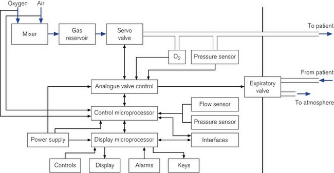
Some ICU ventilators use dual microprocessors to control the ventilator function. The advantage of using two processors in parallel is that not only can the function of information display be separated from the control of the valves, but each microprocessor can check the output of the other against its own computations to ensure maximum patient safety and ventilator reliability (Fig. 10.1).
Information display
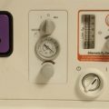
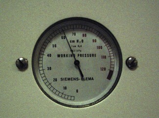
In the oldest ICU ventilators, the only information available to the operator was the analogue measurements of pressure or volumes (Fig. 10.2). With the same starting point of pressure measurement, microprocessor integration of the data now allows any number of derived variables to be monitored and displayed to inform the clinician of machine function and pulmonary mechanics. Alarm parameters can then be set for many of these values.
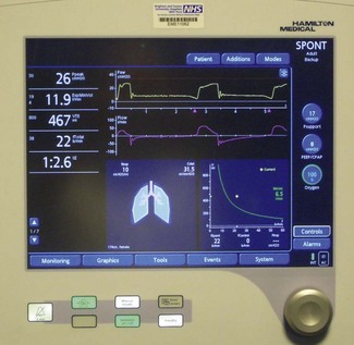
Digital information such as pressure values (peak, plateau, PEEP, etc.), calculations of tidal volume, machine or patient triggered breaths, inspired/expired volume differences and the quantity of gas leaking from the patient circuit were available to the user originally only in single-line numeric format (Fig. 10.3).3 With the availability of liquid crystal display (LCD) screens, more of this information, instead of being provided in single numeric displays, is available on a matrix screen, allowing the user not only to see the static numerical data, but also graphical information, such as flow, pressure and volume variations. These may be plotted in parallel against time or as loops against one another. The increasing use of graphical displays allows the user to more easily understand the effect that a change in ventilator controls has on the delivery of gas to the patient. Although LCD screens have the advantage of low-power consumption, they are only readable over a narrow viewing angle and are in turn now being replaced by TFT LCD (thin film transistor LCD) screens that can provide similar information in colour. These are readable over a larger viewing angle and in lower lighting conditions (Fig. 10.4).

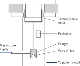
Inspiratory flow valve
High-speed proportional servo controlled (see below) flow valves are used in several manufacturers’ ventilators. They are capable of delivering flows from 20 to 3000 ml s−1 and are adjusted by the ventilator’s microprocessor control (servo control) using an electrodynamic motor similar to that of a loudspeaker. A current flowing in the field coils of the solenoid generates the force to move the piston up and down; connected to the piston is the valve orifice which opens to allow gas to flow. This type of valve has a quick response time of typically 5 ms and with the small internal dead space of the ventilator, the flow rates change almost immediately in the patient circuit allowing precise control of the desired flow pattern and tidal volume. The microprocessor monitors the position of the valve and the pressure drop across it to enable it to continually adjust the flow to the required setting so that its performance characteristics are not affected by back pressure in the circuit (Fig. 10.5).
Some manufacturers use high-pressure, high-speed on-off gas solenoids, which control the flow of both oxygen and air. Under the microprocessor’s control these can be rapidly pulsed on and off to create the desired inspiratory flow pattern. Ventilators using these types of inspiratory solenoid no longer require a separate gas blender to create the oxygen air mixture as this is produced directly by the solenoids from the high-pressure gas pipeline. Not having a separate gas blender and mixing chamber allows the ventilator to rapidly change oxygen concentration within the patient circuit in response to altered settings by the operator, facilitating a swift 100% oxygen setting for use prior to tracheobronchial suctioning.
Flow sensors
Flows sensors (see Chapter 2, Measurement of pressure and gas flow) are often placed in both the inspiratory and expiratory limbs of ventilators. These not only allow the ventilator microprocessor control to sense and adjust gas flow, but also provide the user with measurements of inspiratory and expiratory tidal volumes, whether ventilator delivered or patient initiated.
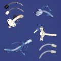
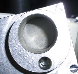
Manufacturers have used a variety of flow sensors. These can be either a wire mesh pneumotachograph as incorporated into ventilators such as the Siemens 900C (Fig. 10.6) or a hot wire anemometer, as used in the expiratory limb of the Dräger Evita ventilators (Fig. 10.7) or the bidirectional variable orifice device that is incorporated into the patient end of the ventilator circuit in the Hamilton G5 ventilators (Fig. 10.8). The Maquet Servo-i uses an ultrasonic flow transducer (see Chapter 2). Flow sensors placed in the expiratory limb are susceptible to condensation hence some manufacturers incorporate a heating arrangement to ensure that these devices are kept free of water droplets.
Patient triggering
To facilitate the patient’s spontaneous ventilation alongside mechanically driven breaths in such modes as intermittent mandatory ventilation and pressure support (see below), ICU ventilators have to be able to sense the commencement of the patient’s own respiratory efforts and then provide a gas source from which they can breathe. This can be achieved by sensing a change in either flow or pressure within the circuit, triggering the ventilator to open the inspiratory valve. If the patient has to generate large changes of pressure within the circuit before obtaining any inspiratory gas supply this will add significantly to their work of breathing. Together with the increased pressure changes, a time delay from the commencement of the patient’s inspiratory effort to the start of gas flow will multiply the effect of any pressure drop; further increasing in the patient’s work of breathing.4
Pressure triggering
Early ventilators such as the Siemens Servo 900C provided only pressure triggering; the pressure-sensing device being placed upstream within the inspiratory limb inside the ventilator. The pressure drop resulting from the patient’s inspiratory effort activates the trigger whose sensitivity is usually set to −1–2 cm H2O. When the threshold is reached, the electronic control within the ventilator opens the inspiratory valve allowing sufficient gas to reach the patient.5 The disadvantage of this method of sensing is that due to the remote placement of the sensor the patient may have to generate a considerably greater effort at the patient end of the circuit to activate the trigger threshold within the ventilator. This was particularly apparent when thin-walled, highly compliant, disposable plastic tubing was connected to the ventilator. In addition if a hot water humidifier is also connected in the inspiratory limb, the added compliance and resistance of this further increases both the pressure gradient and the patient’s work of breathing before obtaining any inspiratory gas supply.6
Flow triggering
To overcome the disadvantages of pressure triggering most ICU ventilators now provide a form of flow triggering.7 A flow trigger does not directly require change in pressure within the inspiratory circuit to enable a patient-initiated breath. The ventilators provide a continuous bias flow, frequently 10 l min−1, which is introduced into the inspiratory circuit throughout all phases of the machine’s respiratory cycle. When the patient starts to initiate a breath from the circuit, the fall in bias flow in the expiratory limb of the ventilator is sensed and the ventilator opens the inspiratory valve to allow a patient-initiated breath. The change in flow required to trigger a patient breath can be adjusted by the operator and is often set between 1 l min−1 and half the bias flow.8 The advantage of this mode is that it is not as affected by humidifiers in the inspiratory limb or condensation in the tubing so patient work of breathing is minimized.6,9,10 Most ventilators allow the user to adjust the sensitivity of the flow triggering to achieve the minimum work of breathing without the occurrence of falsely triggered breaths.11
Expiratory pressure generation
• Fixed pressures can be generated by a spring-loaded valve, an underwater column or a weighted valve leaflet. The latter two types’ function is severely impaired with movement and no longer used. It is worth noting that these types of valves exert a resistance throughout exhalation as a result of the mechanical force of the spring. Electronically controlled valves are usually only activated when the desired PEEP level is reached and do not impede exhalation until this point.
• Variable pressure valves have the advantage that they can be controlled (electronically) by the operator to produce the desired level of expiratory pressure and they can be closed completely by the ventilator to function as the expiratory valve as well.
Exhalation valves
Constriction type (scissor valves)
PEEP/CPAP can be produced using a variable orifice device in which the pinching of the expiratory rubber exit tube by an electromagnetic scissor valve can be used to control expiratory flow and pressure. During inspiration these valves can be closed completely to allow gas to flow into the patient’s lungs (Fig. 10.9).
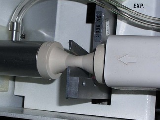
Diaphragm type – mechanically operated
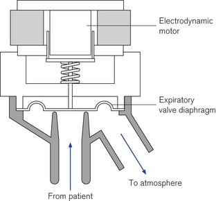
Levels of PEEP/CPAP can be generated using a linear electrodynamic motor that operates a large surface silicon membrane. Electrical current supplied to the motor during exhalation will produce a force on the diaphragm that is proportional to the level of PEEP/CPAP required. During inspiration the silicon diaphragm is forced hard onto the expiratory valve seat by the action of the actuator rod (Fig. 10.10). In normal exhalation the weight of the actuator shaft is balanced by a internal spring so the patient only has to overcome the weight of the membrane to exhale (Fig. 10.11); the expiratory resistance in this type of valve is less than 2 cm H2O/L/s.12
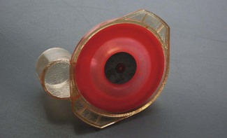
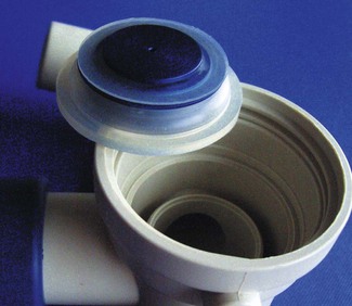
Diaphragm type – pressure operated
The force on the expiratory valve diaphragm can be generated pneumatically within the ventilator in a similar fashion to that of the inspiratory gas flow, although from a single gas sources as it does not need to be a blend of air and oxygen. When this gas is applied to the non-patient side of the expiratory valve diaphragm it can be used to control the level of PEEP/CPAP in the ventilator circuit. The diaphragms used in these types of expiratory valve have a larger central mass (Fig. 10.12), to provide the required damping to prevent inadvertent oscillations.
Overpressure valves
To ensure patients are not subjected to excessive airway pressures, ventilators provide protection in the form of an electronically controlled pressure limiter with a secondary mechanical device as back-up. The electronically controlled pressure limit can be set by the operator and this will prevent pressure rising within the circuit even if the desired tidal volume is not delivered. Audible and visual alarms are triggered in any overpressure condition.
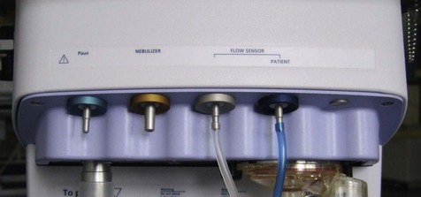
Nebulizer port
Ventilator manufacturers provide an additional gas source to drive a micro-nebulizer for the delivery of drug into the patient circuit (Fig. 10.13). The advantage of these fixed outlets is that this driving gas contains the same preset oxygen concentration as the respiratory gas, but it can be made to only be operational during the inspiratory phase so the drug is not wasted by being blown down the expiratory limb of the ventilator circuit. Unlike separate external gas flows these will not interfere with the ventilators’ flow triggering sensitivity.
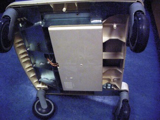
Battery back-up
Additional batteries can be provided to allow for more prolonged periods of disconnection from mains electrical supply to facilitate the movement of patients; these batteries are often stored in the base of the ventilator stand (Fig. 10.14). The addition of cylinder supplies of oxygen and air will allow the machine to be used as a transport ventilator.
Flow pattern generation/ventilation modes
With the use of sophisticated microprocessors and high-performance pneumatic controls, the gas flow characteristics of such ventilators are no longer primarily determined by the physical characteristics of the machines, as had been the case with anaesthesia ventilators in the past.
A classification for mechanical ventilators proposed three types of variables:13
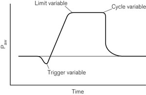
1. Control variables, which included pressure, volume, flow and rate
2. Phase variables, which defined how the change over points in the respiratory cycle occur, these being trigger, cycle and limit variables (Fig. 10.15)
3. Conditional variables, which define additional parameters, such as supplementary breaths and sighs.
Control and phase variables
Pressure pre-set control mode
In this mode, often referred to as pressure-controlled ventilation (PCV), a predefined inspiratory pressure is applied to the airways and the resulting pressure difference between the ventilator and the alveolus results in inflation until there is equilibrium between the two; after a pre-set inspiratory time, passive exhalation follows. In this mode the delivered volume during respiration is dependent on pulmonary and thoracic compliance. A potential disadvantage of this mode is that changes in pulmonary mechanics will result in varying tidal volumes and minute ventilation.14 With accurate flow sensors within the circuit, close monitoring of tidal ventilation is employed and dramatic changes in tidal volume or minute ventilation will trigger a warning alarm.
As this mode of ventilation pre-sets the pressures within the inspiratory circuit, the flow pattern cannot be greatly influenced by the user, and is usually of a falling flow pattern type as the pressure gradient between the inspiratory circuit and the alveolus declines with lung inflation. This usually results in a more homogenous gas distribution throughout the lung and improved arterial blood oxygenation and may reduce the patient’s work of breathing compared to volume pre-set modes during assisted modes of ventilation.15
Other ventilator modes
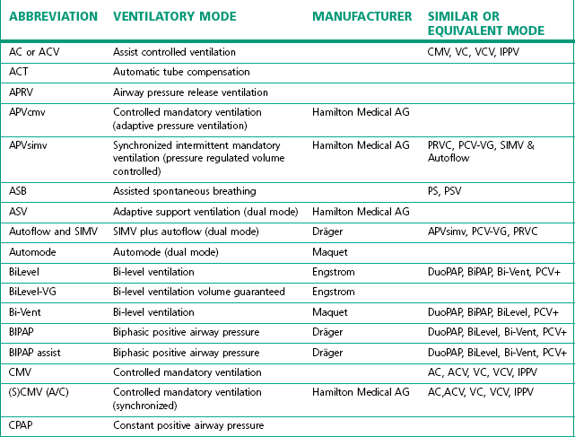
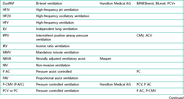
The degree of sophistication of the new generation of ventilators has spawned an increase in the variety of and scope for ventilation strategies. This has led to an impressive increase in terminology to describe these. Unlike the nomenclature for drugs, there is no international standardization of the names attached to different modes of ventilation, even when they use similar control and phase variables throughout the respiratory cycle. Manufacturers have contributed to this confusion by using patents or trademarks to prevent similar names being used on other companies’ machines (Table 10.1).
Conditional variables
Intermittent mandatory ventilation (IMV)
In this mode breaths are delivered from the ventilator at pre-set intervals. However, patient’s spontaneous respiration is allowed between ventilator-administered breaths.16 The IMV rate may be reduced allowing increased time for the patient’s spontaneous respiration during the weaning process.
Synchronous intermittent mandatory ventilation (SIMV)
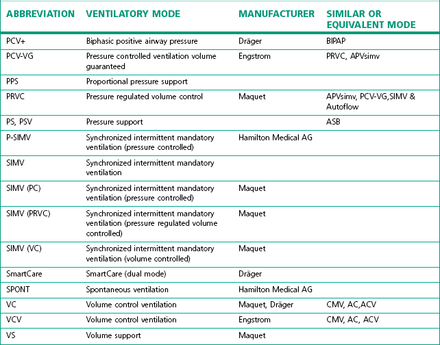
In this mode the ventilator tries to deliver its breaths in conjunction with the respiratory effort of the patient. Spontaneous breathing is also allowed between ventilator-administered breaths (Fig. 10.16).
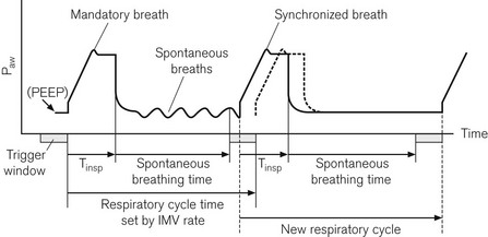
Figure 10.16 Synchronization of IMV breaths. The second tidal volume (synchronized breath) is delivered early because an inspiratory effort falls within the trigger window. The machine’s next respiratory cycle timing is reset from this point.
On its own the SIMV mode has not been shown to improve patients’ weaning from ventilatory support.17 This may be due to the increased work of breathing associated with spontaneous respiration through these mechanical circuits. The work is created by having to generate sufficient pressures and flows within the ventilator tubing to trigger the opening of the ventilator’s inspiratory valve for access to the extra gas flow required.
Pressure support mode/spontaneous assist
Pressure support (PS) ventilation has been shown to decrease the work of spontaneous breathing through ventilator circuits.18,19 When triggered to do so, the ventilator produces a pressure in the respiratory circuit to support the patient’s own inspiratory effort. The respiratory effort is detected either by flow or pressure triggering. With this mode of ventilation a user pre-set pressure is generated in the circuit (not a fixed tidal volume) to assist every patient spontaneous effort. This predefined airway pressure is sustained until the patient’s own inspiratory flow falls below a predefined cut off, e.g. 25% of peak inspiratory flow20 (Fig. 10.17). The disadvantage of this mode of ventilation is that if the patient fails to take any respiratory effort, no pressure supported breaths will be initiated. To avoid the potentially disastrous consequences most ventilators have a back-up apnoeic SIMV rate should the patient’s spontaneous respiration cease.
Figure 10.17 Pressure and flow curves when expiration trigger in pressure support mode is set to 25% of peak inspiratory flow.
For patients who have adequate respiratory drive and whose respiratory failure is not severe, PS ventilation may offer the patient considerable advantages, as all the breaths are patient initiated and breath stacking and fighting the ventilator are almost abolished. Even patients who are initially tachypnoeic, may be successful managed in this mode as the supporting pressure can be set sufficiently high to augment their own tidal volume and hence, reduce patient respiratory rate. As this is a pressure pre-set mode of ventilatory support, the risks of barotrauma associated with high airway pressures and fixed tidal volume ventilation are reduced.21
For patients who have severe respiratory failure this mode of ventilation is commonly used in conjunction with volume pre-set or pressure pre-set SIMV modes.22
Traditional ‘control modes’ of ventilation have only allowed the patient to breathe during the ventilator’s expiratory phase. Most modern machines now provide a pressure preset control mode of ventilation that will allow the patient to breathe during any point of the ventilator respiratory cycle; although similar in function this mode is called by several names including BiLevel, Bi-Vent, BIPAP and DuoPAP.
Closed loop controlled ventilatory modes
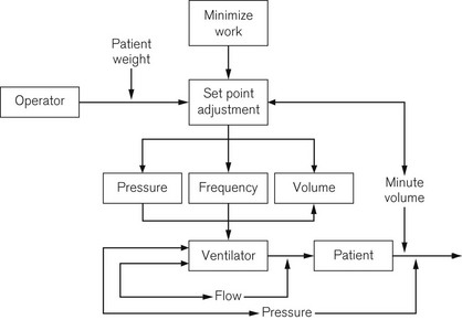
The ability of ventilators to automatically wean clinically stable patients off ventilatory support has long been the aim of many manufacturers. Early ventilator models adjusted either tidal volume or inspiratory pressure to achieve a target end tidal carbon dioxide level. However, in intensive care patients, end tidal carbon dioxide does not always correlate with arterial carbon dioxide tension and the target variable of minute ventilation is more often used instead. Most ventilator manufacturers provide a closed loop mode of control implementing different versions of mandatory minute ventilation (MMV) (see Table 10.2) in which the target of minute ventilation is achieved by the ventilator adjusting inspiratory pressure and frequency.23 Later versions of MMV have incorporated algorithms (Fig. 10.18) that aim to reduce the patient’s work of breathing while still achieving the desired minute ventilation by encouraging the patient to breathe with larger tidal volumes and slower rates, this being more efficient than rapid shallow breathing.24
Table 10.2 Closed loop controlled ventilatory modes
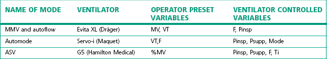
F, rate; VT, tidal volume; MV, minute volume; Pinsp, inspiratory pressure level; Psupp, pressure support level; Ti, Inspiratory time; MMV, mandatory minute ventilation; ASV, adaptive support ventilation
Dual control mode
Newer modes of ventilation referred to as dual control are where the ventilator acting in a closed loop feedback fashion measures parameters during the delivery of the breath and adapts its output in response to these changes according to a predefined algorithm.3 These adaptations can be accomplished within a single breath when the ventilator changes from a pressure to a volume control mode. More commonly dual control breath-to-breath is used by ventilator manufacture to allow incremental changes to occur to achieve the desired outcome.
Adaptive support ventilation (ASV)
ASV is based on algorithm using the Otis equation25 designed to minimize the patient’s work of breathing by targeting tidal volume and respiratory rate. This dual mode works in either a pressure controlled or a pressure support mode, switching between the two modes depending on the patient’s own respiratory activity.
Automatic tube compensation (ATC)
Ventilator manufacturers have tried to produce other additional modes for spontaneously breathing patients which attempt to reduce the resistance inherent with gas flows through an endotracheal tube. With the aim of keeping the pressure in the trachea at the desired level the ventilator adjusts inspiratory pressure according to the gas flow and direction.26
Individual ventilators
900C
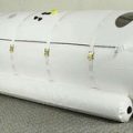
The Siemens 900C ceased production in 2004 but is still in use and supported by the manufacturer. It has essentially two parts (Fig. 10.19): a pneumatic section sitting on top, and an electronic section below containing the ventilator controls and electronic displays. The two sections are connected by a cable and could be separated if desired. High-pressure gas enters the pneumatic section from an external blender. A second gas inlet connection is provided that accepts low pressure directly from an anaesthetic machine, if required. The gas then passes through an oxygen analyzer and main bacterial filter before entering a spring-loaded bellows, which stores the gas prior to use.
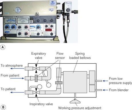
Figure 10.19 A. Servo 900C series ventilator. B. Servo 900C working principles: diagram of the pneumatic section (see text).
From the bellows, gas passes through the inspiratory flow transducer and then through the inspiratory scissor valve before leaving the unit to enter the patient circuit. Exhaled gas returning from the patient via the expiratory limb of the patient circuit re-enters the ventilator and passes through the expiratory flow transducer and expiratory scissor valve before exiting the unit via a one-way valve to the atmosphere. The inspiratory scissor valve consists of a flexible piece of silicone rubber tubing that is compressed in the jaws of a scissor mechanism using an electric stepper motor to control gas flow. In contrast, the compression of the equivalent tube in the expiratory scissors valve is controlled and varied by a pull of an electro-magnet under the control of the ventilator’s electronics. This force is adjusted to maintain the correct PEEP in the expiratory limb; during inspiration the valve remains shut.
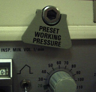
During inspiration, the gas flow is measured at the inspiratory flow transducer and compared in the electronics section to that which is required to achieve the operator’s preset volume. If the actual flow does not match the required value, the stepper motor varies the compression of the inspiratory scissors valve to adjust the flow delivery. The driving pressure for the gas flow is generated by the pre-set tension in the spring attached to the inspiratory bellows, and during high inspiratory flow rates this may be insufficient to deliver the required gas flow. In this situation, the working pressure will have to be increased manually by the turning the key on the front of the pneumatic section (Fig. 10.20).
Servo-i and Servo 300
The Servo-i (Fig. 10.21A) and its predecessor the Servo 300 (last manufactured in 2003) has two units: a patient pneumatic unit and the control unit connected by a cable. The electronic circuit of the control unit both controls and displays the ventilator settings used to operate the pneumatic unit (Fig. 10.21B). Oxygen and air are supplied by pipeline and are blended directly into the patient’s circuit by high-speed gas solenoid valves; unlike their predecessor (the 900C) there is no bellows storage for inspiratory gas and no low-pressure port for the supply of anaesthetic gas.
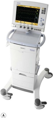
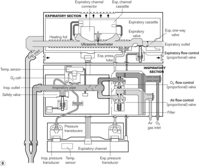
Figure 10.21 A. Servo-i. B. Working principles showing inspiratory section and detachable expiratory cassette.
Images courtesy of Maquet Critical Care.
The solenoid valves have a response time of 6 ms under microprocessor control and can be rapidly opened or closed to achieve the desired flow rate and pattern in the ventilator circuit. In the Servo 300, the exhaled gas from the patient returns to the unit and passes through the expiratory flow transducer and pressure controlled expiratory valve before exiting out to the atmosphere. The Servo-i has a detachable expiratory cassette containing the entire expiratory gas flow pathway, together with the ultrasonic expiratory flow transducers and the expiratory valve. The expiratory pressure sensor and the actuator for the valve are housed in the body of the ventilator. The expiratory cassette can be autoclaved and the pressure sensor is protected by a bacterial filter.
Dräger Evita series (2 Dura, 4, XL)
Dräger Evita 4 and XL series of ventilators have three sections; the electronic compartment, which sits directly on top of the pneumatic controls, and a third detachable display unit, which houses the controls and touch-sensitive screen (Fig. 10.22A). The screen displays both the ventilator information and the virtual touch sensitive buttons and dials. The 2 Dura model combines the display and the electronic and pneumatics in a single case.
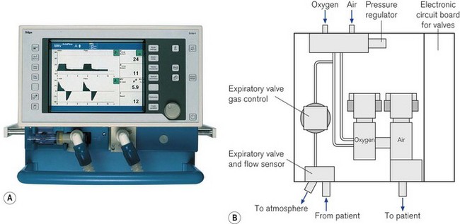
Pneumatics (Fig 10.22B)
Gas from the high-pressure pipelines enters the ventilator via a filter and a non-return valve directly into the two proportional valves that control the flow of oxygen and air to be blended directly into the patient circuit. Sensors measure the pressure of the oxygen and air supplied to the ventilator and with this information a central microprocessor is able to adjust the function of the valves to deliver the correct flow into the patient circuit producing the inspiratory breath. The returning expiratory gas leaves the ventilator via a diaphragmatically operated expiratory valve and then through the external hot wire flow sensor finally to atmosphere. The PEEP/CPAP pressure is controlled by a balancing pressure from a separate proportional valve using the regulated oxygen supply applied to the downstream side of the expiratory diaphragm (see also Fig. 4.29). The gas flow of 9 l min−1 required to drive the nebulizer (when used) is also obtained from this oxygen supply. Here, the main two pneumatic valves are automatically re-adjusted to deliver the correct oxygen concentration.27 During an oxygen pipeline failure, a switch-over valve is operated that allows the pneumatics to continue to function normally using the pressure from the air supply.
Non-invasive ventilation
The application of mechanical ventilatory support through a mask or helmet in place of endotracheal intubation is becoming increasingly accepted and utilized in the ICU. This modality of ventilatory support can be used successfully for patients with mild-to-moderate respiratory failure, but the patient must be mentally alert enough to follow commands, as without an endotracheal tube there is no mechanical method of preventing aspiration into the lungs. Clinical situations in which it has proven useful include acute exacerbation of chronic obstructive pulmonary disease (COPD) or asthma, and decompensated congestive heart failure (CHF) with mild-to-moderate pulmonary oedema. Conventional ICU ventilators set in their PSV mode of ventilation with PEEP are commonly use to support non-invasive ventilation through a mask,4 although specially designed machines are now available for use in general acute wards (Fig. 10.23). Conventional ICU ventilators have the advantage of sophisticated monitoring and precise control of the oxygen concentration and inspiratory flow pattern, but set in their normal ventilatory modes they are ill adapted to cope with the large leaks of gas that may occur with poorly fitting masks and awake patients.28 Manufacturers now often provide non-invasive modes on standard ICU ventilators that are more tolerant of the gas leakage from the patient circuit.
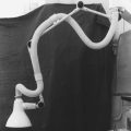
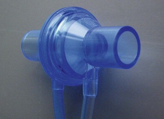
Specialist non-invasive machines use an electrically driven blower (Fig. 10.24) to deliver the inspiratory gas supply and are capable of generating flows of 300 L min−1.29 The rotating speed of the electrical blower is adjusted by the ventilator’s microprocessor to achieve the operator’s desired level of pressure for both inspiration and expiration. This bi-level pressure ventilatory mode is time cycled in a similar manner to the CMV mode on conventional ICU ventilator, the only difference being that patient is capable of breathing during the ventilator’s inspiratory and expiratory cycle, as gas is supplied continuously during both phases of respiration. There is no expiratory valve in this type of ventilator, the gas leaving the system through a series of holes or slits close to the patient mask (Fig. 10.25A and B). Alterations in inspired oxygen concentration are achieved by entraining oxygen into the suction side of the blower or adding the oxygen flow directly into the patient circuit just before the mask; as a result it is difficult to achieve high inspired concentrations, particularly when the ventilation is delivering its maximum flow rate.
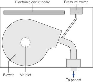
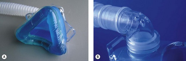
Figure 10.25 A. Mask for non invasive ventilation. B. Expiratory holes on mask mount for non-invasive ventilation.
With the addition of a pneumotachograph in the inspiratory limb, by sensing changes of 40 ml s−1 in the flow required to maintain the expiratory pressure, sophisticated non-invasive ventilators enable the patient to trigger the commencement of the inspiratory positive airway pressure. Large and variable leaks from the mask make the detection of patient expiration by flow triggering difficult and, hence, less comfortable for the patient than a time cycled expiratory trigger.30
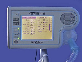
In the newer models of non-invasive ventilators manufacturers have incorporated pressure sensors and TFT matrix screens enabling the graphic display of pressure waveforms (Respironics BiPAP Vision). In addition, the fitting of oxygen sensors into the flow pathway allows more precise control of FIO2 and the ability to display the measured value on the screen.
High frequency oscillators
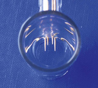
High frequency oscillators such as the SensorMedics 3100B or the Novalung Vision Alpha (Fig. 10.26A) use a device similar to a loudspeaker as the driving mechanism. The diaphragm (Fig. 10.26B) is made to operate at frequencies of 3–15 Hz or 180–900 breaths per minute, although typical starting settings are in the range of 5–6 Hz for adults.
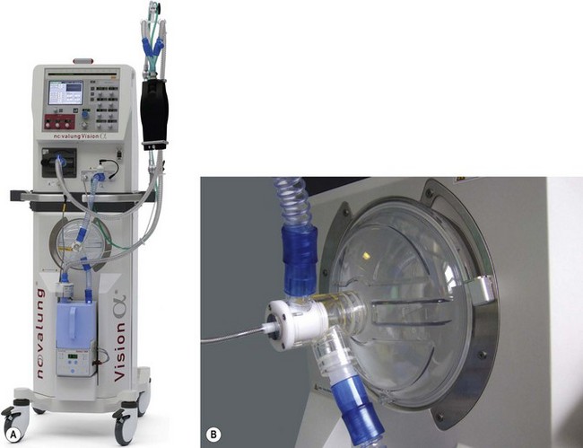
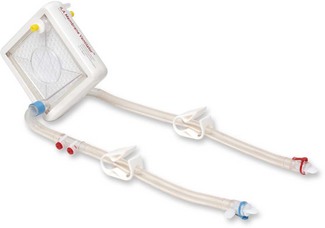
A fresh gas supply or bias flow is provided constantly down the inspiratory limb independent of the diaphragmatic oscillations and can be controlled by the operator in a range of 20–60 L min−1 (Fig. 10.27). Altering the power setting (sometimes referred to as delta P) increases the amplitude of the diaphragmatic oscillations. Carbon dioxide elimination from the patient is achieved by a combination of altering the power setting or increasing the bias flow.31 The inspiratory proportion of the total time can also be adjusted by the operator. Alternatively the CO2 removal may be largely accomplished by extrapulmonary means using simple, pumpless, miniature extracorporeal circuits (termed ‘interventional lung assist’ devices) (Fig. 10.28), allowing even greater degrees of lung rest.32,33
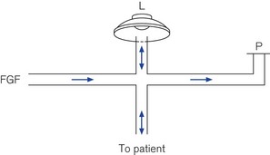
Figure 10.27 Schematic of high frequency oscillator ventilator. FGF, fresh gas flow; L, oscillator; P, PEEP valve.
The Vision Alpha can also be used as a conventional ventilator in a CMV or CPAP mode. Humidification of patient gasses is achieved by a conventional-type water bath arrangement (the blue single-use patient canister can be seen in Fig. 10.26A) and to prevent rain out, the spiral anti-kink bindings of the patient circuit are embedded throughout with a heating wire. Low compliance 15 mm diameter tubing is used.
1 Del Valle RM, Hecker RB. A review of ventilatory modalities used in the intensive care unit. Am J Anesthesiol. 1995;22:23–30.
2 Smallwood RW. Ventilators – reported classifications and their usefulness. Anaesth Intensive Care. 1986;14:251–257.
3 Chatburn RL. Computer control of mechanical ventilation. Respir Care. 2004;49:507–517.
4 Nava S, Ambrosino N, Bruschi C, Confalonieri M, Rampulla C. Physiological effects of flow and pressure triggering during non-invasive mechanical ventilation in patients with chronic obstructive pulmonary disease. Thorax. 1997;52:249–254.
5 Sassoon CS, Gruer SE. Characteristics of the ventilator pressure- and flow-trigger variables. Intensive Care Med. 1995;21:159–168.
6 Street MK, Hopkinson RB. Evaluation of the comfort of spontaneous respiration through three ventilator systems. Intensive Care Med. 1987;13:405–410.
7 Prinianakis G, Kondili E, Georgopoulos D. Effects of the flow waveform method of triggering and cycling on patient-ventilator interaction during pressure support. Intensive Care Med. 2003;29:1950–1959.
8 Sassoon CS. Mechanical ventilator design and function: the trigger variable. Respir Care. 1992;37:1056–1069.
9 Giuliani R, Mascia L, Recchia F, Caracciolo A, Fiore T, Ranieri VM. Patient-ventilator interaction during synchronized intermittent mandatory ventilation. Effects of flow triggering. Am J Respir Crit Care Med. 1995;151:1–9.
10 Ranieri VM, Mascia L, Petruzzelli V, Bruno F, Brienza A, Giuliani R. Inspiratory effort and measurement of dynamic intrinsic PEEP in COPD patients: effects of ventilator triggering systems. Intensive Care Med. 1995;21:896–903.
11 Imanaka H, Nishimura M, Takeuchi M, Kimball WR, Yahagi N, Kumon K. Autotriggering caused by cardiogenic oscillation during flow-triggered mechanical ventilation. Crit Care Med. 2000;28:402–407.
12 Techical Specification. Veolar operators manual. Rhazuns: Hamilton Medical; 1992.
13 Chatburn RL. Classification of mechanical ventilators. Respir Care. 1992;37:1009–1025.
14 Kallet RH, Alonso JA, Diaz M, Campbell AR, Mackersie RC, Katz JA. The effects of tidal volume demand on work of breathing during simulated lung-protective ventilation. Respir Care. 2002;47:898–909.
15 Kallet RH, Campbell AR, Alonso JA, Morabito DJ, Mackersie RC. The effects of pressure control versus volume control assisted ventilation on patient work of breathing in acute lung injury and acute respiratory distress syndrome. Respir Care. 2000;45:1085–1096.
16 Sassoon CS. Intermittant mandatory ventilation. In: Tobin MJ, ed. Principles and practice of mechanical ventilation. New York: McGraw-Hill; 1994:221–237.
17 Brochard L, Rauss A, Benito S, Conti G, Mancebo J, Rekik N, et al. Comparison of three methods of gradual withdrawal from ventilatory support during weaning from mechanical ventilation. Am J Respir Crit Care Med. 1994;150:896–903.
18 Brochard L, Harf A, Lorino H, Lemaire F. Inspiratory pressure support prevents diaphragmatic fatigue during weaning from mechanical ventilation. Am Rev Respir Dis. 1989;139:513–521.
19 Esteban A, Frutos F, Tobin MJ, Alía I, Solsona JF, Valverdú I. A comparison of four methods of weaning patients from mechanical ventilation. Spanish Lung Failure Collaborative Group. NEJM. 1995;332:345–350.
20 Du HL, Amato MB, Yamada Y. Automation of expiratory trigger sensitivity in pressure support ventilation. Respir Care Clin N Am. 2001;7:503–517. x
21 Moylan FM, Walker AM, Kramer SS, Todres ID, Shannon DC. The relationship of bronchopulmonary dysplasia to the occurrence of alveolar rupture during positive pressure ventilation. Crit Care Med. 1978;6:140–142.
22 Esteban A, Anzueto A, Alia I, Gordo F, Apezteguía C, Pálizas F, et al. How is mechanical ventilation employed in the intensive care unit? An international utilization review. Am J Respir Crit Care Med. 2000;161:1450–1458.
23 Brunner JX. Principles and history of closed-loop controlled ventilation. Respir Care Clin N Am. 2001;7:341–362. vii
24 Brunner JX, Iotti GA. Adaptive Support Ventilation (ASV). Crit Care Med. 2002;68:365–368.
25 Otis AB, Fenn WO, Rahn H. Mechanics of breathing in man. J Appl Physiol. 1950;2:592–607.
26 Guttman J, Erbhard L, Fabry B, Bertschmann W, Wolff G. Continuous calculation of intratracheal pressure in tracheal intubated patients. Anesthesiology. 1993;79:503–513.
27 Service Manual Evita 4, 5th ed. Lubeck, Dräger Medizintechnik GmbH, 2000.
28 Mehta S, McCool FD, Hill NS. Leak compensation in positive pressure ventilators: a lung model study. Eur Respir J. 2001;17:259–267.
29 BiPAP Vision: Respironics, 2003.
30 Calderini E, Confalonieri M, Puccio PG, Francavilla N, Stella L, Gregoretti C. Patient-ventilator asynchrony during noninvasive ventilation: the role of expiratory trigger. Intensive Care Med. 1999;25:662–667.
31 Fort P, Farmer C, Westerman J, Johannigman J, Beninati W, Dolan S, et al. High-frequency oscillatory ventilation for adult respiratory distress syndrome – a pilot study. Crit Care Med. 1997;25:937–947.
32 David M, Heinrichs W. High-frequency oscillatory ventilation and an interventional lung assist device to treat hypoxaemia and hypercapnia. Br J Anaesth. 2004;93:582–586.
33 Lubnow M, Luchner A, Philipp A, Buchner S, Jeron A, Karagiannidis C, et al. Combination of high frequency oscillatory ventilation and interventional lung assist in severe acute respiratory distress syndrome. J Crit Care. 2010 Sept;3:436–444.