[level-membership-for-anesthesiology-category]
Chapter 3 Vaporizers
Laws of vaporization
Factors affecting vaporization of a liquid
Temperature
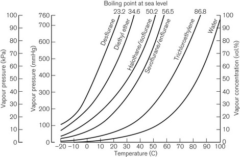
Vaporization is increased if the temperature of the liquid is raised, since more molecules will have been given sufficient kinetic energy to escape. Fig. 3.1 shows the vapour pressure curves of volatile anaesthetic agents (as well as water) and shows how they vary with temperature. If the liquid is heated, a point is reached at which vaporization now occurs not only at the surface of the liquid, but also in vapour bubbles that develop within its substance. The liquid is now boiling and this temperature is its boiling point. At this temperature, the SVP of the liquid is equal to the ambient atmospheric pressure.
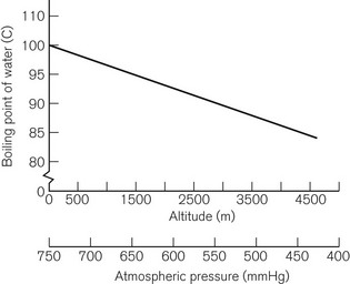
The boiling point of a liquid may therefore vary with atmospheric pressure. At high altitudes (where the air is thinner, has a lower ambient pressure and therefore exerts less pressure on the surface of a liquid) there is a significant depression of the boiling point. This may render the administration of agents with low boiling points, such as ether, difficult. Fig. 3.2 shows the depression of the boiling point for water with change in atmospheric pressure.
Volatility
The speed at which a liquid vaporizes depends not only on its ambient temperature and pressure, but also on its volatility. A more volatile liquid has weaker cohesive forces between its molecules, such that they require less energy (i.e. a lower temperature) to vaporize (Fig. 3.1). This is reflected in a higher SVP at any temperature and a lower boiling point.
Vaporizing systems
A modern vaporizer needs to be constructed so that it provides a suitable, stable and predictable concentration of anaesthetic vapour for admixture with other patient gasses. The delivered amount of vapour must not be affected by changes in temperature, and flow rates of other gasses.
Types of vaporizer
Appropriate vaporization may be achieved by either:
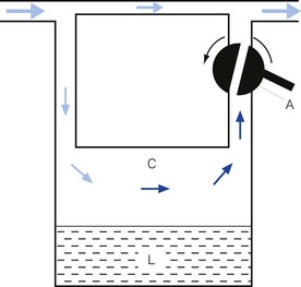
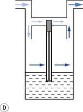
• splitting the patient gas flow so that only a portion passes through the vaporizer. This picks up saturated vapour and then leaves to mix with the remainder of the gas that has gone through a bypass. The final concentration may be altered by varying the splitting ratio between bypass gas flow and vaporizer gas flow, using an adjustable valve. This type is often referred to as a variable bypass vaporizer (Fig. 3.3); or
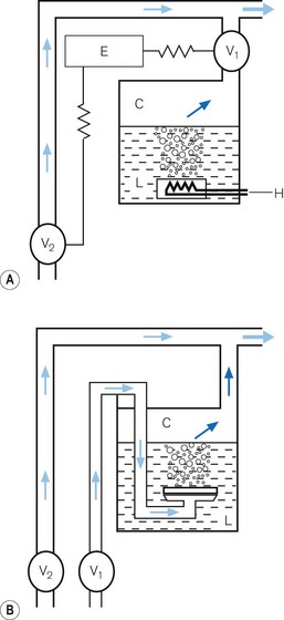
• alternatively, the vaporizer can be constructed so that it heats the anaesthetic agent to a temperature above its boiling point (in order that it may behave as a gas) and which can then be metered into the fresh gas flow (Fig. 3.4A). Similarly, a vaporizer may contain a fine metal sieve that is submerged in the anaesthetic agent and through which a small independent and metered gas supply (normally oxygen) can be made to pass. The minute bubbles produced have a very large surface area and produce a saturated vapour at ambient pressure, which can then be passed into the fresh gas flow (Fig. 3.4B). These types of vaporizer are often referred to as measured flow vaporizers.
It should also be noted that the various anaesthetic inhalational agents currently available have widely differing potencies and physical properties and hence require devices constructed specifically for each agent. Very potent agents (halothane, enflurane, sevoflurane, isoflurane and desflurane) require vaporizers that can accurately control the concentration of vapour leaving the vaporizer. However, agents such as diethyl ether, with a lower potency, may be used safely with simpler apparatus (if necessary), in which the vapour concentration is not accurately known, since there is less risk of over-dosage (see Chapter 27).
Variable bypass vaporizers
Design features
Surface area of contact between carrier gas and the liquid
Vaporizers, which are required to be very accurate, should always present a saturated vapour to the bypass gas across a wide range of flows. To ensure sufficient vaporization at the highest planned flow, a sufficiently large surface area of liquid should be present. This size is also governed by the volatility of the agent used. A highly volatile liquid will require a smaller surface area. The surface area for vaporization of a liquid can be increased by causing it to spread (by capillarity) over a large sheet of porous material which may be folded in such a way that the carrier gas passes across its entire surface (Fig. 3.5).
Temperature
In order to maintain the expected output of the vaporizer when this occurs, a greater proportion of carrier gas is required to pass through the vaporizing chamber in order to collect sufficient vapour molecules. This is achieved by using devices that are sensitive to changes in temperature (temperature-compensating devices, Fig. 3.6) and which then increase the flow through the vaporizing chamber.
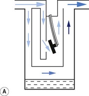
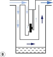
1. The first (Figs 3.6A and B) consists of two dissimilar metals or alloys placed back to back (i.e. a bi-metallic strip). As the two metals have different rates of expansion and contraction with temperature, the device has the ability to ‘bend’. It can, therefore, be used to vary the degree of occlusion in the aperture of a gas channel (usually the bypass) and thus alter the flow of carrier gasses through it.
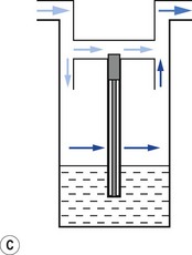
2. In the second arrangement (Figs 3.6C and D), the bi-metallic device consists of a central rod made of Invar, a metal alloy with a low coefficient of expansion, sitting inside a brass jacket, the top part of which is attached to the roof of the vaporizing chamber. The rod is attached only at the base of the brass jacket, which has a higher coefficient of expansion. The outer surface of the jacket is immersed in liquid anaesthetic agent in the vaporizing chamber. As the aforementioned liquid cools, the brass jacket contracts more than the Invar, which is pushed upwards into the bypass, restricting the flow of bypass gas and increasing the flow of carrier gas through the vaporizing chamber.
Potency of anaesthetic agent
As described above, current anaesthetic vapours are too potent to be administered as saturated vapours and require suitable dilution. Therefore, only a proportion of the gas intended for the patient is diverted in the vaporizer to collect vapour. This amount may be varied to produce the desired concentration by using an adjustable flow-splitting valve (see Fig. 3.3). This is usually a rotary valve incorporated within the vaporizer outlet. It proportions the flow of gas between the vaporizing chamber and the vaporizer bypass system, thus controlling the final vapour composition (i.e. the more gas going through the vaporizer chamber, the greater the amount of vapour leaving the vaporizer). The flow-splitting valve is calibrated in percentage of the vapour in the final gas/vapour composition. However, this valve is accurate only if the vaporizer is temperature-compensated (see above). As both the temperature-compensating mechanism and the flow-splitting valve work by altering resistance through the vaporizer, the devices are dependent on each other. Therefore, each vaporizer for a designated anaesthetic agent is individually calibrated at the factory (see below) for that agent and for a specific range of temperatures and flow rates of carrier gas.
Volatility
The flow-splitting ratio is dependant on the volatility of the agent. For example, at any given temperature, a very volatile agent will produce a higher saturated vapour pressure than a less volatile agent, even though they may have similar potencies. The former, however, requires a flow-splitting valve with a wider ratio so as to increase the dilution in order to provide a similar concentration. Table 3.1 shows the relative potency and volatility of some liquid anaesthetic agents that influence vaporizer design.
Table 3.1 Relative potency and volatility of some liquid anaesthetic agents
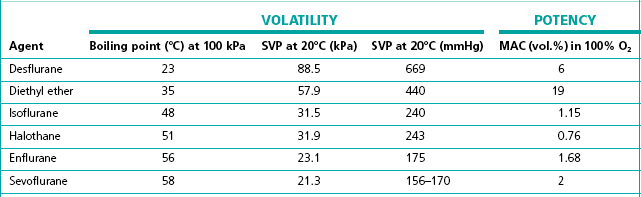
MAC, minimum alveolar concentration;
SVP, saturated vapour pressure
Types of variable bypass vaporizers
Draw-over vaporizers
The early vaporizers relied on the patient’s respiratory effort to draw gas over the vaporizing surface (hence their name). Unfortunately, draw-over systems are subjected to very variable flow rates, i.e. from 0 to 601 min−1 (the peak inspiratory flow in a hyperventilating adult). At these higher flows the carrier gas may fail to pick up a saturated vapour resulting in a reduced concentration leaving the vaporizer. Furthermore, the gas pathways must offer little resistance to flow so as not to compromise the patient’s inspiratory effort. This restricts the design of the vaporizer components, especially the flow-splitting valve (see above), which must have sufficiently wide a bore. It is very difficult to design a flow-splitting valve that will work accurately over a wide range of flow rates, i.e. 1–60 l min−1. As discussed above, the valve must present a low flow resistance so that at flows of 40 l min−1 (the peak flow in a patient breathing spontaneously), no respiratory embarrassment is caused. However, if the flow across this valve drops to about 4 l min−1, the resistance through the valve will be so low that carrier gas will preferentially pass across the bypass channel rather than through the vaporizing chamber where it has to mix with and then push the ‘heavy’ vapour out into the attached breathing system. At this flow and below, there is thus bound to be a marked fall in vaporizer performance.
Factors affecting vaporizer performance
Barometric pressure
Ideally, a vaporizer should also be calibrated at a specific barometric pressure. Strictly speaking, as a saturated vapour is only altered by temperature, one might expect the calibration of a vaporizer to be independent of barometric pressure. However, changes in barometric pressure will affect the carrier gas composition passing through the vaporizer, which in turn will affect the concentration of vapour in the mixture leaving it. For example, when the barometric pressure is reduced (at altitude), the number of molecules of carrier gas flowing through the vaporizer is reduced. However, the number of vapour molecules collected by the gas in the vaporizing chamber remains unchanged, although these now represent a higher percentage of the total number of molecules leaving the vaporizer. The final output concentration of vapour is thus now higher than at sea level, although its partial pressure remains unchanged. As anaesthetic effect is governed by the partial pressure of the agent in the body, there is no effective change under the normal conditions. However, extremes of pressure may have a significant effect. For example, at very high altitude (low barometric pressure), a very volatile liquid such as ether may boil at ambient temperature. This may render the use of such agents difficult. Fig. 3.2 shows the variation of boiling point with atmospheric pressure.
Pumping effect
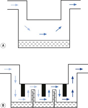
When a resistance is applied to the outlet of the anaesthetic machine, such as that which occurs when manually assisted inspiration or controlled ventilation is used, there is an intermittent increase in the anaesthetic gas pressure, which is transmitted back to the vaporizer. When this happens, it causes carrier gas within the vaporizer to be compressed. Gas in the outlet is already saturated and, therefore, cannot pick up any more vapour. When the back pressure is released, the expanding carrier gas, which is also saturated with vapour, surges out through both the inlet and outlet of the vaporizer chamber. The gas that leaves the inlet enters the bypass and adds to the vaporizer output to increase in the final vapour output. (Fig. 3.7 demonstrates the sequence of events.)
• increasing the resistance to flow through the vaporizer and bypass so that the carrier gas develops a higher pressure within the vaporizer, so as to reduce the pumping effect. However, the pressure increase due to vaporizer design should be as small as possible as these pressures are transmitted back to the flowmeters, which are calibrated for use at near atmospheric pressure; or
• building an elongated flow passage into either the inlet or outlet of the vaporizer to minimize the effect of surges in pressure (Fig. 3.8).
Liquid levels
The liquid level within the vaporizing chamber may affect performance. If the vaporizer is overfilled, insufficient exposed surface area of wick may cause a drop in vapour output. Additionally, over-filling may result in dangerously high concentrations, due to spillage of liquid agent into the bypass.
Summary of vaporizer performance
Vaporizer performance can thus be affected by:
• Temperature (unless the vaporizer includes some compensatory device that minimizes the effect of temperature, such as a heat sink and/or temperature compensator)
• Flow. All vaporizers are affected to some degree by flow (performance data are usually available from the manufacturer). Plenum vaporizers perform better than draw-over vaporizers
• Barometric pressure (minimal clinical effect in practice)
• Variable vaporizer working pressures (back pressure surges)
• Liquid levels within the vaporizer
• Movement and tilting of vaporizers (see below, under Specific vaporizers)
Calibration of vaporizers
Vaporizers designed to give an accurate output are individually calibrated prior to leaving the factory. Typically, they are filled with the designated anaesthetic agent and left in a room at a standard temperature (23°C) for 4 hours. A blank control dial (linked to a computer) is attached and rotated at various carrier gas flow rates. The output concentration is measured using a sample that is analyzed by a refractometer (see Fig. 15.3). The dial (which has a unique serial number) is then removed and a calibration scale etched onto it from the information stored on the computer. It is then re-attached to that same vaporizer and the calibration confirmed prior to leaving the factory. Vaporizers may also have the calibration confirmed in a similar manner, following servicing.
Filling of vaporizers
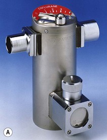
In the original plenum vaporizers, a screw-threaded stopper in the filling port was simply unscrewed, liquid agent was added and the stopper reconnected. These systems were criticized and have largely disappeared from use as the vaporizer could easily be filled with the wrong agent. Despite this, they are still supplied by all the major manufacturers for certain countries (Fig. 3.9) and are referred to as ‘screw fill’ systems.
Agent-specific filling devices (in the UK) (Fraser Sweatman pin safety system) were introduced by Cyprane (which became Ohmeda and is now part of GE Healthcare) in the early 1980s. In these the distal end was keyed to fit a vaporizer calibrated, labelled and colour coded for a specific agent and the proximal end keyed to fit only the neck of the bottle for that agent (Fig. 3.10A).
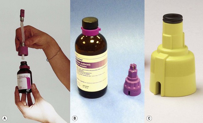
This is now referred to commonly as the ‘key fill’ system. Dräger have a similar system (Dräger-fil) for their Vapor range (Fig. 3.10B) as do GE Healthcare (Easy-Fil) (Fig. 3.10C).
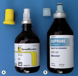
Although these devices go some way to reducing the potential for filling vaporizers with the wrong agent, it is by no means foolproof. For example it would still be possible to decant one agent from an open bottle to another agent-specific one. Some manufacturers of sevoflurane (Abbott) and desflurane (Baxter) produce sealed bottles to which the agent-specific filling device is already fitted and made tamper-proof with a crimped metal seal. These filling devices also have valves, which are only opened when inserted fully into their respective filler ports, so as to prevent spillage (Figs 3.11A and B). The filling system for sevoflurane and the older agents can be designated at ordering of the vaporizer but sevoflurane from Abott Laboratories only uses their own, Quik-Fil system (Fig. 3.11A). The desflurane system (Fig. 3.11B) is called Saf-T-Fil (Baxter Healthcare) and operates across all vaporizer manufacturers.
Examples of variable bypass vaporizers
Temperature-compensated vaporizers
TEC 5 (GE Healthcare)
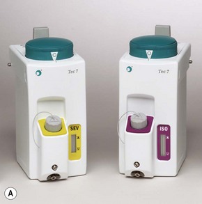
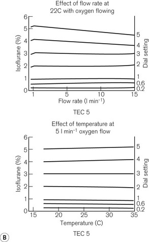
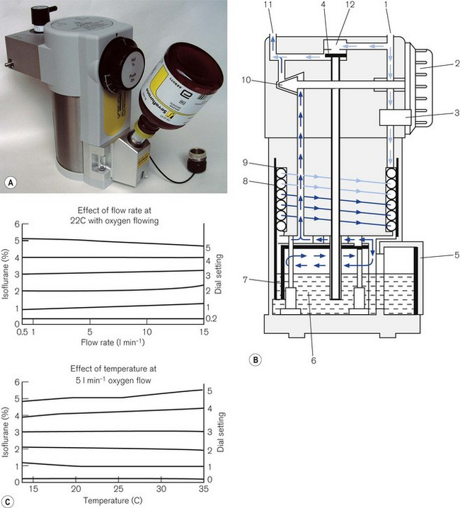
Fig. 3.12 shows a TEC 5 (with a keyed filler), its mode of operation and performance charts. Although now owned by GE Healthcare, these vaporizers and some TEC 7s (see below) are still badged as Datex–Ohmeda.
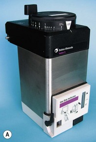
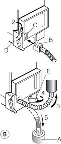
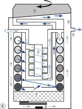
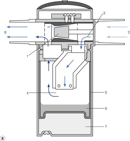
Figure 3.12 A. The TEC 5 vaporizer. B. Filling the vaporizer. (1) insertion of keyed filler B into vaporizer filling port C, (2) applying the lock D to make the filler/vaporizer connection secure, (3) inverting and raising the bottle of agent to create a filling pressure, (4) opening the chamber lock E to fill the chamber, (5) lowering the bottle below the vaporizer to empty the chamber if required. C. Working principles of Tec 5 and Tec 7 vaporizers. (1) inlet, (2) elongated passage that prevents ‘pumping effect’, (3) helical wick, (4) base of vaporizing chamber, (5) rotary valve for metering vapour saturated carrier gas, (6) mixing chamber, (7) bypass, (8) temperature-compensating device, (9) outlet.
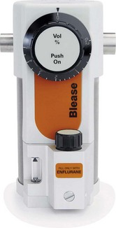
Blease Datum
This range fulfils all the criteria for a temperature compensated vaporizer. It has:
The earlier version had a very large heat sink made of brass, in order to reduce the cooling effect of vaporization: hence the vaporizer weighed 11 kg. The latest version (Fig. 3.14A) has an improved thermal conductivity and now weighs 7.5 kg. The earlier version had a stainless steel outer covering but this was separated from the brass body of the vaporizer by a layer of plastic. The latter has been removed to improve the absorption of radiant heat from the surroundings and has enabled less brass to be used. The heavy weight of the vaporizer helps to seat the vaporizer firmly on the back bar when it is connected to the anaesthetic workstation and so reduces the potential for leaks. The working principles of the vaporizer are shown in Figure 3.14B.
In the OFF position, there is a ‘zero lock’ (3) on the dial that isolates the vaporization chamber so that all the patient designated gas travels through the bypass. In the ON position this gas is split into two flows. One passes through the elongated wick (8), collecting vapour; the elongated passage behaves as a damping device to counteract the pumping effect. From here, the gas, which is now saturated with anaesthetic vapour, travels through to the vapour control valve (10), operated by the control dial (2). It then joins the remainder of the gas in the bypass. A thermal compensator (4) alters the flow through the bypass (12), to correct for changes in vapour production at lower temperatures. The bi-metallic device consists of a central rod made of Invar, a metal alloy with a low coefficient of expansion, part of which sits inside a brass jacket, the top part of which is attached to the roof of the vaporizing chamber. (see above: Temperature compensating devices: p. 44, and Fig. 3.6C and D).
Unlike the TEC vaporizers, the control dial may be turned on when it is not connected to a machine and so if this is left on and the vaporizer is inadvertently tipped, there is the potential for liquid anaesthetic agent to enter the bypass. However, the relevant channels are placed towards the front of the vaporization chamber near the filler block. If the vaporizer falls on its side, the filler block prevents these channels from being submerged in liquid agent. Figure 3.14C shows the performance curves for the vaporizer.
Dräger ‘Vapor’ 2000 series of vaporizers
Figures 3.15A, B and C show the vaporizer, working principles and performance curves. Models in the range are all compensated for temperature and pumping effects. In the OFF position, gasses destined for the patient are directed through the bypass (12) in the vaporizer without coming into contact with anaesthetic vapour.
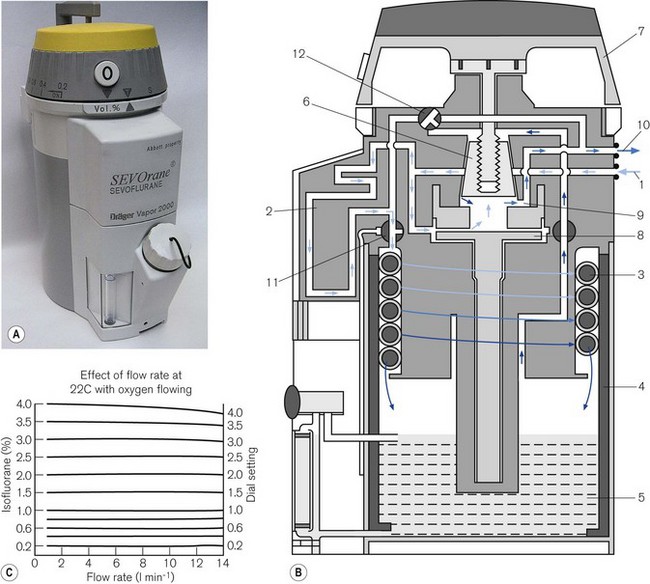
From the vaporizing chamber, the saturated gasses pass to a conical control valve (6), whose aperture is adjusted by the calibration dial (7). From here they pass to a mixing chamber (9), where they blend with bypass gasses prior to leaving the vaporizer. If the operating temperature of the latter drops, a compensating device (8) (see also Figs 3.6C and D) proportionately decreases the flow of gasses through the bypass so as to maintain the output of the vaporizer.
Penlon Sigma Delta vaporizer
The Penlon Sigma Delta, shown in Figs 3.16A and B, includes all the features of a modern Plenum vaporizer.
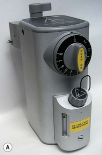
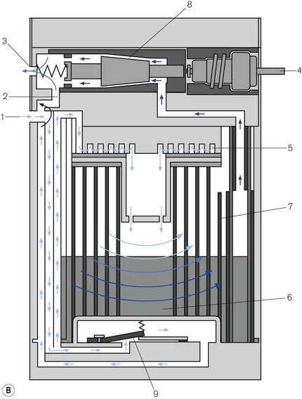
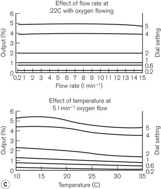
Figure 3.16 A. Penlon Sigma Delta vaporizer. B. Working principles: (1) inlet, (2) bypass, (3) outlet, (4) control knob, (5) helical damping coil, (6) vaporizing chamber, (7) wick, (8) needle valve, (9) temperature compensating element. C. Performance characteristics.
From here they pass into the vaporizing chamber (6) and around the wick (7). The latter is novel in that it is made of sintered polyethylene (1 m long), which is held in close proximity to a copper backing plate. The two are then coiled into a spiral, the top and bottom of which are made gas-tight. The carrier gasses, therefore, have to pass around the spiral, coming into contact with the whole surface area of the wick. The wick assembly is designed as a cartridge for ease of removal and cleaning, and has a long service life. The recommended service interval is 5 years for halothane vaporizers and 10 years for all others.
The vaporizer is interesting in that it is relatively light (5 kg), being made of aluminium. Aluminium has a better thermal conductivity than brass and so, despite its weight, it conducts a similar amount of radiant heat as does an equivalent sized brass device. The rotary control can be turned on when the vaporizer is disconnected from an anaesthetic workstation. If this occurs and the vaporizer is tipped on its side or inverted, then liquid vapour could enter the outflow from the vaporizing chamber.
Plenum vaporizers with electronic control
GE Healthcare – Aladin and Aladin 2 vaporizers
Both vaporizers function in a similar manner. The Aladin 2 has a few added refinements which will be described below. The Aladin range has a conventional vaporizing chamber in the form of a detachable cassette and an electronic vapour control unit built into the anaesthetic workstation (see also Chapter 4, Aisys and ADU).
The cassette
The cassette (Fig. 3.17A) is a leakproof metal box that is divided into two sections. The larger rear section is the vaporizing chamber which is filled with a synthetic material that behaves as a wick. It is formed into lamellae (1) interspersed with metal plates (2) to create a convoluted pathway, so as to maximize vapour pick-up. The back panel has inflow (3) and outflow (4) spring-loaded mechanical ball valves, to prevent a leak of agent when transported. There is also a mechanical contact for the temperature sensor (6) that is placed within the vaporizer to measure the temperature of the liquid. The front section of the unit has a handle (7) and a locking mechanism (8) for securing it to the workstation. There is a conventional vapour-specific filling system (9) with a clear glass window (larger in the Aladin 2) displaying the liquid level (10). The Aladin 2 has an additional liquid level sensor that feeds information back to the anaesthetic workstation via an electronic bus (5) which also conveys vaporizer temperature data. Capacitor plates that sense the level of agent, are fitted inside this device and the four copper contacts of the electronic bus, on the top of the unit, power the capacitor and transmit information. Agent level is then displayed graphically.
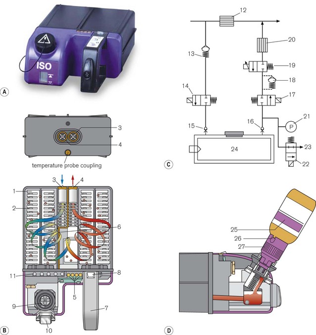
Figure 3.17 (A) Aladin 2 cassett. (B) Diagram of the back of the casette and cutaway showing carrier gas flow – (1) wicks, (2) lamellae, (3) inlet valve, (4) outlet valve, (5) contact for electronic temperature sensor and liquid anaesthetic agent level, (6) temperature sensor strip (7) handle, (8) locking mechanism, (9) fill system (10) liquid level window, (11) agent identification magnets (not visible externally). (C) Diagram of control unit- (12) bypass flow measurement, (13) one way valve, (14) inflow close valve, (15) inlet check valve, (16) outlet check valve, (17) outflow close valve, (18) liquid flow prevention, (19) proportional flow valve, (20) agent flow measurement, (21) cassette pressure sensor, (22) cassette pressure relief valve, (23) flow to scavenging, (24) Aladin cassette. (D) Filling the casette: (25) Colour coded bottle, (26) Colour coded adapter tab, (27) Colour coded adapter cap.
In the ADU workstation there is a fan that is activated when the desflurane cassette is fitted and that directs heat through vents from the workstation electronics onto the vaporizing chamber when this has cooled below a critical level. In the Aisys using the Aladin 2 desflurane cassette none of this is required (see Chapter 4).
The control unit
Housed in the anaesthetic workstation (Fig. 3.17B), this behaves as an electronic variable bypass. When the user sets an anaesthetic concentration on the front panel of the workstation, the fresh gas flow is split into two. The bulk of the gasses pass across the bypass where the flow is measured (12). A smaller portion of the gasses pass through a mechanical one way valve (13), through an electronic ‘inflow close valve’ (14), through the open ball valve (15) in the back of the cassette (that is opened when the cassette in plugged into the workstation) and into the vaporizing chamber. It picks up saturated vapour and leaves the cassette via the other open ball valve (16), an electronic ‘outflow close valve’ (17) and a liquid flow prevention valve (18) to the proportional flow valve (19) that controls vapour output. From here it passes to the agent flow measurement device (20) and into the outlet of the control unit, where it joins the bypass gas in a mixing chamber. The electronic inflow and outflow valves are open when the vaporizer is in use. Otherwise they remain closed to prevent a leak of gas destined for the patient when a cassette is not attached.
A microprocessor gathers information regarding the agent used, its temperature in the cassette and the flow of gas in the bypass. It makes a calculation for the amount of agent to add to the bypass gas to provide the desired concentration (set electronically by the user on the workstation display) and instructs the proportional flow valve to open sufficiently to provide this. The presence of a cassette, the specific agent, its level in the cassette and the calculated vapour concentration delivered are displayed electronically on the workstation screen (Aisys range). The outflow pathway from the cassette is fitted with an electronic pressure sensor (21). If the outflow pressure exceeds 2.5 bar, a relief valve opens (22) and vents the flow to scavenging (23).
Draw-over vaporizers
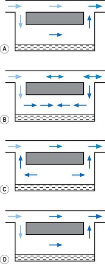
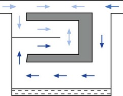
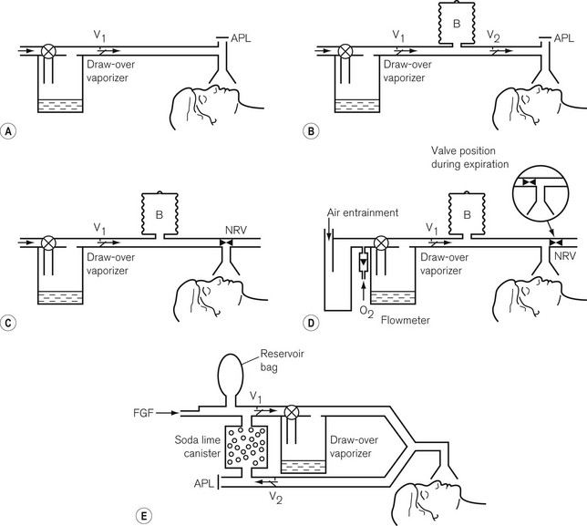
All the plenum vaporizers described above offer resistance to the gas flow. For this reason carrier gasses have to be pressurized to some degree to be driven through them. However, pressurized gas sources are not always available in some countries or in certain situations. Draw-over vaporizers, with their low-resistance gas pathways, can be installed within a breathing system and are therefore, a useful alternative to plenum systems despite not being as accurate. Fig. 3.18 illustrates various breathing systems in which a draw-over vaporizer has been installed. In systems A–D, exhaled gasses are vented to the atmosphere and suitably scavenged where appropriate. However, in system E, the patient’s exhaled gasses are recirculated through the vaporizer. This is of importance, since not only will the concentration of volatile agents be increased by the repeated passage of the gasses through the vaporizer, but the latter must be of a type without cloth wicks, since these could become saturated with water condensed from the expired air and so cease to function.
Typical examples of draw-over vaporizers are described below. Further examples may be found in Chapter 27.
The Oxford Miniature Vaporizer (OMV)
This vaporizer (Figs 3.19A and B) is primarily used with portable anaesthetic equipment with the armed forces and has the advantage that it may be drained of one anaesthetic agent and charged with another. Detachable scales are available for several agents. It is very simple to use and needs little in the way of servicing. It is still manufactured but is not marketed in the EU as it does not carry a kitemark.
It has a flow-splitting valve (1) that separates carrier gas (2) into bypass gas (3) and gas that passes through the vaporizer to pick up vapour (4). It has stainless steel wicks (5). It is not temperature compensated, but there is a sealed compartment (6), filled with water plus antifreeze, which acts as a heat sink to minimize changes of temperature. The ‘Triservice’ version is described in Chapter 27.
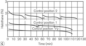
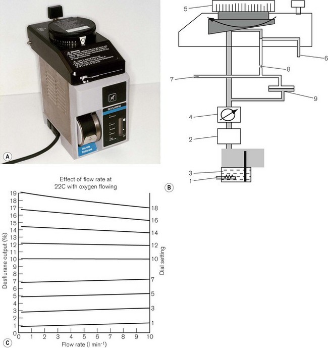
Epstein, Macintosh, Oxford (EMO) ether inhaler
This has been deservedly the most popular draw-over vaporizer (Fig. 3.20) for the administration of ether, and is still widely used throughout the world. For spontaneous respiration, it is often used in conjunction with the OMV (Oxford Miniature Vaporizer). The latter is usually filled with halothane to provide smooth and rapid induction of anaesthesia, which is then continued by ether from the EMO. Both vaporizers may be used in conjunction with self-inflating bellows for techniques employing controlled ventilation.
Measured flow vaporizers
TEC 6 (Plus) (Desflurane)
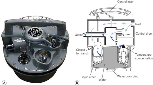
This vaporizer (Figs 3.21A and B) was designed specifically for the volatile agent desflurane. This agent is unusual in that its boiling point is around room temperature and so it would not remain as a liquid in the reservoir of a conventional vaporizer. It therefore requires an unusual design which dispenses with most of the conventional compensating devices mentioned above.
The vaporizer has a number of other features:
• The vaporizer heaters are switched on automatically when the unit is connected to the electricity supply. However, a 5–10 min warm-up time is required to reach operating temperature. During this time the concentration dial cannot be turned on.
• There are two more electric heaters in the upper part of the vaporizer to prevent vapour condensation.
• The concentration dial has graduations of 1%, but from 10–18% these are 2% increments. There is an interim stop at 12%, which can be manually overridden to access the higher concentrations.
• The front panel has five LED lights. From top to bottom they are labelled OPERATIONAL to indicate that the unit is ready to be used; NO OUTPUT for when the agent drops below minimum operating level; LOW AGENT to indicate that refilling is required; WARM UP (see below) and ALARM BATTERY LOW for when the back-up alarm power is either low or disconnected. The latter consists of a 9-volt alkaline battery which requires changing annually. The front panel also houses an LCD (liquid crystal display) of 20 vertically mounted bars that receives electronically processed signals from a sensor in the reservoir. The bars gradually disappear as the vaporizer empties, at which point the heaters are switched off and the low agent LED flashes. There are three symbols displayed on the side of the LCD. The uppermost (equivalent to all 20 bars showing), indicates that the reservoir is full (390 ml). In the middle, a mark indicates that a 240 ml refill is possible (a whole bottle) and the lowest indicates that the reservoir has only 60 ml left.
• At the beginning of the warm-up time, the vaporizer begins a self-testing sequence. The warning alarm sounds for 1 s and all the LEDs flash. When operating temperature is reached, the warm-up light (amber) extinguishes, the operational light glows (green) and the concentration dial unlocks.
• There is a detector which shuts off the vaporizer if it senses more than a 15° tilt off the vertical axis.
• The filler port accepts only the specific filler nozzle (SAF-T-FIl), which is crimped onto the supply bottle for desflurane. To fill the vaporizer, the filler nozzle is pushed into a spring-loaded aperture in the filler port, which is then rotated upwards by inverting the bottle. The contents of the bottle will then decant into the vaporizer reservoir. If the latter is filled only when the LCD bars fall below the 240 ml refill mark, then it will accept the whole bottle. When empty, the bottle may be returned to the starting position at which point the spring in the filler port will eject the filler nozzle. The filling process may be carried out even when the vaporizer is in use. As the bottle is pressurized, it is coated in plastic to prevent the glass splintering in the event of damage. Overfilling is prevented in normal circumstances by placing the outlet from the reservoir above the level attained by the bottle in its filling position. However, should the vaporizer be tilted (and this can only happen if the vaporizer is not in use and not attached to the back bar), overfilling can occur, although liquid will be prevented from leaving the reservoir by the shut-off valve. When the vaporizer is next commissioned, a small amount of liquid might leave the reservoir but would rapidly vaporize.
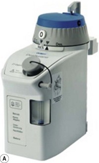
Dräger D Vapor
This vaporizer (Fig. 3.22) is another example of a measured flow vaporizer for desflurane and works on similar principles to the Tec 6 above. The agent is heated in a chamber so that it behaves as a gas. Its pressure is then regulated electronically to match the patient gas pressure as this alters with changes in flow rate. It is then fed into the gas stream via the calibrated control knob according to the desired concentration. It is fitted with the ubiquitous Saf-T-Fil connector for desflurane.
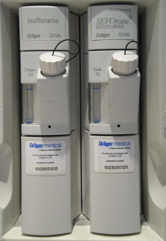
The Dräger DIVA
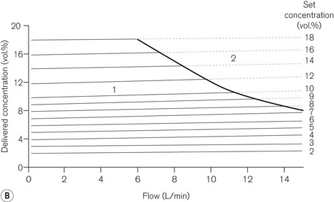
The DIVA (direct injection of volatile anaesthetic) anaesthetic vaporizer is yet another example of a measured flow vaporizer (Fig. 3.23). But unlike the examples above, it has two sections, a plug in vaporizing (and metering) module specific for a particular agent, and a built-in gas supply module that is built into the Dräger Zeus anaesthetic workstation and can accommodate two vaporizing modules.
Cole JR. The use of ventilators and vaporizer performance. Br J Anaesth. 1966;38:646–651.
Henegan CPH. Vapour output and gas driven ventilators. Br J Anaesth. 1986;58:932.
Loeb R, Santos B. Pumping effect in Ohmeda Tec 5 vaporizers. J Clin Monit. 1995;11:348.
Carter KB, Gray WM, Railton R, Richardson W. Long term performance of TEC vaporizers. Anaesthesia. 1988;43:1042–1046.
Gray WM. Dependence of the output of a halothane vaporizer on thymol concentration. Anaesthesia. 1988;43:1047–1049.
James MF, White JF. Anesthetic considerations at moderate altitude. Anesth Analg. 1984;63:1097–1105.
Jones CS. Gas viscosity effects in anesthesia. Anesth Analg. 1980;59:92–96.
Leigh JM. Variations on a theme splitting ratio. Anaesthesia. 1985;40:7072.
Loeb RG. The output of four modern vaporizers in the presence of helium. Can J Anaesth. 1992;39:888–891.
Palayiwa E, Hahn CEW, Sugg BR. Nitrous oxide solubility in halothane and its effect on the output of vaporizers. Anaesthesia. 1985;40:415–419.
Palayiwa E, Sanderson MH, Hahn CE. Effects of carrier gas composition on the output of six anaesthetic vaporizers. Br J Anaesth. 1983;55:1025–1038.
Schaefer HG, Farman IV. Anaesthetic vapour concentrations in the EMO system. Anaesthesia. 1984;39:171–180.
Scott DM. Performance of BOC Ohmeda Tec 3 and Tec 4 vaporisers following tipping. Anaesth Intensive Care. 1991;19:441–443.
White DC. Symposium on anaesthetic equipment. Vaporization and vaporizers. Br J Anaesth. 1985;57:658–671. (Review)
Wright D, Brosnan S, Royston B, White D. Controlled ventilation using isoflurane with an in-circle vaporiser. Anaesthesia. 1998;53:650–653.
Richardson W, Carter KB. Evaluation of keyed fillers on TEC vaporizers. Br J Anaesth. 1986;58:353–356.
Sato T, Oda M, Kurashiki T. A new agent-specific filling device for anesthetic vaporizers. Anesthesiology. 1988;68:957–959.
Uncles DR, Conway NE. Key issues in vaporizer filling. Can J Anaesth. 1994;41:878–879.
Wittmann PH, Wittmann FW, Connor J, Connor T. A new keyed vaporizer filler. Anaesthesia. 1994;49:710–712.
Blease Datum User and Maintenance Manual. Issue 2, December 1999.
Dräger Vapor 2000 Instructions for Use, 10th edn. August 2003.
Graham S. The desflurane Tec 6 vaporizer. Br J Anaesth. 1994;72:470–473.
Hendrick JF, De Cooman S, Deloof T, Vandeput D, Coddens J, De Wolf AM. The ADU vaporizing unit: a new vaporizer. Anesth Analg. 2001;93:391–395.
The TEC 6 Operation and Maintenance Manual. Datex Ohmeda English Language Issue 7, March 1994.
The TEC 5 Continuous Flow Vaporizer Operation and Maintenance Manual, Datex Ohmeda Issue 1, November 1989.
Penlon Sigma Elite User Instruction Manual Penlon Ltd. February 2001.
Baker AB. Low flow and closed circuits. Anaesth Intensive Care. 1994;22:341–342.
Brosnan S, Royston B, White D. Isoflurane concentrations using uncompensated vaporisers within circle systems. Anaesthesia. 1998;53:560–564.
Cartwright DP, Freeman MF. Vaporisers (editorial). Anaesthesia. 1999;54:519–520.
Kharasch ED, Subbarao GN, Cromack KR, Stephens DA, Saltarelli MD. Sevoflurane formulation water content influences degradation by Lewis acids in vaporizers. Anesth Analg. 2009;108:1796–1802.
MRHA Medical Device Alert. Overfilling of Vaporisers 31, Nov 2003.
Munson WM. Cardiac arrest: hazard of tipping a vaporiser. Anesthesiology. 1965;26:235.
Palayiwa E, Hahn CEW. Overfill testing of anaesthetic vaporizers. Br J Anaesth. 1995;74:100–103.
[/level-membership-for-anesthesiology-category][not-level-membership-for-anesthesiology-category]
Chapter 3 Vaporizers
Laws of vaporization
Factors affecting vaporization of a liquid
Temperature
Vaporization is increased if the temperature of the liquid is raised, since more molecules will have been given sufficient kinetic energy to escape. Fig. 3.1 shows the vapour pressure curves of volatile anaesthetic agents (as well as water) and shows how they vary with temperature. If the liquid is heated, a point is reached at which vaporization now occurs not only at the surface of the liquid, but also in vapour bubbles that develop within its substance. The liquid is now boiling and this temperature is its boiling point. At this temperature, the SVP of the liquid is equal to the ambient atmospheric pressure.
The boiling point of a liquid may therefore vary with atmospheric pressure. At high altitudes (where the air is thinner, has a lower ambient pressure and therefore exerts less pressure on the surface of a liquid) there is a significant depression of the boiling point. This may render the administration of agents with low boiling points, such as ether, difficult. Fig. 3.2 shows the depression of the boiling point for water with change in atmospheric pressure.
Volatility
The speed at which a liquid vaporizes depends not only on its ambient temperature and pressure, but also on its volatility. A more volatile liquid has weaker cohesive forces between its molecules, such that they require less energy (i.e. a lower temperature) to vaporize (Fig. 3.1). This is reflected in a higher SVP at any temperature and a lower boiling point.
Vaporizing systems
A modern vaporizer needs to be constructed so that it provides a suitable, stable and predictable concentration of anaesthetic vapour for admixture with other patient gasses. The delivered amount of vapour must not be affected by changes in temperature, and flow rates of other gasses.
Types of vaporizer
Appropriate vaporization may be achieved by either:
• splitting the patient gas flow so that only a portion passes through the vaporizer. This picks up saturated vapour and then leaves to mix with the remainder of the gas that has gone through a bypass. The final concentration may be altered by varying the splitting ratio between bypass gas flow and vaporizer gas flow, using an adjustable valve. This type is often referred to as a variable bypass vaporizer (Fig. 3.3); or
• alternatively, the vaporizer can be constructed so that it heats the anaesthetic agent to a temperature above its boiling point (in order that it may behave as a gas) and which can then be metered into the fresh gas flow (Fig. 3.4A). Similarly, a vaporizer may contain a fine metal sieve that is submerged in the anaesthetic agent and through which a small independent and metered gas supply (normally oxygen) can be made to pass. The minute bubbles produced have a very large surface area and produce a saturated vapour at ambient pressure, which can then be passed into the fresh gas flow (Fig. 3.4B). These types of vaporizer are often referred to as measured flow vaporizers.
It should also be noted that the various anaesthetic inhalational agents currently available have widely differing potencies and physical properties and hence require devices constructed specifically for each agent. Very potent agents (halothane, enflurane, sevoflurane, isoflurane and desflurane) require vaporizers that can accurately control the concentration of vapour leaving the vaporizer. However, agents such as diethyl ether, with a lower potency, may be used safely with simpler apparatus (if necessary), in which the vapour concentration is not accurately known, since there is less risk of over-dosage (see Chapter 27).
Variable bypass vaporizers
Design features
Surface area of contact between carrier gas and the liquid
Vaporizers, which are required to be very accurate, should always present a saturated vapour to the bypass gas across a wide range of flows. To ensure sufficient vaporization at the highest planned flow, a sufficiently large surface area of liquid should be present. This size is also governed by the volatility of the agent used. A highly volatile liquid will require a smaller surface area. The surface area for vaporization of a liquid can be increased by causing it to spread (by capillarity) over a large sheet of porous material which may be folded in such a way that the carrier gas passes across its entire surface (Fig. 3.5).
Temperature
In order to maintain the expected output of the vaporizer when this occurs, a greater proportion of carrier gas is required to pass through the vaporizing chamber in order to collect sufficient vapour molecules. This is achieved by using devices that are sensitive to changes in temperature (temperature-compensating devices, Fig. 3.6) and which then increase the flow through the vaporizing chamber.
1. The first (Figs 3.6A and B) consists of two dissimilar metals or alloys placed back to back (i.e. a bi-metallic strip). As the two metals have different rates of expansion and contraction with temperature, the device has the ability to ‘bend’. It can, therefore, be used to vary the degree of occlusion in the aperture of a gas channel (usually the bypass) and thus alter the flow of carrier gasses through it.
2. In the second arrangement (Figs 3.6C and D), the bi-metallic device consists of a central rod made of Invar, a metal alloy with a low coefficient of expansion, sitting inside a brass jacket, the top part of which is attached to the roof of the vaporizing chamber. The rod is attached only at the base of the brass jacket, which has a higher coefficient of expansion. The outer surface of the jacket is immersed in liquid anaesthetic agent in the vaporizing chamber. As the aforementioned liquid cools, the brass jacket contracts more than the Invar, which is pushed upwards into the bypass, restricting the flow of bypass gas and increasing the flow of carrier gas through the vaporizing chamber.
Potency of anaesthetic agent
As described above, current anaesthetic vapours are too potent to be administered as saturated vapours and require suitable dilution. Therefore, only a proportion of the gas intended for the patient is diverted in the vaporizer to collect vapour. This amount may be varied to produce the desired concentration by using an adjustable flow-splitting valve (see Fig. 3.3). This is usually a rotary valve incorporated within the vaporizer outlet. It proportions the flow of gas between the vaporizing chamber and the vaporizer bypass system, thus controlling the final vapour composition (i.e. the more gas going through the vaporizer chamber, the greater the amount of vapour leaving the vaporizer). The flow-splitting valve is calibrated in percentage of the vapour in the final gas/vapour composition. However, this valve is accurate only if the vaporizer is temperature-compensated (see above). As both the temperature-compensating mechanism and the flow-splitting valve work by altering resistance through the vaporizer, the devices are dependent on each other. Therefore, each vaporizer for a designated anaesthetic agent is individually calibrated at the factory (see below) for that agent and for a specific range of temperatures and flow rates of carrier gas.
Volatility
The flow-splitting ratio is dependant on the volatility of the agent. For example, at any given temperature, a very volatile agent will produce a higher saturated vapour pressure than a less volatile agent, even though they may have similar potencies. The former, however, requires a flow-splitting valve with a wider ratio so as to increase the dilution in order to provide a similar concentration. Table 3.1 shows the relative potency and volatility of some liquid anaesthetic agents that influence vaporizer design.
Table 3.1 Relative potency and volatility of some liquid anaesthetic agents
MAC, minimum alveolar concentration;
SVP, saturated vapour pressure
Types of variable bypass vaporizers
Draw-over vaporizers
The early vaporizers relied on the patient’s respiratory effort to draw gas over the vaporizing surface (hence their name). Unfortunately, draw-over systems are subjected to very variable flow rates, i.e. from 0 to 601 min−1 (the peak inspiratory flow in a hyperventilating adult). At these higher flows the carrier gas may fail to pick up a saturated vapour resulting in a reduced concentration leaving the vaporizer. Furthermore, the gas pathways must offer little resistance to flow so as not to compromise the patient’s inspiratory effort. This restricts the design of the vaporizer components, especially the flow-splitting valve (see above), which must have sufficiently wide a bore. It is very difficult to design a flow-splitting valve that will work accurately over a wide range of flow rates, i.e. 1–60 l min−1. As discussed above, the valve must present a low flow resistance so that at flows of 40 l min−1 (the peak flow in a patient breathing spontaneously), no respiratory embarrassment is caused. However, if the flow across this valve drops to about 4 l min−1, the resistance through the valve will be so low that carrier gas will preferentially pass across the bypass channel rather than through the vaporizing chamber where it has to mix with and then push the ‘heavy’ vapour out into the attached breathing system. At this flow and below, there is thus bound to be a marked fall in vaporizer performance.
Factors affecting vaporizer performance
Barometric pressure
Ideally, a vaporizer should also be calibrated at a specific barometric pressure. Strictly speaking, as a saturated vapour is only altered by temperature, one might expect the calibration of a vaporizer to be independent of barometric pressure. However, changes in barometric pressure will affect the carrier gas composition passing through the vaporizer, which in turn will affect the concentration of vapour in the mixture leaving it. For example, when the barometric pressure is reduced (at altitude), the number of molecules of carrier gas flowing through the vaporizer is reduced. However, the number of vapour molecules collected by the gas in the vaporizing chamber remains unchanged, although these now represent a higher percentage of the total number of molecules leaving the vaporizer. The final output concentration of vapour is thus now higher than at sea level, although its partial pressure remains unchanged. As anaesthetic effect is governed by the partial pressure of the agent in the body, there is no effective change under the normal conditions. However, extremes of pressure may have a significant effect. For example, at very high altitude (low barometric pressure), a very volatile liquid such as ether may boil at ambient temperature. This may render the use of such agents difficult. Fig. 3.2 shows the variation of boiling point with atmospheric pressure.
Pumping effect
When a resistance is applied to the outlet of the anaesthetic machine, such as that which occurs when manually assisted inspiration or controlled ventilation is used, there is an intermittent increase in the anaesthetic gas pressure, which is transmitted back to the vaporizer. When this happens, it causes carrier gas within the vaporizer to be compressed. Gas in the outlet is already saturated and, therefore, cannot pick up any more vapour. When the back pressure is released, the expanding carrier gas, which is also saturated with vapour, surges out through both the inlet and outlet of the vaporizer chamber. The gas that leaves the inlet enters the bypass and adds to the vaporizer output to increase in the final vapour output. (Fig. 3.7 demonstrates the sequence of events.)
• increasing the resistance to flow through the vaporizer and bypass so that the carrier gas develops a higher pressure within the vaporizer, so as to reduce the pumping effect. However, the pressure increase due to vaporizer design should be as small as possible as these pressures are transmitted back to the flowmeters, which are calibrated for use at near atmospheric pressure; or
• building an elongated flow passage into either the inlet or outlet of the vaporizer to minimize the effect of surges in pressure (Fig. 3.8).
