[level-membership-for-neurosurgery-category]
Chapter 142 Upper Cervical Screw Fixation Techniques
Internal fixation is often used to provide immediate stabilization to protect the vital neural and vascular elements rendered vulnerable by instability produced by trauma, disease processes such as rheumatoid arthritis or neoplasms, and surgical procedures such as transoral odontoidectomy. Immediate stabilization is especially important in the highly mobile cervical spine. The occipitocervical junction and atlantoaxial complex constitute a transitional region connecting the rest of the spinal column to the cranium. The vertebrae and joints in this area differ from the vertebrae and joints in the subaxial spine, with special modifications to allow unique degrees of motion. Possibly the most important of these are at the C1-2 complex, where the flat lateral articulations, absence of an intervertebral disc, and lax ligaments permit appreciable rotation at C1-2 (about 50% of total head rotation) (Fig. 142-1).1 This motion is safely tolerated because the spinal canal is more generous, the instantaneous axis of rotation is located close to the spinal cord (minimizing distortion of that structure), and the vertebral arteries loop laterally (allowing for at least one to remain patent, even at the extremes of rotation). Potentially catastrophic translational movements, which would crush the spinal cord, are prevented by the very strong transverse component of the cruciate ligament (usually 8 to 10 mm in diameter in adults) that contains the odontoid process of the axis in the ventral compartment of the atlas. Disruption of this ligament, with or without bursting of the ring of C1 (Jefferson fracture), or disruption of the odontoid process results in gross instability. The remaining ligamentous structures, if intact, may provide some support, but they are too weak intrinsically to protect the spinal cord from even relatively minor trauma.
General Considerations
Protection of the neural elements when instability exists is paramount. Before surgery, the patient must be properly immobilized. Depending on the degree of instability, immobilization may be achieved with a rigid cervical collar, or it may require skeletal traction, a halo vest, or a Minerva jacket. Ongoing spinal canal compromise, if present, should be corrected before fusion is attempted by restoring alignment with cervical traction via cranial tongs or by surgical removal of intraspinal masses. After the nature of the pathologic condition has been fully investigated and restoration of physiologic relationships between neural elements and the spinal column has been managed, surgical stabilization can be planned. The overall medical condition of the patient should be optimized, and other injuries should be evaluated and treated as appropriate.
Ventral Approaches
Indications
Ventral techniques are primarily indicated for direct screw fixation of odontoid process fractures. C2-3 ventral fusion and plating may be used for hangman’s fracture.2 It is no different from ventral cervical fusion and plating at lower levels other than the difficulty associated with the angle of approach to C2. The retractor system used for odontoid screw fixation sometimes may be useful in this regard.
Odontoid process fractures were classified by Anderson and D’Alonzo3 as types I, II, and III. Type I fractures involve the apical part of the odontoid process, are quite rare, and are usually believed to be stable. However, one report suggested otherwise,4 and dynamic imaging should be used to assess stability. Type II fractures involve the neck of the odontoid process and are the most common. Type III fractures extend into the body of C2 and generally heal well with immobilization. However, in a comprehensive review of fractures of the C2 vertebral body, Benzel et al.5 noted that the type III fracture described by Anderson and D’Alonzo3 is not an odontoid fracture at all. Benzel et al.5 proposed a classification of C2 body fractures that is more comprehensive and more meaningful in regard to mechanisms of injury.
Debate continues regarding the optimal treatment of type II fractures. Reported nonunion rates range from 7%6 to 100%.7–12 A meta-analysis13 found that halo vest immobilization produced a fusion rate of 65%. The variable success of immobilization led some authors to try to define parameters that would predict failure with external immobilization. Extent of dislocation (67% nonunion if dislocation is >6 mm,14 88% nonunion with dislocation >4 mm15), patient age (higher failure rate in older patients15,16), and direction of subluxation (higher failure rate with dorsal subluxation16) all have been suggested as predictors, as has a comminuted fragment of bone at the base of the odontoid process (type IIA).17 Although these studies fail to agree on many points, they do emphasize the nature of the problem.
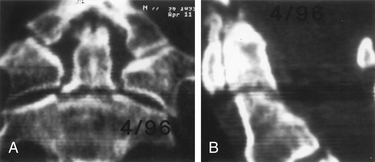
Degree and direction of offset may be misleading indicators because they have been identified based on single rather than dynamic radiographs (Fig. 142-2). However, age seems to be an important valid indicator of the propensity for nonunion. In a randomized controlled prospective study, Lennarson et al.18 found the nonunion rate was 21 times greater in patients older than 50 years who were treated with halo immobilization than in younger patients. This study was a key factor leading to a recommendation for surgery in the guidelines for management of acute cervical spine and spinal cord injuries published by the Joint Section of Disorders of the Spine and Peripheral Nerves of the American Association of Neurological Surgeons and Congress of Neurological Surgeons.19
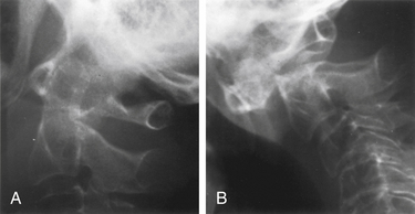
Because nonoperative treatment of type II odontoid fractures has a high nonunion rate (Fig. 142-3), several alternative methods of surgical fixation have been developed. The traditional operative technique for type II odontoid process fractures has been C1-2 dorsal wiring and arthrodesis. A relatively high fusion rate is associated with this technique; however, rigid postoperative bracing for at least 3 months is necessary, and successful fusion results in a significant reduction in head rotation. The dorsal approach also has an associated traumatic effect on cervical muscles. All these disadvantages can be obviated by using direct ventral odontoid screw fixation techniques.
Direct Ventral Odontoid Screw Fixation
Direct screw fixation of the odontoid process was first described in 1980 in the Japanese literature by Nakanishi,20 who began using this technique in 1978. This description was followed in 1981 and in 1982 by publications from Böhler,21,22 who reported his experience dating back to 1968. Although others23–26 described their experiences with various approaches to achieve direct odontoid screw fixation, the procedure was not widely accepted. With the development of specialized instrumentation facilitating accurate screw placement and minimal trauma to the patient,27–29 the procedure has gained in popularity. The technique has the advantages of (1) decreased postoperative pain resulting from lack of extensive muscle dissection, (2) avoidance of bone graft harvest, and (3) maintenance of normal anatomy and rotation at the C1-2 joint.30 Many patients require no postoperative immobilization.
Direct ventral odontoid screw fixation can be used as the primary approach to treat acute type II fractures. Patients with type II dens fractures with concomitant C1 ring fracture may also be candidates for odontoid screw fixation. However, assessment of transverse ligament integrity by MRI preoperatively31 and by flexion fluoroscopy postoperatively is essential. If the latter shows continued C1-2 instability, either a ventral or a dorsal C1-2 fusion is necessary. The direct screw fixation technique may also be used in some patients with chronic nonunion of type II odontoid fractures. Candidates should have a relatively small gap between the odontoid process and the C2 body and a reasonably sized odontoid fragment that has not autofused to C1 and does not have sclerosis of the surface opposing the body of C2. Chronic malunions that do not meet these criteria rarely fuse and ultimately fracture the hardware and become unstable. The chance of successful bony union in one small series of such patients with fractures of more than 18 months of age was only 25%32; this sharply contrasts with an 88% fusion rate for type II and high type III fractures of less than 6 months of age.32 For this reason, we generally recommend posterior C1-2 fusion for chronically nonunited fractures. Unstable type III odontoid fractures that do not extend too far into the body of C2 are also potential candidates for direct screw fixation.
Contraindications
Absolute contraindications include comminuted fractures of the C2 body and transverse ligament disruption, as defined by MRI or suggested by a C1 lateral mass fracture with extensive lateral displacement (>7 mm total on anteroposterior radiographs)33; pathologic fractures; and nonunions of fractures that occurred more than 6 to 8 months previously that do not meet the aforementioned criteria. A relative contraindication is severe osteoporosis. In addition, an oblique fracture of the odontoid process, angled caudally and ventrally so that it is parallel to the planned screw trajectory, may not be as suitable for ventral screw fixation because the odontoid process may slide down the fracture plane as the screw is tightened. Although they account for only 16% of the cases in one published series,32 these anterior oblique fractures had a significantly higher failure rate. By starting fixation in a position of slight retrolisthesis and augmenting the construct with a rigid cervical collar to restrict flexion, successful fusion has been achieved in patients with anterior oblique fractures.
Patient Positioning
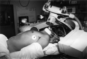
For odontoid or ventral C1-2 screw placement, biplanar fluoroscopy is necessary. The anteroposterior view is obtained transorally. A wine bottle cork, notched for the teeth or gums, is an ideal radiolucent mouth prop. A single fluoroscope, swung back and forth frequently from the lateral to the anteroposterior position, can be used if necessary. A triangular space for one side of the C-arm can be walled off with drapes and IV poles to facilitate frequent positioning and minimize the need to redrape the C-arm. It is much easier, however, to use a second C-arm fluoroscope if one is available. One C-arm unit is placed laterally with the arc horizontally or up to 45 degrees above the horizon. The other can be brought in at a 45-degree angle from the head of the table and positioned for the transoral view (Fig. 142-4).
Operative Technique
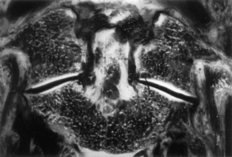
Several screw systems have been used, but all ventral odontoid fixations begin with the same exposure. The initial approach to the spine is the same as for an anterior cervical discectomy. The spine is approached at about the C5 level through a unilateral natural skin crease incision (Fig. 142-5). We use a local injection with epinephrine (1:200,000) to minimize skin bleeding and complete hemostasis with bipolar cautery. The platysma muscle is elevated and divided with monopolar cautery. The sternocleidomastoid muscle fascia is opened along the medial side of the muscle with sharp dissection. Blunt dissection opens the deeper tissue planes medial to the carotid sheath and lateral to the trachea and esophagus to expose the prevertebral space. Dividing the longus colli fascia and the anterior longitudinal ligament in the midline with electrocautery allows the bellies of the longus colli muscle to be elevated bilaterally over approximately 1.5 vertebral segments. Sharp-bladed Caspar retractor blades are set in place below the muscle and attached to the Caspar retractor.
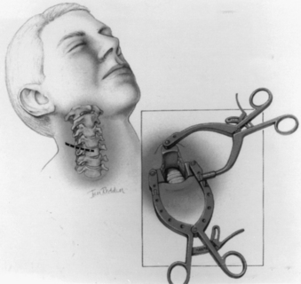
FIGURE 142-5 Skin incision in a natural skin crease at about the C5 level. Inset shows retractor in place.
The loose areolar tissue in the prevertebral space ventral to the longus colli muscles is easily opened with a Kittner or “peanut” dissector held in a curved tonsil clamp. It is swept from side to side while advancing up to the C1-2 level (monitored with lateral fluoroscopy). The Apfelbaum system (Aesculap Instrument Corporation, Center Valley, PA) has an angled retractor blade that reaches into this space under the mandible and holds open the working tunnel. It attaches to one side of the previously placed modified Caspar retractors (see Fig. 142-5). Other systems use different retractors, such as a curved hand-held retractor (Synthes) or small metal hook-shaped hand-held Hohmann retractors that lock over the shoulders of C2 bilaterally alongside the dens, as initially described by Böhler.21 The key to the retraction is to create a working tunnel up to the caudal edge of C2, without having any device caudally in the wound that restricts the low trajectory needed for proper screw placement.
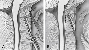
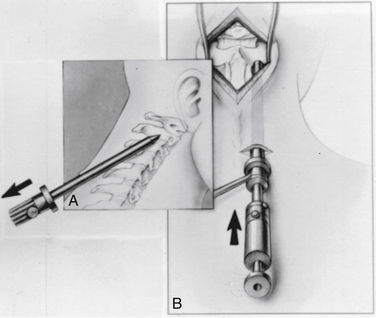
At this point, the various instrument systems use different approaches for placing the screws. The Apfelbaum system consists of an outer guide tube with spikes that anchor it to C3 and that can be used to optimize spinal alignment. An inner guide tube, within the outer tube, guides the drilling. After the pilot hole is drilled, the inner guide is removed, the hole is tapped, and the screws are placed through the outer guide tube. First, under biplanar fluoroscopic control, an entry site on the ventral caudal edge of C2 is selected, and a K-wire is impacted into C2 (Fig. 142-6A). If one screw is to be placed, a midline location is chosen. If two are to be placed, a paramedian location is selected 2 to 3 mm from the midline. Care and patience in selecting the entry site and setting the K-wire are rewarded by the remainder of the procedure being expedited. When the K-wire is set, a 7-mm hollow drill is placed over the K-wire and is rotated by hand to create a shallow trough in the face of C3 and in the C2-3 anulus (Fig. 142-6B–D).
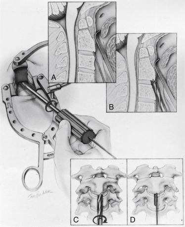
FIGURE 142-6 A, A guiding K-wire in place. B–D, Hollow hand drill creates a trough in the face of C3 and C2-3 anulus.
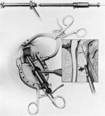
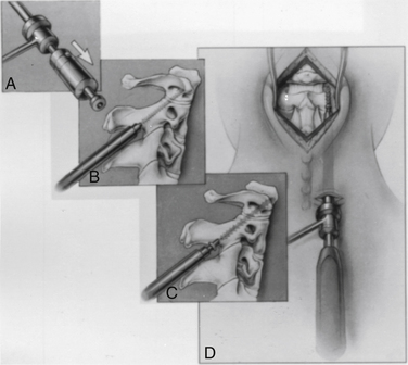
No bone is removed from C2. The two guide tubes are mated together, passed over the K-wire, and walked up the ventral face of the spinal column until the spikes on the outer tube are over the body of C3. The inner guide tube is advanced in the trough to the ventral caudal edge of C2 (Fig. 142-7), and the K-wire is removed. Having the guide tube at the entry site prevents the drill from skipping off the edge of the bone and walking up the ventral face of C2. With the guide tube system firmly engaged in C3, the surgeon can optimize the C2 alignment on the fluoroscopic images by either pushing C2 and C3 dorsally relative to the odontoid-C1 complex or pulling C2 and C3 ventrally. In the case of a retrolisthesed odontoid process, this realignment can be performed while gradually extending the patient’s head and removing the supporting towels beneath it to obtain an ideal working trajectory.
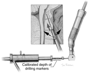
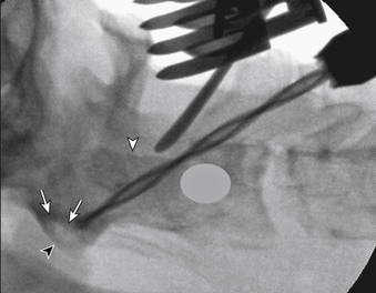
A pilot hole is drilled from the ventral caudal edge of C2 to the apex of the odontoid process, advancing the drill slowly under biplanar fluoroscopic control (Fig. 142-8). The dense cortical shell of the odontoid must be pierced to engage the screw properly and avoid splitting. Because the odontoid process is firmly held in position by its periosteum and attached supporting ligaments, it is not displaced as the drill enters from the soft cancellous fracture site. The angle of drilling is such that the drill can penetrate a substantial distance beyond the apex of the odontoid process into the apical ligaments without threatening the dural or neural structures. However, if a more dorsal trajectory is needed, greater care must be taken not to penetrate too far into the spinal canal; this is controlled by visualizing the progress of the drill on the fluoroscope.
The drill is withdrawn, and the inner guide tube is removed. A tap is placed through the outer guide tube, and the pilot hole is tapped. Threads are cut in the bone, allowing a more precise bone-screw junction that may reduce bone absorption around the screw caused by pressure necrosis if a self-tapping screw is used. The tap is removed, and a screw is placed through the guide tube (Fig. 142-9). A screw that is a few millimeters shorter than the measured drill depth may be chosen to allow for reduction at the fracture site, but it is important that the screw fully engages the apical cortex. Extending the screw a few millimeters beyond the cortex into the apical ligaments is safe and preferable to having one too short because the latter may (and has in our experience) back out. To achieve some fracture reduction, a partially threaded screw (lag screw) is used to pull the odontoid back toward the body of C2.
Several alternative systems have been proposed that are often based on existing long bone screw fixation techniques. These systems use a K-wire to drill the pilot hole and pass a hollow overdrill over this, followed by a cannulated screw.24 Theoretically, after the K-wire is placed, it does not have to be removed so that precise reentry into the same trajectory is assured; however, a drawback of these systems is that they do not appear to have any provision for optimizing alignment with the drill guide, as described earlier, except by trying to do this by repositioning the head or placing additional instruments beside the drill and pushing on C1 or C2. K-wires are suboptimal drills because they lack the torsional rigidity of drill bits and can be deflected by irregular densities within the bone. To redirect them, one must remove the K-wire and select a new starting point.34 In addition, great care must be taken when drilling over the K-wire because the drill can bind to the K-wire and advance it into the spinal canal or cut the K-wire. This can also occur when placing the screw over the K-wire.
Controversies
One-Screw Constructs versus Two-Screw Constructs
Theoretically, with one screw, the odontoid process could rotate on C2, although with fresh fractures the interdigitation of the irregular fracture surfaces may prevent this; this may explain why both techniques have been reported to have similar clinical success.35–37 Laboratory studies also show no greater resistance to screw fracture from bending with one-screw or two-screw constructs. However, a more recent clinical study by Dailey et al.38 found a significant difference in fusion rates among 57 patients older than 70 years with odontoid fractures: a 56% success rate was achieved if one screw was placed, whereas a 95% fusion rate was achieved when two screws were placed. The different outcomes between this study and the previously mentioned ones are likely due to the fact that the earlier studies had a much younger patient population.
When two screws are placed, the entry site for each is located paramedially a few millimeters off the midline and the screws are angled toward each other at the odontoid apex. The diameter of the odontoid process should be assessed on the preoperative CT scan to ensure adequate bone volume for a second screw. Some patients may not have a sufficiently wide odontoid process to accommodate two screws side by side,39 but the process may be deep enough that the screws can be placed in such a way that they end up in front of and behind each other to achieve the same fixation.
Screw Size and Type
Biomechanical data suggest that cannulated screws are only about 5% to 10% weaker than solid screws.34 Various screw diameters have been used. These usually range from 3.5 to 4.0 mm and are occasionally larger. The initial experience was with cancellous threaded screws, which have a deeper thread (smaller minor diameter or core) and are better at resisting pull-out. However, pull-out forces on odontoid screws are minimal. An odontoid screw primarily has to resist bending and translational forces. Screw failure, if it occurs, is almost always due to fracture at the level of the bone fracture. Cortically threaded screws (4-mm outer diameter) with a larger minor diameter (2.9 mm vs. the previously used 2 mm) would seem optimal. Such screws have proven substantially stronger in laboratory tests, in which they fail to fracture after 1 million cycles at three times the load at which the older screws fractured at 33,100 cycles. In the experience of the senior author (R.I.A.), these screws are also more effective; no postoperative screw fractures were observed in more than 400 consecutive screw placements compared with a 5% fracture rate in odontoid fixation and 10% fracture rate in C1-2 fixation with the prior screw design. An additional benefit is that the pilot hole is drilled larger (3 mm vs. 2 mm); this makes the drill much more directionally stable, allowing precise correction of pilot hole trajectory to optimize screw placement.
Results
Type II odontoid fractures less than 6 months old treated with this technique have a high rate of fusion. The combined published series32 of Veres in Hungary and Apfelbaum et al. in Salt Lake City, Utah, encompassed 147 patients whose ages ranged from 15 to 92 years. Successful bony union was achieved in 88% of patients, with an additional 3% achieving stability via fibrous union. These results agree with the results of other published series with fewer patients.25,26,34,40,41 Failures usually occur in elderly patients with poor quality bone. In such circumstances, the screw may fail to hold in C2, in particular, if there is an associated fracture in the body of C2. If this complication is recognized early, manipulative realignment and external immobilization have been successful. If not, additional surgery was required. There was one late neurologic complication in which a patient became quadriplegic in the series from Hungary when the construct failed to hold and the fracture subsequently dislocated. There were no other neurologic complications, and other surgical complications are rare.
Other series have shown similar low complication rates; however, there has been a high incidence of dysphagia from the retropharyngeal approach in elderly patients, and some of these patients required temporary feeding tubes.38 Although there are no published results detailing complications when using one of the cannulated systems, numerous serious and even fatal complications are known to result from the K-wire being driven in beyond the odontoid tip.
Ventral C1-2 Transarticular Screw Fixation
Ventral C1-2 transarticular screw fixation may provide an alternative if odontoid screw fixation is impossible or if successful odontoid screw fixation fails to stabilize C2 because of unrecognized concomitant transverse ligament incompetence. Stabilization is accomplished by inserting two screws through the lateral masses of C2 into the lateral mass of C1.42 The entry site is just medial to the vertebral artery, which is placed at risk by this approach. The screws angle laterally about 20 degrees and dorsally at a similar angle. The entry site is selected by following the lateral edge of the vertebral body rostrally from the C2-3 interspace to its junction with the lateral mass, staying as medial as possible in that structure. The drill guide system used for odontoid screw fixation can be used for this as well, although the screw length is considerably shorter.
Other Ventral Techniques
There are a few reports of using plates and screws transorally.43 Experience with these is limited because they do not appear to have been widely used. The risk of infection and, to a lesser extent, the limited working space seem to have deterred most surgeons from these approaches.
Dorsal Approaches
Traditional techniques have used various C1-2 wiring strategies with interposed or onlay bone grafting (Gallie,44 Brooks,45 and interspinous [Sonntag]46 fusions). Because these impart limited stability that deteriorates significantly with cyclic loading,47 an external rigid orthosis is usually necessary. Fractured or absent dorsal elements can preclude the use of these techniques. Even in optimal situations, nonunion rates of 30% are reported.47
Transarticular screw fixation, pioneered by Magerl in 1979, offers immediate stabilization, often without external orthosis.48 By optimizing bone graft union with a high chance of success, transarticular screw fixation is a major advance in treating instability in this area. The construct can be extended with various devices to include the occiput and the subaxial spine if needed.
Contraindications
Poor bone quality is always of concern during intraosseous fixation and must be evaluated carefully. It is not an absolute contraindication to surgery but may necessitate using both internal and external devices. Of paramount importance for transarticular screw fixation is an adequate pathway for the screw that traverses the pars interarticularis (isthmus) of C2 (not the pedicle) to the lateral C1-2 articulation before crossing that joint into the lateral mass of C1. Variations in anatomy and secondary effects of vascular elongation coupled with bone softening can result in the vertebral artery looping up into the pars of C2. This looping of the vertebral artery may occur to such an extent that an inadequate pathway remains for safe screw placement. Placing screws in such circumstances has resulted in vertebral artery injury with potentially serious neurologic sequelae. An alternative technique devised by Harms and Melcher49 uses screws placed in the lateral masses of C1 and into the C2 pars or pedicle, which are connected posteriorly with rods. This technique is applicable in cases in which a safe pathway through the C2 pars to C1 does not exist. Another approach using translaminar screws in C2 that are then coupled to C1 screws has been proposed by Wright.50
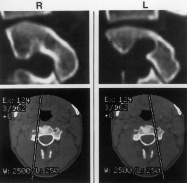
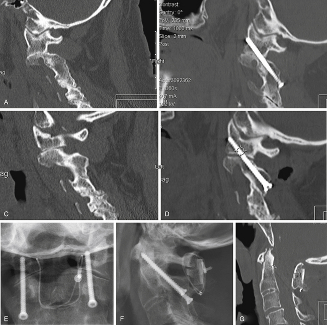
Understanding the patient’s anatomy and the availability of a safe bony pathway for screw placement before proceeding with the surgery is crucial. We obtain thin-section CT scans and build images that are not just in orthogonal planes but are also reconstructed along the planned screw pathways. This construction of images can be done on the consoles of most CT scanners. Alternatively, importing the images into a stereotaxic workstation allows the surgeon to look at various possible pathways and build a three-dimensional model that can be viewed in the operating room. This approach has been invaluable in evaluating whether screws can be passed safely (Fig. 142-10) and in assisting in achieving the desired pathway during surgery.
Patient Positioning
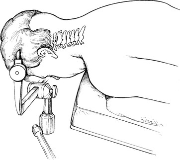
A Mayfield three-pin head holder and a cervical collar are placed. The patient is rolled into prone position on bolsters while the surgeon keeps the neck stable with axial traction and maintains it in a neutral position. Before the head clamp is secured to the table, final positioning is performed under lateral fluoroscopic guidance. The best reduction position is often with the neck in extension, but this may preclude C1-2 transarticular screw placement in many cases because lordosis would often dictate a screw trajectory starting within the thoracic cavity. The patient should be positioned with the chin slightly flexed but with the head pulled dorsally (Fig. 142-11). This position has been likened to the posture of military personnel standing at braced attention. This position usually reduces C1-2 dislocations via dorsal translation but leaves the rest of the cervical spine in a flattened or even slightly kyphotic posture so that the needed screw trajectory can be achieved. The head should also be positioned so that it is not rotated; this can be judged by the symmetry of the ear canals relative to the table or floor. Careful monitoring of the fluoroscopic image facilitates safe positioning. An absolutely perfect position is unnecessary; minor residual translational movements are accepted because these can easily be corrected at the time of screw placement.
Operative Technique
A dorsal midline incision extending from just below the inion to C3 is usually adequate (Fig. 142-12A). The paraspinal muscles are dissected off the dorsal elements of C1, C2, and the occipital bone and are held back with angled Weitlaner retractors. The exposure may require sharp dissection assisted with electrocautery if the spine is unstable. The full extent of the dorsal elements of C1 and C2 should be exposed, with definition of the lateral aspect of the C2 dorsal elements and the C2-3 facet joint and of the C2 isthmus extending rostrally beneath the C2 nerve root and the associated venous complex (Fig. 142-12B). Bleeding can usually be arrested with small hemostatic gelatin (Gelfoam) pledgets soaked in thrombin or a slurry made with Gelfoam powder and thrombin. It is neither necessary nor desirable to disconnect the inferior midline attachments to the bifid C2 spinous process.
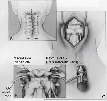
A 1- to 1.5-cm skin transverse incision carried down through the dorsal fascia provides an entry for the drill apparatus (see Fig. 142-12A). As with odontoid fixation, a guide tube system (Aesculap Instrument Corporation) may be used. With this system, a smooth tube fitted with a conical tipped obturator is passed from the skin incision up to the drill entry site at the C2-3 junction by pressing firmly in a rostral direction and gently rotating the instrument back and forth to advance it into the surgical field (Fig. 142-12C). When the guide tube is in place, the obturator is removed, and an awl is used to make a starting hole in the C2 laminar bone. An inner drill guide is placed to support the drill (Fig. 142-13). The guide tube assembly allows precise control of the drilling direction.
The surgeon must visualize the dorsal lateral and medial borders of the pars interarticularis and direct the drill bit accurately between these limits. A tool, such as a small Penfield dissector held by an assistant, can help visualization of this area. Because it is placed on the dorsum of the pars, it serves as a fluoroscopic marker for that boundary. A low-angled trajectory to carry the drill bit just below the dorsum of the pars and across the C1-2 lateral articulation, as far dorsally as possible, engages the maximum amount of the lateral mass of C1 and keeps the drill above the vertebral artery. On the lateral fluoroscopic image (Fig. 142-14), the projection of the ventral arch of C1 is a helpful target to aim for, especially at its rostral margin. Generally, the screw trajectory should be in a straight paramedian direction or slightly medially as dictated by the bone anatomy and location of the vertebral artery foramen. Aiming too far medially results in a smaller area of C1 lateral mass engagement, whereas aiming laterally can jeopardize the vertebral artery.
When drilling, increased resistance is felt at the cortical margins of the C2 joint surface, and then at the C1 joint surface and at the ventral cortex of C1. If necessary, C2 can be translated ventrally or dorsally before drilling across the joint space by grasping the spinous process of C2 with a towel clamp, ensuring optimal alignment. When the pilot hole is drilled, the depth is noted on the calibrated drill shaft, and the images are stored. The drill and inner drill guide are replaced with a tap (Fig. 142-15) except in very soft bone. After the hole is tapped, a fully threaded screw is placed because no lag effect is needed. Vertebral alignment is reoptimized just before the C1-2 articulation is crossed by matching the active fluoroscopic image with its stored counterpart. If a polyaxial screw is being used, as in the Harms construct, for example, or to extend the construct to the occiput, a guide tube with an additional inner sleeve is used. Removal of the sleeve increases the inner diameter of the tube so that the polyaxial screw can be placed.
Bone bleeding may occur, in particular, in patients with inflammatory disease. However, if brisk arterial bleeding ensues from the drill hole, suggesting a vertebral artery injury, placement of one screw for fixation and tamponade is recommended, but a second screw should not be placed. If this occurs, it would be prudent to obtain postoperative angiographic images to ascertain the status of the vessel and to detect fistula formation.51
Bone Grafting
Screw fixation functions as an internal splint. For long-term stability, bone fusion is required because all hardware ultimately fails without it. Magerl and Seeman48 suggested curetting and then packing bone chips into the C1-2 articulation to encourage arthrodesis. Access to this joint is limited, however, and only a small portion of it can be treated in this manner even in ideal circumstances. We use a dorsal fusion construct if possible.
With intact dorsal elements, a modified construct consisting of a combined interpositional and onlay bicortical iliac crest graft was suggested by Sonntag’s group.46 The graft has ventral and dorsal cortices. After the mating surfaces have been denuded with a high-speed bur, the contact sites at the caudal surface of C1 and the laminar surface and rostral edge of the spinous process of C2 are to cancellous bone. The graft and donor surfaces are also contoured for maximum apposition (Fig. 142-16). The graft is secured with a braided titanium cable placed sublaminarly at C1 and around the spinous process of C2, so that the graft is sandwiched between the two layers of cable. This construct provides excellent three-dimensional stability. The screws resist translation and rotation, whereas the graft prevents extension, and the cable prevents flexion. Additional bone chips and curettings may be placed around the construct to enhance fusion.
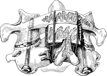
FIGURE 142-16 Illustration of completed screw fixation. This was the technique originally suggested by Sonntag’s group and shows the cabling technique we prefer to use. In contrast to this illustration, however, we notch the graft to contact both the dorsal and the caudal edge of the C1 laminar arch (see Fig. 142-17) and extend it over and into the lamina of C2 to improve the fusion potential at this site.
(From Marcotte P, Dickman CA, Sonntag VKH, et al: Posterior atlantoaxial facet screw fixation. J Neurosurg 79:234–237, 1993.)
There are significant advantages to being able to use allograft bone as the graft, including elimination of donor site pain and complications, reduced bleeding, and ability to select more optimal bone. Although allograft usually has been unsuccessful in onlay constructs, by modifying the C1-2 dorsal graft placement further so that the graft is notched to fit in close apposition to both the dorsal and the inferior edges of C1 and is mortised into the lamina of C2, we achieve a true interpositional graft (Fig. 142-17). Coupling this graft with internal screw fixation to eliminate all motion has allowed us to use bicortical iliac crest allograft bone with fusion results equal to autograft in this application and significantly reduced patient morbidity (Fig. 142-18).52
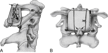
FIGURE 142-17 Lateral (A) and posterior (B) views showing the modified grafting technique to increase the graft contact along the inferior aspect of the C1 ring and its dorsal aspect (small black arrows in A). Both of these surfaces of C1 are decorticated and flattened to maximize graft contact. The bicortical graft is also mortised into the decorticated lamina of C2 (large black arrow in A) and contacts the decorticated spinous process of C2 (arrows in B). The artist has shown wiring, but braided titanium cable is used and placed as described by Dickman et al.,46 enveloping the graft anteriorly and posteriorly with a cable that passes under the C1 posterior ring and behind the spinous process of C2. Leaving the interspinous ligaments intact on the spinous process of C2 (not shown) helps retain the cable. This graft modification improves grafting success with autograft and allows an equally good result with bicortical iliac crest allograft if desired.52
Alternative Systems
Drilling with a K-wire and placing hollow cannulated screws is an alternative technique used by some surgeons.34 The K-wire may be drilled percutaneously or via a similarly placed guide tube. The concerns expressed earlier with regard to lack of precise directional control and the risks of inadvertently advancing the K-wire with the drill and cutting the K-wire pertain here as well.
Results and Complications
Numerous series report excellent stabilization and fusion rates. Magerl and Seeman’s initial series48 reported a 100% fusion rate; Grob et al.53 reported a 99% success rate in 161 patients; Stillerman and Wilson54 reported a 95% rate of successful fusion (21 out of 22 patients); and Marcotte et al.55 had a 100% rate of fusion in 18 patients. Gluf et al.56 reported successful fusion in 98% of 191 adult patients and had similar results in an additional 78 patients since that publication.
The procedure is technically demanding. It requires a good knowledge of nuances in anatomy and thorough preoperative evaluation via high-resolution CT scans, preferably with reconstruction along the screw pathway. Neurologic complications from direct injury have not been reported; however, vertebral artery injuries have occurred, and in one case bilateral vertebral artery injuries resulted in a fatal brainstem infarction.57 Unilateral injuries have not resulted in neurologic sequelae but have produced arteriovenous fistulae, one of which manifested as a delayed spinal cord compromise from epidural venous engorgement.51
Occipitocervical Fusion
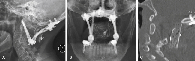
Instability or degeneration of the occiput-C1 joint or basilar invagination may require incorporation of the occiput into an upper cervical fusion. In the past, various plates or rod and plate devices were used to extend the hardware up from the C1-2 screws. The disadvantages with these systems have been resolved by using polyaxial screws at C1-2 (or individually at C1 and C2 if the Harms or Wright techniques are used). A contoured rod from these can be attached to a plate that is secured to the occiput (Fig. 142-19). Besides being easier to apply, the occipital plate can be fixed to the midline bone, which is the thickest and strongest portion of the occiput. A longer graft secured in the same manner as described for C1-2 fusions can be extended to the occiput and apposed to a denuded area to maximize incorporation potential. A small bone screw inserted through the graft into the occiput can enhance this contact.
Summary
Screw fixation techniques have proven to be safe and extremely effective in the upper cervical spine. This highly mobile area has been difficult to stabilize reliably and effectively using other techniques. Previously used operative and nonoperative techniques have been only partially effective in addressing the problem of instability in this area. In addition, the techniques have often required prolonged rigid external immobilization resulting in prolonged inability to function normally or sacrifice of more normal motion than necessary to gain protection for the neural elements. The two major screw fixation techniques in this region—direct screw fixation of odontoid fractures and C1-2 screw fixation techniques—are extremely important additions to the surgeon’s armamentarium. The available data suggest that these techniques are superior to other approaches.
Acknowledgment
The authors thank Kristin Kraus, MSc, for editorial assistance in preparing this chapter.
Apfelbaum R.I., Lonser R.R., Veres R., et al. Direct anterior screw fixation for recent and remote odontoid fractures. J Neurosurg. 2000;93(suppl 2):227-236.
Dailey A., Hart D., Finn M., et al. Anterior fixation of odontoid fractures in an aging population. J Neurosurg Spine. 2010;12:1-8.
Dickman C.A., Sonntag V.K., Papadopoulos S.M., et al. The interspinous method of posterior atlantoaxial arthrodesis. J Neurosurg. 1991;74:190-198.
Gluf W.M., Schmidt M.H., Apfelbaum R.I. Atlantoaxial transarticular screw fixation: a review of surgical indications, fusion rate, complications, and lessons learned in 191 adult patients. J Neurosurg Spine. 2005;2:155-163.
Grob D., Jeanneret B., Aebi M., et al. Atlanto-axial fusion with transarticular screw fixation. J Bone Joint Surg [Br]. 1991;73:972-976.
Harms J., Melcher R.P. Posterior C1-C2 fusion with polyaxial screw and rod fixation. Spine (Phila Pa 1976). 2001;26:2467-2471.
Hillard V.H., Fassett D.R., Finn M.A., et al. Use of allograft bone for posterior C1-2 fusion. J Neurosurg Spine. 2009;11:396-401.
Lennarson P.J., Mostafavi H., Traynelis V.C., et al. Management of type II dens fractures: a case-control study. Spine (Phila Pa 1976). 2000;25:1234-1237.
Magerl F., Seeman P.S. Stable posterior fusion of the atlas and axis by transarticular screw fixation. In: Kehr P., Weidner A., editors. Cervical spine i. New York: Springer-Verlag; 1987:322-327.
Stillerman C.B., Wilson J.A. Atlanto-axial stabilization with posterior transarticular screw fixation: technical description and report of 22 cases. Neurosurgery. 1993;32:948-954.
1. White A.A.3rd, Panjabi M.M. The occipital-atlanto-axial complex (C0-C1-C2). White A.A.3rd, Panjabi M.M., editors. Clinical biomechanics of the spine, ed 2. Philadelphia: Lippincott-Raven. 1990:92-97.
2. Tuite G.F., Papadopoulos S.M., Sonntag V.K. Caspar plate fixation for the treatment of complex hangman’s fractures. Neurosurgery. 1992;30:761-764.
3. Anderson L.D., D’Alonzo R.T. Fractures of the odontoid process of the axis. J Bone Joint Surg [Am]. 1974;56:1663-1674.
4. Scott E.W., Haid R.W.Jr., Peace D. Type I fractures of the odontoid process: implications for atlanto-occipital instability: case report. J Neurosurg. 1990;72:488-492.
5. Benzel E.C., Hart B.L., Ball P.A., et al. Fractures of the C-2 vertebral body. J Neurosurg. 1994;81:206-212.
6. Lind B., Nordwall A., Sihlbom H. Odontoid fractures treated with halo-vest. Spine (Phila Pa 1976). 1987;12:173-177.
7. Maiman D.J., Larson S.J. Management of odontoid fractures. Neurosurgery. 1982;11:471-476.
8. Althoff B. Fracture of the odontoid process: an experimental and clinical study. Acta Orthop Scand Suppl. 1979;177:1-95.
9. Blockey N.J., Purser D.W. Fractures of the odontoid process of the axis. J Bone Joint Surg [Br]. 1956;38:794-817.
10. Hentzer L., Schalimtzek M. Fractures and subluxations of the atlas and axis: a follow-up study of 20 patients. Acta Orthop Scand. 1971;42:251-258.
11. Pepin J.W., Bourne R.B., Hawkins R.J. Odontoid fractures, with special reference to the elderly patient. Clin Orthop Relat Res. 1985;193:178-183.
12. Schatzker J., Rorabeck C.H., Waddell J.P. Fractures of the dens (odontoid process): an analysis of thirty-seven cases. J Bone Joint Surg [Br]. 1971;53:392-405.
13. Julien T.D., Frankel B., Traynelis V.C., et al. Evidence-based analysis of odontoid fracture management. Neurosurg Focus. 2000;8(6):E1.
14. Hadley M.N., Browner C., Sonntag V.K. Axis fractures: a comprehensive review of management and treatment in 107 cases. Neurosurgery. 1985;17:281-290.
15. Apuzzo M.L., Heiden J.S., Weiss M.H., et al. Acute fractures of the odontoid process: an analysis of 45 cases. J Neurosurg. 1978;48:85-91.
16. Dunn M.E., Seljeskog E.L. Experience in the management of odontoid process injuries: an analysis of 128 cases. Neurosurgery. 1986;18:306-310.
17. Hadley M.N., Browner C.M., Liu S.S., et al. New subtype of acute odontoid fractures (type IIA). Neurosurgery. 1988;22(1 pt 1):67-71.
18. Lennarson P.J., Mostafavi H., Traynelis V.C., et al. Management of type II dens fractures: a case-control study. Spine (Phila Pa 1976). 2000;25:1234-1237.
19. Isolated fractures of the axis in adults. Neurosurgery. 2002;50(Suppl 3):S125-S139.
20. Nakanishi T. Internal fixation of the odontoid fracture [Japanese]. Cent Jpn J Orthop Traumatic Surg. 1980;23:399-406.
21. Böhler J. Anterior stabilization for acute fractures and non-unions of the dens. J Bone Joint Surg [Am]. 1982;64:18-27.
22. Böhler J. Schraubenosteosynthese von Frakturen de dens axis. Unfallchirurgie. 1981;84:221-223.
23. Borne G.M., Bedou G.L., Pinaudeau M., et al. Odontoid process fracture osteosynthesis with a direct screw fixation technique in nine consecutive cases. J Neurosurg. 1988;68:223-226.
24. Esses S.I., Bednar D.A. Screw fixation of odontoid fractures and nonunions. Spine (Phila Pa 1976). 1991;16(Suppl 10):S483-S485.
25. Geisler F.H., Cheng C., Poka A., et al. Anterior screw fixation of posteriorly displaced type II odontoid fractures. Neurosurgery. 1989;25:30-37.
26. Lesoin F., Autricque A., Franz K., et al. Transcervical approach and screw fixation for upper cervical spine pathology. Surg Neurol. 1987;27:459-465.
27. Apfelbaum R. Anterior screw fixation for odontoid fractures. In: Camins M., O’Leary P., editors. Disorders of the cervical spine. Baltimore: Williams & Wilkins; 1992:603-608.
28. Apfelbaum R. Anterior screw fixation of odontoid fractures. Rengachary S., Wilkins R., editors. Neurosurgical operative atlas. Baltimore: Williams & Wilkins. 1992;vol 2:189-199.
29. Apfelbaum R. Screw fixation of odontoid fractures. In: Wilkins R., Rengachary S., editors. Neurosurgery. New York: McGraw-Hill; 1996:2965-2973.
30. Jeanneret B., Vernet O., Frei S., et al. Atlantoaxial mobility after screw fixation of the odontoid: a computed tomographic study. J Spinal Disord. 1991;4:203-211.
31. Dickman C.A., Mamourian A., Sonntag V.K., et al. Magnetic resonance imaging of the transverse atlantal ligament for the evaluation of atlantoaxial instability. J Neurosurg. 1991;75:221-227.
32. Apfelbaum R.I., Lonser R.R., Veres R., et al. Direct anterior screw fixation for recent and remote odontoid fractures. J Neurosurg. 2000;93(suppl 2):227-236.
33. Spence K.F.Jr., Decker S., Sell K.W. Bursting atlantal fracture associated with rupture of the transverse ligament. J Bone Joint Surg [Am]. 1970;52:543-549.
34. Dickman C.A., Foley K.T., Sonntag V.K., et al. Cannulated screws for odontoid screw fixation and atlantoaxial transarticular screw fixation. Technical note. J Neurosurg. 1995;83:1095-1100.
35. Jenkins J.D., Coric D., Branch C.L.Jr. A clinical comparison of one- and two-screw odontoid fixation. J Neurosurg. 1998;89:366-370.
36. Sasso R., Doherty B.J., Crawford M.J., et al. Biomechanics of odontoid fracture fixation: comparison of the one- and two-screw technique. Spine (Phila Pa 1976). 1993;18:1950-1953.
37. Subach B.R., Morone M.A., Haid R.W.Jr., et al. Management of acute odontoid fractures with single-screw anterior fixation. Neurosurgery. 1999;45:812-819.
38. Dailey A., Hart D., Finn M., et al. Anterior fixation of odontoid fractures in an aging population. J Neurosurg Spine. 2010;12:1-8.
39. Schaffler M.B., Alson M.D., Heller J.G., et al. Morphology of the dens: a quantitative study. Spine (Phila Pa 1976). 1992;17:738-743.
40. Etter C., Coscia M., Jaberg H., et al. Direct anterior fixation of dens fractures with a cannulated screw system. Spine (Phila Pa 1976). 1991;16(suppl 3):S25-S32.
41. Montesano P.X., Anderson P.A., Schlehr F., et al. Odontoid fractures treated by anterior odontoid screw fixation. Spine (Phila Pa 1976). 1991;16(suppl 3):S33-S37.
42. Dickman C.A., Sonntag F.K.H., Marcotte P.J. Techniques of screw fixation of the cervical spine. BNI Quarterly. 1992;8:9-26.
43. Goel A., Karapurkar A.P. Transoral plate and screw fixation of the craniovertebral region—a preliminary report. Br J Neurosurg. 1994;8:743-745.
44. Gallie W. Fractures and dislocations of the upper cervical spine. Am J Surg. 1939;46:495-499.
45. Brooks A.L., Jenkins E.B. Atlanto-axial arthrodesis by the wedge compression method. J Bone Joint Surg [Am]. 1978;60:279-284.
46. Dickman C.A., Sonntag V.K., Papadopoulos S.M., et al. The interspinous method of posterior atlantoaxial arthrodesis. J Neurosurg. 1991;74:190-198.
47. Dickman C.A., Crawford N.R., Paramore C.G. Biomechanical characteristics of C1-2 cable fixations. J Neurosurg. 1996;85:316-322.
48. Magerl F., Seeman P.S. Stable posterior fusion of the atlas and axis by transarticular screw fixation. In: Kehr P., Weidner A., editors. Cervical spine I. New York: Springer-Verlag; 1987:322-327.
49. Harms J., Melcher R.P. Posterior C1-C2 fusion with polyaxial screw and rod fixation. Spine (Phila Pa 1976). 2001;26:2467-2471.
50. Wright N.M. Posterior C2 fixation using bilateral, crossing C2 laminar screws: case series and technical note. J Spinal Disord Tech. 2004;17:158-162.
51. Coric D., Branch C.L.Jr., Wilson J.A., et al. Arteriovenous fistula as a complication of C1-2 transarticular screw fixation: case report and review of the literature. J Neurosurg. 1996;85:340-343.
52. Hillard V.H., Fassett D.R., Finn M.A., et al. Use of allograft bone for posterior C1-2 fusion. J Neurosurg Spine. 2009;11:396-401.
53. Grob D., Jeanneret B., Aebi M., et al. Atlanto-axial fusion with transarticular screw fixation. J Bone Joint Surg [Br]. 1991;73:972-976.
54. Stillerman C.B., Wilson J.A. Atlanto-axial stabilization with posterior transarticular screw fixation: technical description and report of 22 cases. Neurosurgery. 1993;32:948-954.
55. Marcotte P., Dickman C.A., Sonntag V.K., et al. Posterior atlantoaxial facet screw fixation. J Neurosurg. 1993;79:234-237.
56. Gluf W.M., Schmidt M.H., Apfelbaum R.I. Atlantoaxial transarticular screw fixation: a review of surgical indications, fusion rate, complications, and lessons learned in 191 adult patients. J Neurosurg Spine. 2005;2:155-163.
57. Apfelbaum R. Screw fixation of the upper cervical spine: indications and techniques. Contemp Neurosurg. 1994;16:1-81.
[/level-membership-for-neurosurgery-category][not-level-membership-for-neurosurgery-category]
Chapter 142 Upper Cervical Screw Fixation Techniques
Internal fixation is often used to provide immediate stabilization to protect the vital neural and vascular elements rendered vulnerable by instability produced by trauma, disease processes such as rheumatoid arthritis or neoplasms, and surgical procedures such as transoral odontoidectomy. Immediate stabilization is especially important in the highly mobile cervical spine. The occipitocervical junction and atlantoaxial complex constitute a transitional region connecting the rest of the spinal column to the cranium. The vertebrae and joints in this area differ from the vertebrae and joints in the subaxial spine, with special modifications to allow unique degrees of motion. Possibly the most important of these are at the C1-2 complex, where the flat lateral articulations, absence of an intervertebral disc, and lax ligaments permit appreciable rotation at C1-2 (about 50% of total head rotation) (Fig. 142-1).1 This motion is safely tolerated because the spinal canal is more generous, the instantaneous axis of rotation is located close to the spinal cord (minimizing distortion of that structure), and the vertebral arteries loop laterally (allowing for at least one to remain patent, even at the extremes of rotation). Potentially catastrophic translational movements, which would crush the spinal cord, are prevented by the very strong transverse component of the cruciate ligament (usually 8 to 10 mm in diameter in adults) that contains the odontoid process of the axis in the ventral compartment of the atlas. Disruption of this ligament, with or without bursting of the ring of C1 (Jefferson fracture), or disruption of the odontoid process results in gross instability. The remaining ligamentous structures, if intact, may provide some support, but they are too weak intrinsically to protect the spinal cord from even relatively minor trauma.
General Considerations
Protection of the neural elements when instability exists is paramount. Before surgery, the patient must be properly immobilized. Depending on the degree of instability, immobilization may be achieved with a rigid cervical collar, or it may require skeletal traction, a halo vest, or a Minerva jacket. Ongoing spinal canal compromise, if present, should be corrected before fusion is attempted by restoring alignment with cervical traction via cranial tongs or by surgical removal of intraspinal masses. After the nature of the pathologic condition has been fully investigated and restoration of physiologic relationships between neural elements and the spinal column has been managed, surgical stabilization can be planned. The overall medical condition of the patient should be optimized, and other injuries should be evaluated and treated as appropriate.
Ventral Approaches
Indications
Ventral techniques are primarily indicated for direct screw fixation of odontoid process fractures. C2-3 ventral fusion and plating may be used for hangman’s fracture.2 It is no different from ventral cervical fusion and plating at lower levels other than the difficulty associated with the angle of approach to C2. The retractor system used for odontoid screw fixation sometimes may be useful in this regard.
Odontoid process fractures were classified by Anderson and D’Alonzo3 as types I, II, and III. Type I fractures involve the apical part of the odontoid process, are quite rare, and are usually believed to be stable. However, one report suggested otherwise,4 and dynamic imaging should be used to assess stability. Type II fractures involve the neck of the odontoid process and are the most common. Type III fractures extend into the body of C2 and generally heal well with immobilization. However, in a comprehensive review of fractures of the C2 vertebral body, Benzel et al.5 noted that the type III fracture described by Anderson and D’Alonzo3 is not an odontoid fracture at all. Benzel et al.5 proposed a classification of C2 body fractures that is more comprehensive and more meaningful in regard to mechanisms of injury.
Debate continues regarding the optimal treatment of type II fractures. Reported nonunion rates range from 7%6 to 100%.7–12 A meta-analysis13 found that halo vest immobilization produced a fusion rate of 65%. The variable success of immobilization led some authors to try to define parameters that would predict failure with external immobilization. Extent of dislocation (67% nonunion if dislocation is >6 mm,14 88% nonunion with dislocation >4 mm15), patient age (higher failure rate in older patients15,16), and direction of subluxation (higher failure rate with dorsal subluxation16) all have been suggested as predictors, as has a comminuted fragment of bone at the base of the odontoid process (type IIA).17 Although these studies fail to agree on many points, they do emphasize the nature of the problem.
Degree and direction of offset may be misleading indicators because they have been identified based on single rather than dynamic radiographs (Fig. 142-2). However, age seems to be an important valid indicator of the propensity for nonunion. In a randomized controlled prospective study, Lennarson et al.18 found the nonunion rate was 21 times greater in patients older than 50 years who were treated with halo immobilization than in younger patients. This study was a key factor leading to a recommendation for surgery in the guidelines for management of acute cervical spine and spinal cord injuries published by the Joint Section of Disorders of the Spine and Peripheral Nerves of the American Association of Neurological Surgeons and Congress of Neurological Surgeons.19
Because nonoperative treatment of type II odontoid fractures has a high nonunion rate (Fig. 142-3), several alternative methods of surgical fixation have been developed. The traditional operative technique for type II odontoid process fractures has been C1-2 dorsal wiring and arthrodesis. A relatively high fusion rate is associated with this technique; however, rigid postoperative bracing for at least 3 months is necessary, and successful fusion results in a significant reduction in head rotation. The dorsal approach also has an associated traumatic effect on cervical muscles. All these disadvantages can be obviated by using direct ventral odontoid screw fixation techniques.
Direct Ventral Odontoid Screw Fixation
Direct screw fixation of the odontoid process was first described in 1980 in the Japanese literature by Nakanishi,20 who began using this technique in 1978. This description was followed in 1981 and in 1982 by publications from Böhler,21,22 who reported his experience dating back to 1968. Although others23–26 described their experiences with various approaches to achieve direct odontoid screw fixation, the procedure was not widely accepted. With the development of specialized instrumentation facilitating accurate screw placement and minimal trauma to the patient,27–29 the procedure has gained in popularity. The technique has the advantages of (1) decreased postoperative pain resulting from lack of extensive muscle dissection, (2) avoidance of bone graft harvest, and (3) maintenance of normal anatomy and rotation at the C1-2 joint.30 Many patients require no postoperative immobilization.
Direct ventral odontoid screw fixation can be used as the primary approach to treat acute type II fractures. Patients with type II dens fractures with concomitant C1 ring fracture may also be candidates for odontoid screw fixation. However, assessment of transverse ligament integrity by MRI preoperatively31 and by flexion fluoroscopy postoperatively is essential. If the latter shows continued C1-2 instability, either a ventral or a dorsal C1-2 fusion is necessary. The direct screw fixation technique may also be used in some patients with chronic nonunion of type II odontoid fractures. Candidates should have a relatively small gap between the odontoid process and the C2 body and a reasonably sized odontoid fragment that has not autofused to C1 and does not have sclerosis of the surface opposing the body of C2. Chronic malunions that do not meet these criteria rarely fuse and ultimately fracture the hardware and become unstable. The chance of successful bony union in one small series of such patients with fractures of more than 18 months of age was only 25%32; this sharply contrasts with an 88% fusion rate for type II and high type III fractures of less than 6 months of age.32 For this reason, we generally recommend posterior C1-2 fusion for chronically nonunited fractures. Unstable type III odontoid fractures that do not extend too far into the body of C2 are also potential candidates for direct screw fixation.
Contraindications
Absolute contraindications include comminuted fractures of the C2 body and transverse ligament disruption, as defined by MRI or suggested by a C1 lateral mass fracture with extensive lateral displacement (>7 mm total on anteroposterior radiographs)33; pathologic fractures; and nonunions of fractures that occurred more than 6 to 8 months previously that do not meet the aforementioned criteria. A relative contraindication is severe osteoporosis. In addition, an oblique fracture of the odontoid process, angled caudally and ventrally so that it is parallel to the planned screw trajectory, may not be as suitable for ventral screw fixation because the odontoid process may slide down the fracture plane as the screw is tightened. Although they account for only 16% of the cases in one published series,32 these anterior oblique fractures had a significantly higher failure rate. By starting fixation in a position of slight retrolisthesis and augmenting the construct with a rigid cervical collar to restrict flexion, successful fusion has been achieved in patients with anterior oblique fractures.
Patient Positioning
For odontoid or ventral C1-2 screw placement, biplanar fluoroscopy is necessary. The anteroposterior view is obtained transorally. A wine bottle cork, notched for the teeth or gums, is an ideal radiolucent mouth prop. A single fluoroscope, swung back and forth frequently from the lateral to the anteroposterior position, can be used if necessary. A triangular space for one side of the C-arm can be walled off with drapes and IV poles to facilitate frequent positioning and minimize the need to redrape the C-arm. It is much easier, however, to use a second C-arm fluoroscope if one is available. One C-arm unit is placed laterally with the arc horizontally or up to 45 degrees above the horizon. The other can be brought in at a 45-degree angle from the head of the table and positioned for the transoral view (Fig. 142-4).
Operative Technique
Several screw systems have been used, but all ventral odontoid fixations begin with the same exposure. The initial approach to the spine is the same as for an anterior cervical discectomy. The spine is approached at about the C5 level through a unilateral natural skin crease incision (Fig. 142-5). We use a local injection with epinephrine (1:200,000) to minimize skin bleeding and complete hemostasis with bipolar cautery. The platysma muscle is elevated and divided with monopolar cautery. The sternocleidomastoid muscle fascia is opened along the medial side of the muscle with sharp dissection. Blunt dissection opens the deeper tissue planes medial to the carotid sheath and lateral to the trachea and esophagus to expose the prevertebral space. Dividing the longus colli fascia and the anterior longitudinal ligament in the midline with electrocautery allows the bellies of the longus colli muscle to be elevated bilaterally over approximately 1.5 vertebral segments. Sharp-bladed Caspar retractor blades are set in place below the muscle and attached to the Caspar retractor.
FIGURE 142-5 Skin incision in a natural skin crease at about the C5 level. Inset shows retractor in place.
The loose areolar tissue in the prevertebral space ventral to the longus colli muscles is easily opened with a Kittner or “peanut” dissector held in a curved tonsil clamp. It is swept from side to side while advancing up to the C1-2 level (monitored with lateral fluoroscopy). The Apfelbaum system (Aesculap Instrument Corporation, Center Valley, PA) has an angled retractor blade that reaches into this space under the mandible and holds open the working tunnel. It attaches to one side of the previously placed modified Caspar retractors (see Fig. 142-5). Other systems use different retractors, such as a curved hand-held retractor (Synthes) or small metal hook-shaped hand-held Hohmann retractors that lock over the shoulders of C2 bilaterally alongside the dens, as initially described by Böhler.21 The key to the retraction is to create a working tunnel up to the caudal edge of C2, without having any device caudally in the wound that restricts the low trajectory needed for proper screw placement.
At this point, the various instrument systems use different approaches for placing the screws. The Apfelbaum system consists of an outer guide tube with spikes that anchor it to C3 and that can be used to optimize spinal alignment. An inner guide tube, within the outer tube, guides the drilling. After the pilot hole is drilled, the inner guide is removed, the hole is tapped, and the screws are placed through the outer guide tube. First, under biplanar fluoroscopic control, an entry site on the ventral caudal edge of C2 is selected, and a K-wire is impacted into C2 (Fig. 142-6A). If one screw is to be placed, a midline location is chosen. If two are to be placed, a paramedian location is selected 2 to 3 mm from the midline. Care and patience in selecting the entry site and setting the K-wire are rewarded by the remainder of the procedure being expedited. When the K-wire is set, a 7-mm hollow drill is placed over the K-wire and is rotated by hand to create a shallow trough in the face of C3 and in the C2-3 anulus (Fig. 142-6B–D).
FIGURE 142-6 A, A guiding K-wire in place. B–D, Hollow hand drill creates a trough in the face of C3 and C2-3 anulus.
No bone is removed from C2. The two guide tubes are mated together, passed over the K-wire, and walked up the ventral face of the spinal column until the spikes on the outer tube are over the body of C3. The inner guide tube is advanced in the trough to the ventral caudal edge of C2 (Fig. 142-7), and the K-wire is removed. Having the guide tube at the entry site prevents the drill from skipping off the edge of the bone and walking up the ventral face of C2. With the guide tube system firmly engaged in C3, the surgeon can optimize the C2 alignment on the fluoroscopic images by either pushing C2 and C3 dorsally relative to the odontoid-C1 complex or pulling C2 and C3 ventrally. In the case of a retrolisthesed odontoid process, this realignment can be performed while gradually extending the patient’s head and removing the supporting towels beneath it to obtain an ideal working trajectory.
A pilot hole is drilled from the ventral caudal edge of C2 to the apex of the odontoid process, advancing the drill slowly under biplanar fluoroscopic control (Fig. 142-8). The dense cortical shell of the odontoid must be pierced to engage the screw properly and avoid splitting. Because the odontoid process is firmly held in position by its periosteum and attached supporting ligaments, it is not displaced as the drill enters from the soft cancellous fracture site. The angle of drilling is such that the drill can penetrate a substantial distance beyond the apex of the odontoid process into the apical ligaments without threatening the dural or neural structures. However, if a more dorsal trajectory is needed, greater care must be taken not to penetrate too far into the spinal canal; this is controlled by visualizing the progress of the drill on the fluoroscope.
The drill is withdrawn, and the inner guide tube is removed. A tap is placed through the outer guide tube, and the pilot hole is tapped. Threads are cut in the bone, allowing a more precise bone-screw junction that may reduce bone absorption around the screw caused by pressure necrosis if a self-tapping screw is used. The tap is removed, and a screw is placed through the guide tube (Fig. 142-9). A screw that is a few millimeters shorter than the measured drill depth may be chosen to allow for reduction at the fracture site, but it is important that the screw fully engages the apical cortex. Extending the screw a few millimeters beyond the cortex into the apical ligaments is safe and preferable to having one too short because the latter may (and has in our experience) back out. To achieve some fracture reduction, a partially threaded screw (lag screw) is used to pull the odontoid back toward the body of C2.
[/not-level-membership-for-neurosurgery-category]
