Chapter 21 Ultrasound-Guided Cervical Spine Injections
Ultrasonography provides good visualization of bony surfaces, which may make it useful in various superficial spine injections (e.g., medial branch block, facet intraarticular injections, and nerve root blocks).1 However, it is not as useful in neuraxial blocks because of the bony artifacts and the limited acoustic window.
 Ultrasonography is especially useful in cervical spine injections because there are many soft tissue structures compacted in a small area. The best example is cervical sympathetic (stellate ganglion) block.


 Most US-guided cervical spine injections centered on differentiating C6 and C7 vertebral level. This can be accomplished by following the course of the vertebral artery as well by the identifying the characteristic C6 transverse process.


Introduction
Ultrasonography provides good visualization of bony surfaces, which may make it useful in various superficial spine injections (e.g., medial branch block, facet intraarticular injections, nerve root blocks).1 However, it is not as useful in neuraxial blocks because of the bony artifacts and the limited acoustic window.2
Ultrasound-Guided Cervical Nerve Root Block
Anatomy
The cervical spinal nerve occupies the lower part of the foramen with the epiradicular veins in the upper part. The radicular arteries arising from the vertebral, ascending cervical, and deep cervical arteries lie in close approximation to the spinal nerve.3
Huntoon4 was able to show that the ascending and deep cervical arteries may contribute to the anterior spinal artery (not only the vertebral artery). More than 20% of the foramina dissected had either the ascending or deep cervical artery or a large branch within 2 mm of the needle path for a cervical transforaminal procedure. One third of these vessels were spinal branches that entered the foramen posteriorly, potentially forming a radicular or a segmental feeder vessel to the spinal cord, making it vulnerable to inadvertent injury even during correct needle placement. Variable anastomoses between the vertebral and cervical arteries were found; therefore it is possible to introduce steroid particles into the vertebral circulation via the cervical arteries.4
Limitations of the Current Technique
Currently, the guidelines for cervical transforaminal injection technique involve introducing the needle under fluoroscopic guidance into the posterior aspect of the intervertebral foramen just anterior to the superior articular process in the oblique view to minimize the risk of injury to the vertebral artery or the nerve root.3 Despite strict adherence to these guidelines, adverse outcomes have been reported.5,6 A potential shortcoming of these current guidelines is the presence of a critical feeder vessel to the anterior spinal artery in the posterior aspect of the intervertebral foramen that could be injured in the pathway of the needle.4 Ultrasonography may be more adventitious because it allows for visualization of soft tissues, nerves, and vessels, and facilitates real-time visualization of the injectate around the nerve.
Literature Review of Ultrasound-Guided Cervical Nerve Root Block
Galiano et al7 described the use of ultrasonography in cervical periradicular injections in cadavers. They used CT images for confirmation. However, they were not able to comment on the relevant blood vessels in the vicinity of the vertebral foramen, and this raised some concerns about the safety of performing the procedure with ultrasonography at that time.8 Now with the introduction of high-resolution ultrasound transducers and gaining more experience, we were able to visualize small critical arteries with ultrasonography.
Narouze et al9 reported a pilot study of 10 patients who received cervical nerve root injections using ultrasonography as the primary imaging tool with fluoroscopy as the control. In four patients, these authors were able to identify vessels at the anterior aspect of the foramen; two patients had critical vessels at the posterior aspect of the foramen, and in one patient, this artery continued medially into the foramen, forming a segmental feeder artery. In these two cases, such vessels could have been injured easily in the pathway of a correctly placed needle under fluoroscopy.
Sonoanatomy and Ultrasound-Guided Technique for Cervical Selective Nerve Root Block
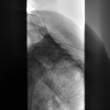
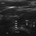
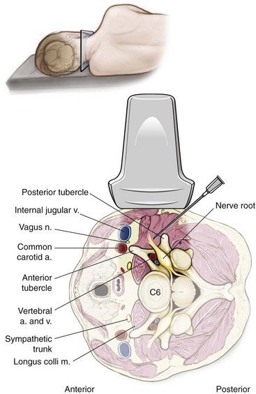
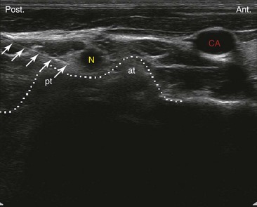
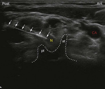
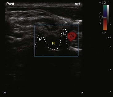
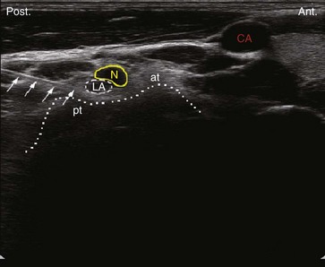
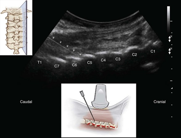
Ultrasound examination is usually performed using a high-resolution linear array transducer in the lateral decubitus position. The transducer is applied transversely to the lateral aspect of the neck to obtain a short-axis view of the cervical spine (Fig. 21-1). The cervical transverse process can be easily identified with the anterior and posterior tubercles as hyperechoic structures “two-humped camel” sign, and the hypoechoic round to oval nerve root in between (Fig. 21-2).9 First, the correct cervical level needs to be determined by identifying the transverse process of the seventh and sixth cervical vertebrae (C7 and C6). The seventh cervical transverse process (C7) differs from the above levels because it usually has a rudimentary anterior tubercle and one prominent posterior tubercle.10 Then by moving the transducer cranially, the transverse process of the sixth cervical spine comes into the image with the characteristic sharp anterior tubercle (Fig. 21-3), and then the consecutive cervical spinal level can be easily identified. To confirm the correct spinal level, the vertebral artery can be followed as well. The vertebral artery runs anteriorly at the C7 level before it enters the foramen of the C6 transverse process in about 90% of cases. However, it enters at C5 or higher in the remaining cases (Fig. 21-4).11
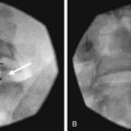
After the appropriate spinal level has been identified, a 22-gauge blunt-tip needle can be introduced just lateral to the lateral end of the transducer and advanced in plane from posterior to anterior under real-time ultrasound guidance to target the corresponding cervical nerve root at the external foraminal opening between the anterior and posterior tubercles of the transverse process, which can be easily identified as the “two-humped camel” sign. One can successfully monitor the spread of the injectate around the cervical nerve with real-time ultrasonography; the absence of such spread around the nerve root may suggest unsuspected or inadvertent intravascular injection (Fig. 21-5). However, it should be mentioned here that is difficult to monitor the spread of the injectate through the foramen into the epidural space (because of the bony drop-out artifact of the transverse process). This is the reason behind referring to this approach as a “cervical selective nerve root block” rather than cervical transforaminal epidural injection.
The author believes that visualization of small vessels (radicular arteries) may be very challenging, especially in obese patients, and requires special training and expertise. Ultrasonography should be used in conjunction with real-time fluoroscopy with contrast injection and digital subtraction (when available) to confirm safe needle placement.2
Cervical Medial Branch and Facet Joint Injections
Anatomy
Cervical zygapophyseal (facet) joints are diarthrodial joints formed by the superior articular process of one cervical vertebra articulating with the inferior articular process of the vertebrae above at the level of the junction of the lamina and the pedicle. The angulation of the facet joint increases caudally, being about 45 degrees superior to the transverse plane at the upper cervical level to assuming a more vertical position at the upper thoracic level. The superior articular process also faces more posteromedially at the upper cervical level, and this changes to more posterolateral at the lower cervical level, with C6 being the most common transition level.12,13
Each facet joint has a fibrous capsule and is lined by a synovial membrane. The joint also contains varying amounts of adipose and fibrous tissue forming different types of synovial folds contributing to different pathophysiology for joint dysfunction.14
The cervical zygapophyseal joints are innervated by articular branches derived from the medial branches of the cervical dorsal rami. The C4-C8 dorsal rami arise from their respective spinal nerves and pass dorsally over the root of their corresponding transverse processes. The medial branches of the cervical dorsal rami curve medially around the corresponding articular pillars and have a constant relationship to the bone at the dorsolateral aspect of the articular pillar as they are bound to the periosteum by an investing fascia and held in place by the tendon of the semispinalis capitis muscle.15
The articular branches arise as the nerve approaches the posterior aspect of the articular pillar, one innervating the zygapophyseal joint above and the other innervating the joint below. Consequently, each typical cervical zygapophyseal joint has dual innervation, from the medial branch above and below its location.15
The medial branches of the C3 dorsal ramus differ in their anatomy. A deep medial branch passes around the waist of the C3 articular pillar similar to other typical medial branches and supplies the C3-C4 zygapophyseal joint. The superficial medial branch of C3 is large and known as the third occipital nerve (TON). It curves around the lateral and then the posterior aspect of the C2-C3 zygapophyseal joint, giving articular branches to the joint. Articular branches may also arise from a communicating loop that crosses the back of the joint between the TON and the C2 dorsal ramus. Beyond the C2-C3 zygapophyseal joint, the TON becomes cutaneous over the suboccipital region. So pain derived from the C2-C3 zygapophyseal joint can be addressed by blocking the ipsilateral TON as it crosses the lateral aspect of the joint, and pain derived from joints below C2-C3 can be addressed by blocking the cervical medial branches as they pass around the waists of the articular pillars above and below the corresponding joint.16
Literature Review of Ultrasound-Guided Third Occipital Nerve and Cervical Medial Branch Block
Eichenberger et al17 reported ultrasound-guided TON blockade in volunteers. The TON was visualized in all volunteers and showed a median diameter of 2.0 mm. The C2-C3 facet joint was identified correctly by ultrasonography in 27 of 28 cases, and 23 needles were placed correctly into the target zone. They defined the radiologic target point arbitrarily as the intersection of a vertical line passing through the middle of the C2-C3 zygapophyseal joint and an oblique line passing directly over the joint line. They reported accuracy of needle position as confirmed by fluoroscopy in 82% of insertions and a 90% success of nerve blockade.
Although they reported in the above study the feasibility of identifying the medial branch of C3, there have been no other feasibility studies regarding ultrasound-guided lower cervical medial branch block. Nevertheless, the technique was reported before.18,19
Literature Review of Ultrasound-Guided Cervical Facet Intraarticular Injections
Galiano et al20 studied the feasibility of ultrasound-guided cervical facet joint intraarticular injections in cadavers using a lateral approach. They were able to accurately identify the facet joints from C2-C3 to C6-C7 in 36 of 40 attempts. All needle tips were located inside the joint space as verified by CT. Subsequently, they have studied and advocated the use of an ultrasound-guided CT-assisted navigation system as a teaching tool for performing facet injections.21
Sonoanatomy and Ultrasound-Guided Technique for Cervical Facet Intraarticular Injections
The author prefers the posterior approach because it is easier to identify the correct cervical level while the patient is in the prone position. Counting can be started from cranial to caudal. (The C1 spine has no or rudimentary spinous process, and the first identified bifid spinous process belongs to C2.) Another advantage of this approach is that the needle is advanced in a caudal to cranial direction, and this matches the caudal angulation of the cervical facet joint, making it easier for the needle to get into the joint space atraumatically. Also, bilateral injections can be performed without the need for position change.22
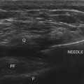
A linear or a curved transducer may be used depending on the size of the patient. A longitudinal scan is obtained initially at the midline (spinous process), and then by scanning laterally, one can easily see the lamina; farther laterally, the facet column appears in the image as the characteristic “saw sign” (Fig. 21-6). If in doubt, one can scan even more laterally until the facet joists are no longer in the image and then come back medially toward the facet joints. The inferior articular processes of the level above and the superior articular process of the level below appear as a hyperechoic signals, and the joint space appears as an anechoic gap in between. The needle is then inserted inferior to the caudal end of the transducer and advanced from caudad to cephalad in plane to enter the inferior part of the joint under real-time ultrasonography (see Fig. 21-6).
Sonoanatomy and Ultrasound-Guided Technique for Third Occipital Nerve and Cervical Medial Branch Block
Eichenberger et al17 described the technique in details. The patient is placed in the lateral position, and a high-frequency linear transducer is applied just caudal to the mastoid process exactly perpendicular to the lateral aspect of the neck in a transverse plane to obtain a short-axis view.
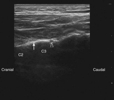
The needle is introduced from immediately below the ultrasound probe and advanced perpendicular to the beam (out of plane) under ultrasound guidance toward the apex of the convexity of the joint until bony resistance was encountered. Then the transducer is rotated to the longitudinal plane because in this view the nerve is best visualized. The TON is identified with the typical sonomorphological appearance of a small peripheral nerve just lateral to the C2-C3 joint, and the needle is adjusted as needed to lie closer to the nerve (Fig. 21-7).
Cervical Medial Branch Block
Lateral Approach
The patient is placed in the lateral position, and a high-frequency linear transducer is applied longitudinally with its upper end just below the mastoid process to obtain a longitudinal view of the cervical spine. After the C2-C3 joint is identified as above, the transducer is slowly moved in a caudal direction to view the lower facet joints until the desired level of the cervical facet joint is reached. The highest points in the bony reflex of the articular pillars represent the facet articulations, and the medial branches can be visualized at the deepest point over the articular pillars between the two articulations in contrast to the TON which runs over the highest point of the articulation.17
The needle can be introduced just caudal to the ultrasound transducer and advanced under real-time ultrasonography to the target nerve (in plane). Alternatively, after the correct level has been identified, the transducer is rotated to obtain a short-axis view, and the needle is advanced perpendicular to the beam (out of plane) under ultrasound guidance toward the articular pillar until bony resistance is encountered. Then the transducer can be rotated to the longitudinal plane because the nerve is better visualized in this view, and the needle is adjusted as needed to lie closer to the nerve in the same manner described above for the TON block (see Fig. 21-7).17
1 Narouze SN, editor. Atlas of ultrasound-guided procedures in interventional pain management, ed 1, New York: Springer, 2011.
2 Narouze S. Ultrasound-guided Interventional procedures in pain management: evidence based medicine. Reg Anesth Pain Med. 2010;35(suppl):S55-S58.
3 Rathmell JP, Aprill C, Bogduk N. Cervical transforaminal injection of steroids. Anesthesiology. 2004;100:1595-1600.
4 Huntoon MA. Anatomy of the cervical intervertebral foramina: vulnerable arteries and ischemic neurologic injuries after transforaminal epidural injections. Pain. 2005;117:104-111.
5 Tiso RL, Cutler T, Catania JA, et al. Adverse central nervous system sequelae after selective transforaminal block: the role of corticosteroids. Spine J. 2004;4:468-474.
6 Baker R, Dreyfuss P, Mercer S, et al. Cervical transforaminal injections of corticosteroids into a radicular artery: a possible mechanism for spinal cord injury. Pain. 2003;103:211-215.
7 Galiano K, Obwegeser AA, Bodner G, et al. Ultrasound-guided periradicular injections in the middle to lower cervical spine: an imaging study of a new approach. Reg Anesth Pain Med. 2005;30:391-396.
8 Narouze SN. Ultrasound-guided cervical periradicular injection: cautious optimism [letter]. Reg Anesth Pain Med. 2006;31:87.
9 Narouze S, Vydyanathan A, Kapural L, et al. Ultrasound-guided cervical selective nerve root block: a fluoroscopy-controlled feasibility study. Reg Anesth Pain Med. 2009;34:343-348.
10 Martinoli C, Bianchi S, Santacroce E, et al. Brachial plexus sonography: a technique for assessing the root level. AJR Am J Roentgenol. 2002;179:699-702.
11 Matula C, Trattnig S, Tschabitscher M, et al. The course of the prevertebral segment of the vertebral artery: anatomy and clinical significance. Surg Neurol. 1997;48:125-131.
12 Pal GP, Routal RV, Saggu SK. The orientation of the articular facets of the zygapophyseal joints at the cervical and upper thoracic region. J Anat. 2001;198:431-441.
13 Yoganandan N, Knowles SA, Maiman DJ, et al. Anatomic study of the morphology of human cervical facet joint. Spine. 2003;28:2317-2323.
14 Inami S, Kaneoka K, Hayashi K, et al. Types of synovial fold in the cervical facet joint. J Orthop Sci. 2000;5:475-480.
15 Bogduk N. The clinical anatomy of the cervical dorsal rami. Spine. 1982;7:319-330.
16 Lord SM, Barnsley L, Bogduk N. Percutaneous radiofrequency neurotomy in the treatment of cervical zygapophysial joint pain: a caution. Neurosurgery. 1995;36:732-739.
17 Eichenberger U, Greher M, Kapral S, et al. Sonographic visualization and ultrasound-guided block of the third occipital nerve: prospective for a new method to diagnose C2-C3 zygapophysial joint pain. Anesthesiology. 2006;104:303-308.
18 Gofeld M. Ultrasonography in pain medicine: a critical review. Pain Pract. 2008;8:226-240.
19 Siegenthaler A, Narouze S, Eichenberger U. Ultrasound-guided third occipital nerve and cervical medial branch nerve blocks. Tech Reg Anesth Pain Manage. 2009;13(3):128-132.
20 Galiano K, Obwegeser AA, Bodner G, et al. Ultrasound-guided facet joint injections in the middle to lower cervical spine: a CT-controlled sonoanatomic study. Clin J Pain. 2006;22:538-543.
21 Galiano K, Obwegeser AA, Bale R, et al. Ultrasound-guided and CT-navigation-assisted periradicular and facet joint injections in the lumbar and cervical spine: a new teaching tool to recognize the sonoanatomic pattern. Reg Anesth Pain Med. 2007;32:254-257.
22 Narouze S. Ultrasound guided cervical facet intraarticular injections. Tech Reg Anesth Pain Manage. 2009;13(3):133-136.