Chapter 38 Thoracolumbar Junction Stabilization
ANTERIOR STABILIZATION
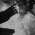
The use of spinal instrumentation for anterior column reconstruction is known to improve fusion rates and provide immediate stability at the thoracolumbar junction. Anterior instrumentation for the thoracolumbar spine was first applied by Dwyer and colleagues for the correction of scoliosis, using the cable and screw system.1 Zielke and colleagues modified the Dwyer system by substituting a 3.2-mm single threaded rod with nuts for the cable.2 Kostuik has reported the anterior spinal fixation system using a Dwyer-Hall vertebral plate and Harrington distraction rod (anterior Kostuik-Harrington system) in the treatment of spinal fracture3 (Fig. 38-1).
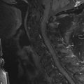
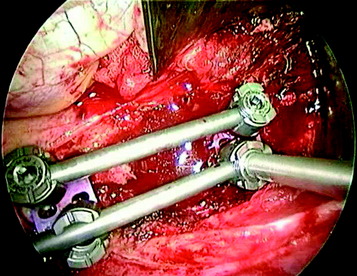
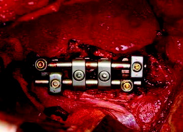
Kaneda and co-workers developed a technique of spiked vertebral plates attached to vertebral bodies via screws interconnected by rigid rods. The Kaneda Smooth Rod Spine System (Kaneda SR™; DePuy Spine, Raynham, MA) consists of rods and four constrained bicortical screws that allow compression and distraction (Fig. 38-2).
OPTIONS IN ANTERIOR FIXATION OF THORACOLUMBAR JUNCTION
SCREW-ROD SYSTEM
Tumor Removal (Corpectomy) and Graft Insertion
The discs and endplate material rostral and caudal to the tumor are removed. The removal of the tumor-infiltrated vertebral body is performed. The posterior cortex of the vertebral body is removed, and the ventral dura should be visible. After corpectomy, the width of the vertebral bodies above and below the corpectomy site is measured using the depth gauge. This value can be used as a guide to select the correct screw length to achieve bicortical fixation. As a general rule, anterior screws are typically 5 mm shorter than posterior screws. The selected vertebral body spacer with bone graft is replaced. A titanium mesh cage with a larger diameter and/or augmentation of the internal end ring produces a significant increase of the interface strength between the cage and the vertebra.4
Staple Placement
The selected staples are fixed into the proper position on the vertebral body (Fig. 38-3). The center spike enables the surgeon to create a firm attachment.
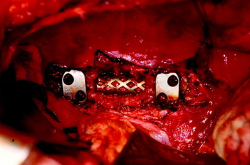
Fig. 38-3 Staple placement after graft insertion. Anterior slots are kept farther apart than posterior slots.
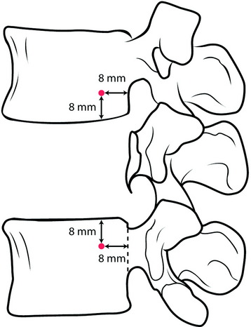
When placed, the staples should be oriented on the spine so that the anterior screw holes are farther apart than the posterior screw holes. The location of the posterior hole is 8 mm apart from the posterior cortical margin and from the adjacent endplate (Fig. 38-4).
Screw Insertion
The awl may be used to create the pilot screw hole. The awl will create a 15-mm deep channel into the bone to guide the tap and screw. Following the awl’s path, the tapping screw is inserted (Fig. 38-5). The anterior and posterior screws’ trajectory should be arranged in a convergent fashion. The converging angle between them is about 8 degrees. On the coronal plane, they should be arrayed in parallel with the adjacent endplate. For maximum rigidity in an anterior spinal construct, the ideal device is one that provides graft compression by means of four bicortical screws constrained to the rods. Anterior screws may fail to bear axial loads effectively because of parallelogram translational deformation. A simple convergent insertion of the screws should prevent construct failure of this mechanism. Screws should be inserted until the screw head comes into contact with the staple. Screw openings should be parallel to the spine to allow for insertion of the rods. In principle, the screw is positioned for the bicortical purchase. Bicortical screws are significantly stronger in resisting pullout than are unicortical screws (Fig. 38-6). Advancing an anterior vertebral body screw to engage the second cortex increases resistance to pullout by 25–44%, depending on vertebral bone mineral density.5
Rod Placement and Tightening
The rod is laid down on the screw head, and the rostral screw is locked with the rod stabilizer and tightening torque wrench to 80-inch pounds (Fig. 38-7). The caudal set-screws remain loose for compression of the construct. If the construct has a load-sharing capacity, the implant construct requires short fixed or applied moment arm cantilever beam constructs. The implant construct also should be in a compression mode, which causes the load to be shared between the graft and the implant construct. While the compression force is applied to the caudal screw, the set-screw is locked with a tightener.
Cross Connector Application
Cross connectors are applied and tightened to 80-inch pounds. Two cross connectors are recommended for each construct (Fig. 38-8). Rigid cross-fixation of the rod on each side to its counterpart can prevent translational deformity. Two cross connectors create a quadrilateral frame construct. This resists torsional deformation of the rods. Three or more cross-links offer no significant advantage over two. In general, the two cross-links should be placed roughly at the junctions of the middle third of the construct with the two terminal thirds of the construct.
SCREW-PLATE SYSTEM
The screw-plate system is composed of posterior cancellous bolts, anterior cancellous locking screws, and a thoracolumbar plate.6 The plating system is known to be comparable to the dual rod-screw system in load sharing and stiffer in flexion/extension and lateral bending.
Posterior Bolt Placement
The posterior bolt should be placed either parallel to the posterior longitudinal ligament or directed from a posterior to anterior direction to prevent violation of the spinal canal (Fig. 38-9).
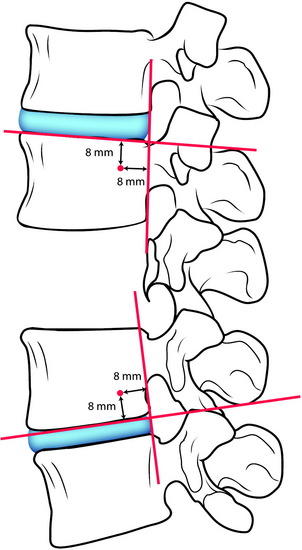
Plate Placement and Locking
The ideal plate should extend within a few millimeters of the cranial and caudal endplates without violating the adjacent discs (Fig. 38-10). After grafting is completed, the plate is inserted over the bolt posts with the scallop directed posteriorly. With a left-sided approach, the caudal bolt should be placed into the longer slot in the plate. This arrangement is reversed for a right-sided approach. The cephalad outer nut is tightened onto the bolt, and the caudal outer nut is then tightened into the compressed position.
Anterior Screw Placement
The anterior screws are applied unicortically or bicortically. An appropriate-length 6-mm screw is then inserted and locked into the plate. The screw should be directed parallel to the endplate and convergent with the posterior bolt. The slots on the plate are designed with 8 degrees of convergence between the bolt and screw (Fig. 38-11). This can result in the actual convergence angle measuring more than 10 degrees.
CASE ILLUSTRATION
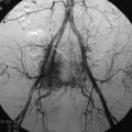
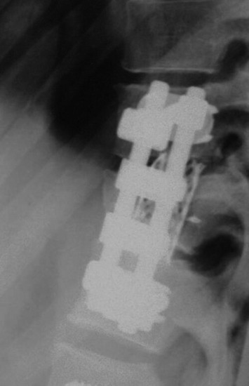
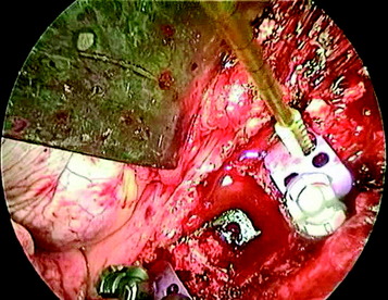
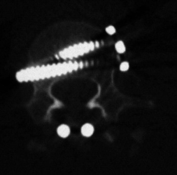
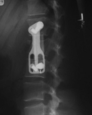
A case of T12 metastasis of breast cancer is presented. The lesion was confined to the vertebral body, and endoscopic corpectomy was performed (Fig. 38-13). Postoperatively, the vertebral body replacement (VBR) cage was inserted and a screw-plate system was implanted. Two screws were seen to be convergent (Fig. 38-14).
POSTERIOR STABILIZATION IN THORACOLUMBAR JUNCTION
In the case of a one-level corpectomy, the extent of the posterior fixation can be limited to one level above and one level below if anterior stabilization also is performed. This can be adjusted depending on the preoperative kyphotic angle. It should be remembered that the thoracolumbar junction is normally straight, with thoracic kyphosis and lumbar lordosis beginning at T10 and L2. Kyphosis has a profound impact on the biomechanical behavior of long-segment posterior spinal constructs according to Euler’s formula for loading of curved long columns. Using the same posterior hook system, as the kyphotic angle is increasing, the construct stiffness decreases. Going from straight alignment to 53 degrees decreases the stiffness 59.6%. The biomechanical stiffness of the straight spine is sensitive to both an increase in hook fixation sites and an increase in rod diameter. The kyphotic spine, however, is more sensitive to variations in rod diameter. With increasing kyphosis, the optimum instrumentation strategy will maximize both the rod diameter and the number of hook sites.7
SEVERAL OPTIONS FOR T12 VERTEBRAL BODY TUMOR
HOOK AND SCREW CONSTRUCT
After T12 corpectomy and anterior stabilization are performed, long-segment posterior stabilization is accomplished with a hook and pedicle screw system (Fig. 38-15). Pedicle hooks are applied to the T9, T10 pedicles and the transverse process hook is applied to the T8 level. The L2 and L3 levels are fixed with pedicle screws. An offset hook is necessary to connect the hook and screw because the screws tend to carry the rods laterally.8

SCREW CONSTRUCT
For the stiff construct, the pedicle screws also are fixed to the lower thoracic spine (Fig. 38-16). The hole is tapped and probed to ensure that the canal has not been entered and that the lateral pedicular cortex has not been violated. In addition to following the axis of the pedicle, the screws are directed slightly medially to triangulate with the opposite side. This maneuver increases the resistance to pullout.
CASE ILLUSTRATION
STABILIZATION AFTER TOTAL SPONDYLECTOMY OF L1
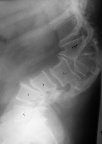
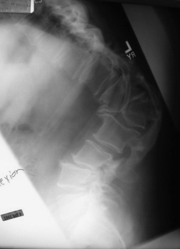
This case showed post-traumatic kyphosis at the thoracolumbar junction. Preoperative x-ray showed severe kyphotic deformity and wedge compression at the L1 vertebral body. On flexion and extension lateral views, a kyphotic angle change was not seen (Figs. 38-17 and 38-18).
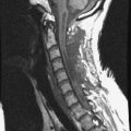
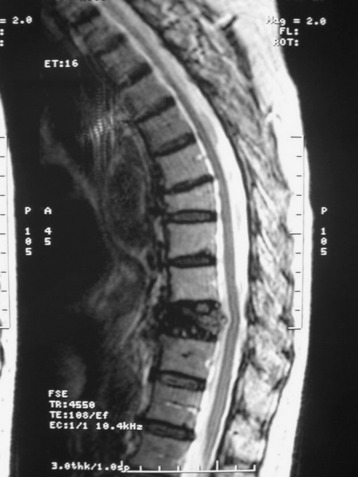
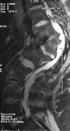
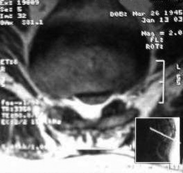
On magnetic resonance imaging (MRI), spinal canal encroachment was seen and neural compression was expected (Figs. 38-19 and 38-20). For sufficient correction, the vertebral body and posterior element had to be removed totally.
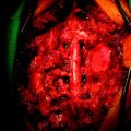
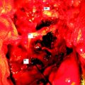
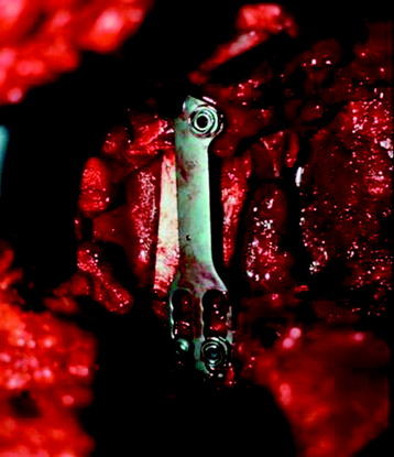
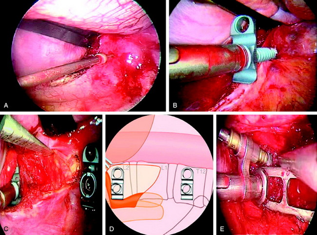
The posterior approach was performed first. All the posterior elements, including laminae, facet, and spinous process, were removed at the pedicle. Pedicle screws were inserted into the T11, T12, L2, and L3 levels (Fig. 38-21). The posterior wound was closed with the rod unconnected. As a subsequent procedure, L1 vertebral body resection was performed with a thoracoscopic approach from the left side. After diaphragmatic detachment, the operative field was extended to the L2 level. Using a drill and osteotome, the L1 vertebral body was totally removed. Then the VBR cage was inserted. Circumferential decompression was achieved, and the kyphotic deformity was easily corrected as the height of the VBR cage increased. After a sufficient reduction was achieved, anterior instrumentation was performed with Modular Anterior Construct System for Thoracolumbar Spine (MACS-TL) endoscopically. As a third procedure, the posterior wound was reopened. The rods were applied to the screws that had already been inserted.
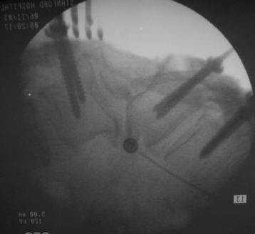
Fig. 38-21 Using a posterior approach, the posterior elements were removed, and pedicle screws were inserted.
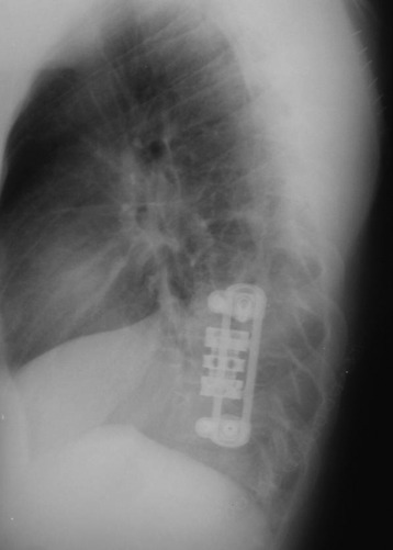
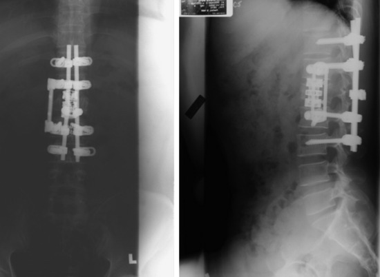
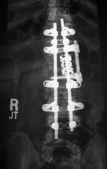
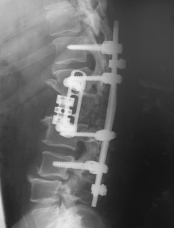
Postoperatively, all of the bony structures disappeared from the L1 level. Bony fusion was performed posterolaterally (Fig. 38-22). Posteriorly two levels above and two levels below, pedicle screw fixation was performed (Fig. 38-23).
In a biomechanical study, only circumferential instrumentation techniques exhibited greater stiffness than the intact spine in all loading modes. Short circumferential fixation provided more stability than did multilevel posterior instrumentation. Multilevel posterior fixation provided more stiffness than did short posterior and anterior instrumentation alone. From a biomechanical viewpoint, neither short posterior nor anterior instrumentation alone should be selected after total spondylectomy.9 In cases in which the unilateral facet is intact, anterior stabilization with the Kaneda SR system and anterior strut grafting achieved equivalent stability to circumferential instrumentation.