[level-membership-for-anesthesiology-category]
Chapter 1 The supply of anaesthetic and other medical gasses
Properties of medical gasses
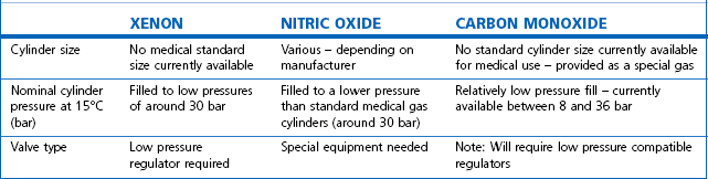
The properties of some of the common medical gasses are summarized in Table 1.1. The newer gasses and their potential therapeutic indications are briefly discussed below.
Table 1.1 Physical properties of common pressurized gasses
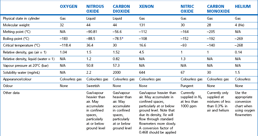
N/A, not applicable. * Sublimation.
Note: all values STP. Mixed gasses, e.g. Heliox, will have different physical properties. For exact values, please contact the manufacturer.
Details of carbogen (5% CO2 + 95% O2), lung function gasses, medical gasses for laser surgery and other agents not listed here are available from the manufacturers. Extensive information on the properties of all gasses and data sheets containing up-to-date product information can be obtained from the BOC Medical Gasses website www.bocmedical.com.
Heliox
• It has a lower density than air (0.42 kg/m3 vs 1.22 kg/m3 at 15°C and 1 atm) and hence a lower Reynolds number in any given situation, resulting in a higher likelihood of laminar gas flow characteristics.
• It has a higher thermal conductivity than air, which is of significance when its gas flow measurement is based on this principle (see Chapter 2, Hot wire anemometry).
Medical gas cylinders
Modern cylinders are manufactured using lightweight strong chrome-molybdenum steels which, as well as conforming to stringent material standards, can be filled to pressures of up to 300 bar g (where (g) denotes gauge pressure; see Chapter 2). Cylinders were previously made of the much heavier low-carbon steels: few of these are in circulation any longer in the UK.
Cylinder sizes
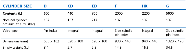
Technically, cylinders are defined by their water capacity and range between 1.2 L and 47.2 L, and are identified by a size code ranging from C to J (Fig. 1.1). This notation incorporates a pressure aspect to give an indication of available gas volume. Tables 1.2–1.7 give details for oxygen, nitrous oxide, Entonox, carbon dioxide, Heliox21, xenon, nitric oxide and carbon monoxide cylinders.
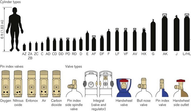
Figure 1.1 Cylinder types and sizes, valves types and pin index valves.
(from BOC Medical, with permission).
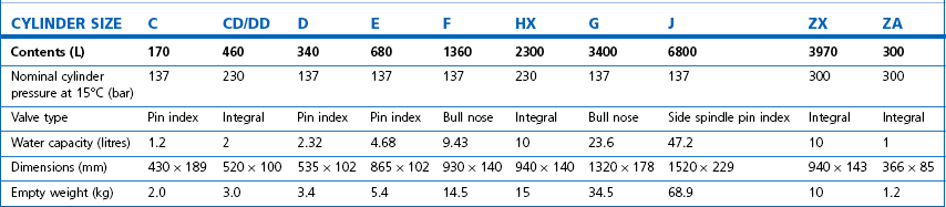
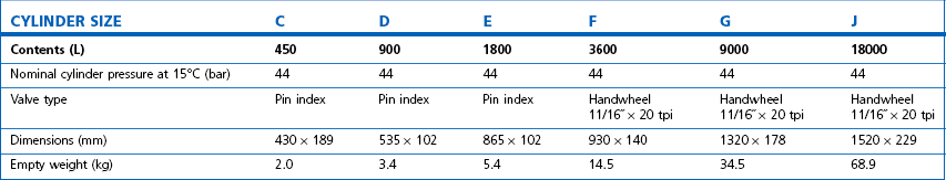
Table 1.4 Relative sizes and specifications of commonly used Entonox cylinders
Entonox, a mixture of 50% oxygen and 50% nitrous oxide, exists as a gas. The pseudo critical temperature of Entonox in pipelines at 4.1 bar is below −30°C. Nitrous oxide in an Entonox cylinder, however, begins to separate out from Entonox if the temperature falls below −6°C. A homogenous mixture is again obtained when the temperature is raised above 10°C and the cylinder is agitated.
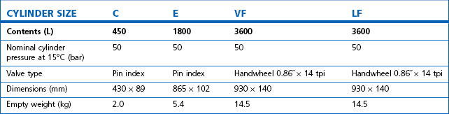
Table 1.6 Relative sizes and specifications of commonly used Heliox21 cylinders
| CYLINDER SIZE | HL | HX |
|---|---|---|
| Contents (L) | 8200 | 1780 |
| Nominal cylinder pressure at 15°C (bar) | 200 | 200 |
| Valve type | Side outlet | Integral |
| Dimensions (mm) | 1540 × 230 | 940 × 140 |
| Empty weight (kg) | 50 | 15.5 |
Cylinder filling and maintenance
Most gasses such as oxygen, medical air, helium and Heliox21 are stored in cylinders in a compressed gaseous state and are normally filled by pressure. Nitrous oxide and carbon dioxide, however, are liquefied gasses under pressure. The liquid is in equilibrium with the gas, the pressure being dependent on the temperature. These gasses are charged by weight and not by pressure. The maximum weight of gas filled into the cylinder divided by the weight of water that would completely fill the cylinder is called the maximum filling ratio and is governed by legislation. This ‘fill ratio’, termed ‘fill density’ elsewhere, is critical. In the UK this value is 0.75 at 15.5°C for nitrous oxide and carbon dioxide. Note that due to the difference in the densities of liquefied gasses and water this ratio is not the same as the proportion of the volume of the cylinder filled by the liquid phase, which is nearer 90 to 95% for nitrous oxide. If there is insufficient gas space left in the cylinder after filling, a comparatively small increase in temperature will cause a significant increase in pressure and could, in extreme circumstances, cause the cylinder to rupture.
Some applications require carbon dioxide in liquid form. This is supplied using cylinders fitted with a ‘dip tube’ connected to the cylinder valve, which allows liquid from the bottom of the cylinder to be drawn up through the valve (Fig. 1.2). These cylinders, supplied in F size and known as LF, have a white stripe down the length of the cylinder body. For other CO2 applications where vapour is required, VF cylinders should be used. It is important to ensure that the correct cylinder is used to prevent damage to equipment.
Cylinder identification
The correct method of identifying the contents of a cylinder is to read the collar identification label (rather than assuming that the colour of the cylinder or the type of valve fitted reliably indicates gas inside it). The label (Fig. 1.3) is a legal requirement and contains all the key information for the user:
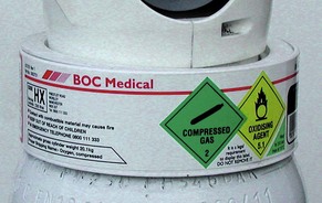
• product name, chemical symbol and pharmaceutical form of the product
• directions for use and information for storage and handling.
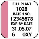
The cylinder label also has a unique batch label (Fig. 1.4), which contains: the batch number; fill and expiry date; and the size and type of gas. The label is changed every time the cylinder is filled and serves two important functions: (a) it provides vital information for a batch recall should the cylinder be involved in an incident; and (b) it provides information for proper cylinder rotation.
Cylinder testing
All cylinders must undergo hydraulic testing and internal inspection at regular intervals, to ensure they remain safe to use. The test is carried out every 10 years for steel cylinders and every 5 years for composite cylinders. A colour-coded plastic ring between the valve and the cylinder neck indicates when the next test date is due. In general, cylinders have a long service life and tend to be withdrawn for reasons of technical obsolescence rather than deterioration per se.
Colour coding
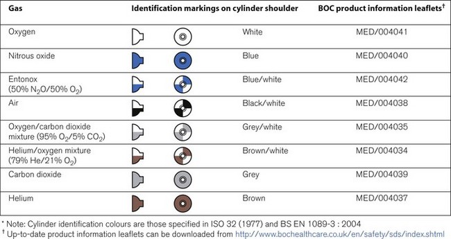
Medical cylinders in the UK conform to colour codes specified in ISO 32:1972 and EN 1089-3. The colour coding relates only to the shoulder of the cylinder. Figure 1.5 shows the colour codes for medical gas cylinders in the UK.
Cylinder valves
Medical cylinder valves can generally be categorized as follows:
• Non-integral valves (which require manual attachment of an external pressure regulator):


• Integral valves (which have a built in regulator and possibly flowmeter).
Pin index system
Small pin index valves (Fig. 1.6) are fitted to small cylinders (less than 5 litre capacity) which are commonly connected directly to medical equipment such as anaesthetic machines. Newer designs using a thumbwheel do away with the need for a spanner to operate the valve.
Side spindle pin index valves (Fig. 1.6) These are fitted to large cylinders of medical oxygen, medical air, Entonox used in pipeline manifolds and F size Entonox cylinders.
Both types of pin index valves conform to BS EN ISO 407:2004 and adopt an indexed outlet system which incorporates a gas-specific combination of holes positioned to correspond to pins located on the receiving equipment, making it impossible to connect the cylinder to an incorrect gas connection. Fig. 1.1 shows the different pin positions. The pin index system also prevents charging with the wrong gas, as the gas suppliers use the same non-interconnectable system for their filling connections.
Pin index cylinders require a washer (seal) between the face of the cylinder valve outlet and the equipment to which it is fitted. This bonded non-combustible seal, known as a ‘Bodok’ washer (Figs 1.7 and 1.8), must be kept clean and should never become contaminated with oil or grease. If a gas tight seal cannot be achieved by moderate tightening of the screw clamp, it is recommended that the seal be renewed. Excessive force should never be used.

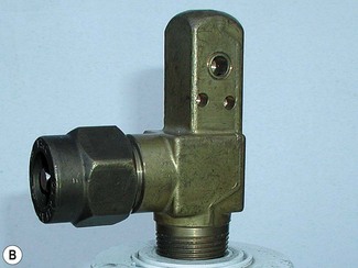
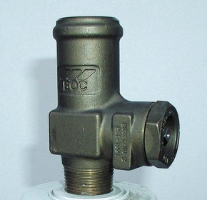
Bull nose outlet valve
This type of valve (Fig. 1.9) is fitted to F and G size cylinders including medical oxygen, medical air, helium, and mixed gasses such as carbogen and Heliox. The valve is spindle key operated and has a 5/8-inch female outlet thread into which a regulator is fitted. The spindle mechanism is assembled in two parts. This permits a gas tight seal to be achieved without the use of excessive force and increases its operational life.
All bull nose valves are fitted with an RP (residual pressure) device, to ensure that a positive pressure of approximately 3 bar is retained in the cylinder (Fig. 1.10). This prevents the ingress of moisture should the valve be left open when the cylinder is empty. When connecting regulator equipment to the valve, the user should always adopt the proper connecting procedure:
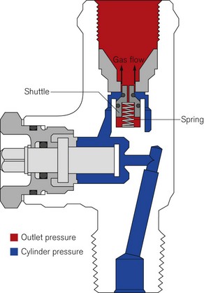
Figure 1.10 Schematic showing ‘residual pressure’ device of a bull nose cylinder valve.
Redrawn using material kindly provided by Müller Gas Equipment A/S, Denmark.
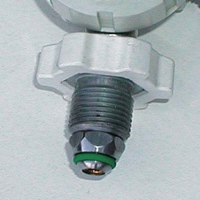
• Ensure the ‘O’ ring (Fig. 1.11) fitted to the regulator is in good condition and hand tighten the regulator only.
• Once fitted, open the spindle valve slowly (to prevent a gas surge) at least one full turn and note the position of the regulator gauge needle.
• A simple test for leaks can be carried out by closing the cylinder spindle valve and noting any drop in pressure shown on the gauge. If a leak does exist, spraying the joints with a leak detection spray will identify it. If a leak is evident at the valve outlet, replace the ‘O’ ring and repeat the procedure. If the leak persists, fit a replacement regulator. (Note: It is vitally important that any leak detection spray has been approved by the cylinder supplier as being compatible with their equipment and the gas.)
• When changing an empty cylinder, close the cylinder valve and vent the regulator completely before attempting to disconnect it.
Handwheel valves
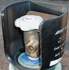
Large nitrous oxide cylinders for use on cylinder manifolds and carbon dioxide cylinders of size F and G are fitted with handwheel valves which are surrounded by a protective guard (Fig. 1.12), and have a gas specific, male thread, side outlet.
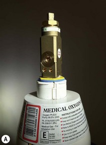
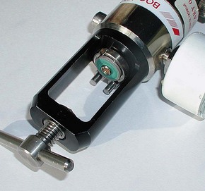
Integral valves
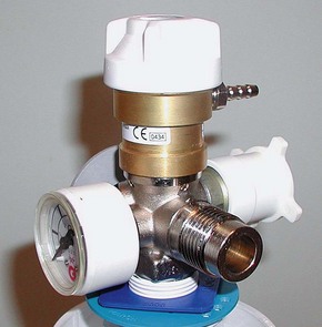
The introduction of integral valves (Fig. 1.13), which have their own built-in regulator, has revolutionized the industry by greatly improving safety and eliminating the need for regulator maintenance by hospitals. They have a number of advantages:
• The regulator assembly is manufactured in a clean environment and is much less prone to particulate contamination.
• The built-in regulator eliminates the risk of incorrect regulator attachment which could result in damage to lower-pressure rated equipment.
• The valves are surrounded by guards which reduce the risk of damage and ease manual handling of the cylinder.
• They are considerably easier to use and have live pressure gauges built in for checking cylinder contents.
• The valves possess two outlets – a variable flow outlet (via a fir tree connector) and a fixed pressure outlet to connect equipment requiring a static driving pressure.
A commonly encountered version of the integral valve has a combination of a clickstop flowmeter giving 0–15 l min−1 in stepped increments and a female BS Schraeder connection at 4 bar g to provide high pressure gas. This type of valve is currently fitted to cylinders of up to 10 l water capacity. Care must be taken to ensure that the flowmeter selector dial is not ‘parked’ between click stops as this will result in a cessation of gas flow.
Storage of medical gas cylinders
• be under cover (preferably inside) and not subjected to extremes of heat
• be kept dry, clean and well ventilated
• have good access for deliveries and a reasonably level floor surface
• allow segregation of ‘full’ and ‘empty’ cylinders
• permit separation of different gasses and cylinder sizes
• allow for strict stock rotation to enable cylinders with the oldest fill date to be used first
• be sited away from storage areas containing combustible materials or sources of heat or ignition
• have warning notices clearly posted prohibiting smoking or naked lights in the vicinity
• allow for large cylinders to be stored vertically in concrete pens and small cylinders to be stored horizontally in wooden or plastic racks to prevent damage to the cylinders
• not allow the temperature to fall below 10°C where full Entonox cylinders are stored
Cylinder manifolds
The typical configuration consists of two equal banks of gas cylinders (one demarcated duty and one stand-by). These are arranged around a central control panel and provide a nominal output pressure of 4 bar (7 bar for surgical air). The change over from the ‘duty’ to ‘stand-by’ banks is normally automatic. The installation should also contain a manually operated reserve of at least two cylinders (Fig. 1.14) also stored in the manifold room. Any additional cylinders should be held in the general medical gas store.
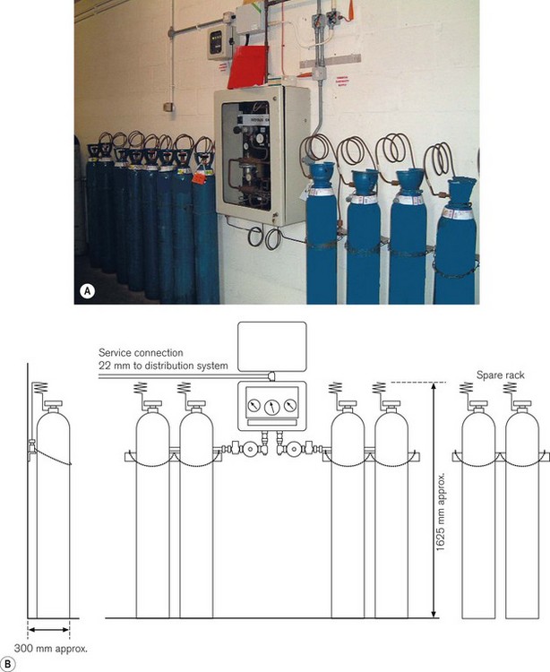
Table 1.8 gives nominal and usable capacities of cylinders commonly used on manifolds.
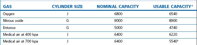
* The usable figures are based on a residual pressure of 7 bar in the cylinders († 15 bar residual pressure).
• a yellow ‘duty bank empty, stand-by running’ condition
• a yellow ‘duty bank empty, stand-by low’ condition
Safety precautions
• be constructed from a fireproof material – either brick or concrete
• have ventilation at the top and bottom to permit the circulation of air
• ideally be located to enable a delivery vehicle access to prevent manhandling cylinders long distances
• be temperature controlled between 10 and 40°C. This is especially important in the case of an Entonox manifold as nitrous oxide and oxygen can separate out at temperatures below −6°C. It is advisable to let the cylinders stand for 24 hours in a temperature of more than 10°C before fitting them to the manifold
• only contain cylinders for use on the pipeline(s) located in the manifold room
• not be used as a general store
• have sufficient warning signs on the outside and inside of the building.
Bulk oxygen supply systems
• without the labour-intensive distribution associated with compressed gas cylinders
• with greater on site storage capacity (at 15°C, one volume of liquid oxygen gives 842 times its volume compared with a manifold cylinder which delivers only 137 times its volume)
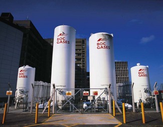
Cryogenic liquid system (CLS)
• an insulated cryogenic storage vessel to store the bulk liquid oxygen
• an ambient heated vaporizer to convert the cryogenic liquid oxygen into a gas for supply to patients via a pipeline distribution system
• a control panel to control the pressure and flow of gas to the pipeline
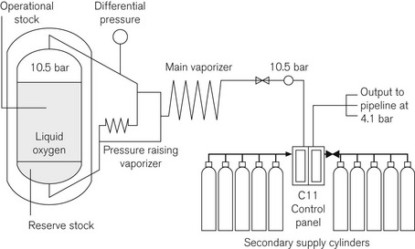
• a single vessel containing operational stock with a cylinder manifold containing the secondary supply. Fig. 1.15 shows a schematic of a single-vessel installation
• a main vessel containing operational stock with a second vessel either alongside or remotely located containing reserve stock, and a cylinder manifold containing emergency stock (Fig. 1.16).

A CLS should comply with recommendations in Chapter 6 of HTM 02-01 (part A) (Medical Gas Pipeline Systems) and take account of the criteria laid down in the European Standard BS EN ISO 7396, the British Compressed Gas Association (BCGA) Code of Practice CP 36 and the relevant UK legislation. HTM 02-01 also contains more detailed schematics of all types of CLS installations.
During normal operation the liquid converts to a gas as it passes through a process vaporizer. This can be either a simple ambient vaporizer or duplex timed automatic switching vaporizers designed to allow one to operate whilst the second one defrosts. The C11 control panel (see Fig. 1.15) has duplicate regulators for security. These are designed to control the pressure at 4.1 bar for the main supply and 3.7 bar for the emergency cylinder supply. The control panel is designed to enable flows of up to 5000 L per minute from the main VIE supply and 1500 L per minute through the emergency cylinder manifold.
The control panel relays alarm conditions to a central alarm panel, usually located in the hospital telephone switchboard or other 24-h manned location, with duplicate alarm panels located in high acuity areas throughout the hospital, e.g. theatres, ITU and SCBU. The conditions can vary, depending upon the type of installation. A simple VIE with a cylinder manifold emergency would give the alarm conditions in Table 1.9.
Table 1.9 Alarm conditions for a simple VIE with a cylinder manifold backup (see text and Fig. 1.15)
| STATUS/FAULT CONDITION | INDICATION | LEGEND |
|---|---|---|
| Normal operation | Green | Normal |
| Primary supply system operational stock empty Primary supply system reserve stock in use |
Yellow | Liquid low Re-fill liquid |
| Primary supply system reserve stock empty Secondary supply system in use |
Yellow | Re-fill liquid immediately |
| Secondary supply system low Lead secondary supply system content below 50% |
Yellow | Change cylinders |
| Pipeline pressure fault (high, low) | Red | High pressure Low pressure |
The VIE has a contents gauge which operates on differential pressure. The mass of the dependent liquid oxygen causes the pressure at the bottom of the vessel to be greater than that at the top and the gauge measures this difference and converts it into an analogue readout.
Sizing
Sizing of the installation is performed by employing a risk assessment (RA) model detailed in Chapter 6 of HTM 02-01 (part A). The RA considers a number of issues amongst which are:
• the proximity to the gas supplier
• the potential growth in demand
• average continuous demand (a calculation based on the current clinical demand and areas served)
The CLS is normally owned by the gas supply company and the hospital pays a three element charge:
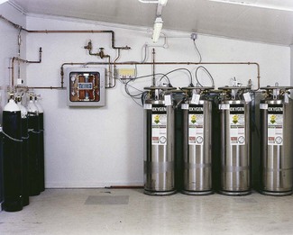
Liquid cylinder (LC) installations
Where the annual consumption of a hospital is considered too great for a compressed cylinder manifold but is insufficient for a CLS, then a liquid cylinder (LC) installation can be considered. This type of installation is not dissimilar to a cylinder manifold, having the same configuration of two cylinder banks and a control panel (Fig. 1.17), but has significant advantages in that each LC contains the equivalent gas capacity of 24 J size compressed gas cylinders. On a typical four-cylinder LC manifold, this is operationally equivalent to 72 size J cylinders (only 75% of the gas capacity is usable as the low liquid level alarm activates when the volume of contents falls to 25%). Another major advantage over compressed cylinders is that the LCs are a semi-permanent installation, and as such are charged from a remote fill point, usually on the outside wall of the compound; this removes the need for manual handling and connecting.
Oxygen concentrators (PSA plant)
Operational process
The major components of a hospital PSA plant are:
Fig. 1.18 shows a schematic layout for a hospital system.
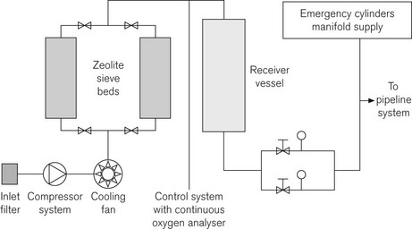
Should the plant fail, the emergency cylinder manifold will feed into the pipeline at higher concentrations (99.5%) than the plant’s operating norm of 95%. This may have an effect on downstream equipment, particularly in critical care areas.
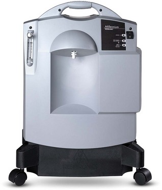
A more appropriate application for oxygen concentrators is in the home environment where a low-flow, low-pressure system can provide continuous domiciliary oxygen to COPD patients. Typical units (Fig. 1.19) operate on a mains supply and can provide up to 51 min−1 at an oxygen concentration of 94%. They are extremely efficient, require little maintenance by the patient apart from periodic cleaning of the inlet filter and can pipe oxygen around the home to small wall-mounted outlets. The concentrator is usually sited in a hallway and needs no special ventilation. The typical noise level when operating normally is around 40 db.
Medical compressed air
2. Cylinders connected to a manifold
3. By mixing liquid oxygen and liquid nitrogen, also known as synthetic medical air (SMA).
This section will deal with the provision of MA by compressors.
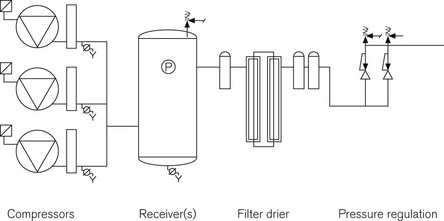
The basic components of MA generation are the same as those found in any industrial compressed air system: a compressor, a receiver for the storage of gas and some form of regulator to monitor and control the pressure in the pipeline (Fig. 1.20). Where MA production differs is in the degree of conditioning applied to the raw compressed air before it is administered to the patient. Compressors for MA plant can be any of three types: reciprocating, Archimedean screw or rotary vane. All have their individual benefits and the ultimate choice of process is based on demand, location and initial cost. Whichever pumps are used they should be identical to each other and capable of meeting total hospital demand with one pump off line.
MA may be contaminated by a number of substances including:
• oil – a lubricating agent used in the compressor that may become an aerosol and be carried into the air stream
• particulate debris – either present in the raw uncompressed air or picked up during compression/storage
• water – a compression process by-product which may collect in the receiver or pipeline.
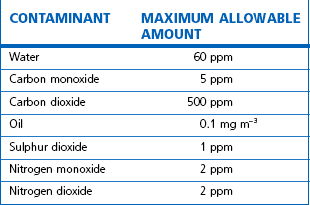
Regulations mandate the removal of these contaminants before MA is administered to patients; this is achieved by a series of filters and driers installed after compression but before distribution into the pipeline system. See Table 1.10 for the specification required for MA by the European Pharmacopoeia.
Synthetic air systems
The 1998 European Pharmaceutical monograph for medical air put greater emphasis on the control of hydrocarbons and moisture in the product and, consequently, an increased need for monitoring the performance of air systems is required. As synthetic medical air (SMA) is produced by mixing liquid oxygen and liquid nitrogen in the gas state, it does not contain either hydrocarbons or moisture and may be considered as an alternative to conventional compressed air supplies, either at the design stage of a new hospital or where purity is an issue. The installation utilizes the existing liquid oxygen supply with an adjoining liquid nitrogen vessel. Both vessels have smaller back-up vessels on the site (Fig. 1.21).
Medical vacuum systems
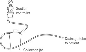
The purpose of MV is to enable the removal of fluids during medical or surgical procedures. The principle of fluid removal is the same in all cases: a drainage tube passes from the patient to an interceptor collection jar where any solid and liquid waste is trapped. The vacuum is then passed through a flow regulator and bacterial filter to the terminal unit in the same way as the medical gasses (Fig. 1.22; see also Chapter 20).
At the vacuum plant (Fig. 1.23), there are additional bacterial traps and collection jars to collect any materials that may have by-passed the patient level filters. Although these components are designed to protect the plant and maintenance staff from contamination, it is advisable to ensure that strict infection control protocols are adhered to during any maintenance work especially if this involves changing the bacterial filters.
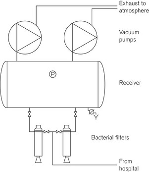
A MV plant can be thought of as a compressor in reverse; air is taken from the MV pipeline and ‘discharged’ into the atmosphere. As with medical air, it is essential to have a degree of redundancy in the system. There should be a minimum of three identical pumps with each pump capable of delivering 100% of the design flow rate. Vacuum pump exhausts may be combined, but where this is the case, a non-return valve must be fitted to the exhaust so that it does not ‘drive’ the standby pump. The exhaust pipeline(s), however, must be vented to atmosphere at high level, normally at roof level and away from all other air intakes or openings into the building (doors, windows, etc.).
Performance levels and specifications for a medical vacuum service
• the design and operating pressure should not be less than 450 mmHg at the plant
• a pressure drop of 50 mmHg within the distribution pipework is permissible
• a minimum pressure of 400 mmHg is required at the back of the terminal unit
• a pressure drop of 100 mmHg is allowed across the terminal unit to the probe, which has to maintain a minimum pressure of at least 300 mmHg whilst delivering a flow rate of 40 1 min−1.
Anaesthetic gas scavenging systems
These are considered specifically in Chapter 18. They do, however, form part of what is termed Medical Gas Piped Services, and common aspects of the piping and distribution are considered further in this chapter.
Alarm and indication systems for piped gasses
The main plant alarm (Table 1.11) consists of a series of panels placed in strategic locations throughout the hospital. These will usually give the indication that everything is normal; their main function though is to give advance warning of a potential system failure. For example, if the duty bank on a manifold runs out, the standby bank will automatically come on-stream. As soon as this happens, the first condition alarm will be triggered indicating that cylinders need changing on that manifold. The service is not in danger, as the manifold is designed to act in this way. If no one attends to the manifold and the standby bank also runs out, the second condition alarm will be activated: at this point the system is about to run out of gas. If the pressure does fall below the minimum required then the final condition – pressure fault – will commence. At this stage, patients will need to be provided with alternative supplies.

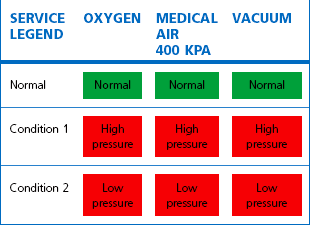
A local or area alarm panel fulfils a very different function. Here the alarm condition is used to indicate that something has already gone wrong. Each gas supplied to a ward or department is monitored for faults by a pressure switch mounted in the pipeline, downstream of the final area valved service unit (AVSU). Typically this is set at ±20% of the line pressure specified for a particular gas such that, if a high- or low-pressure condition occurs within the area, the alarm will indicate the fact (Table 1.12).
Distribution systems
The ‘gasses’ normally distributed by pipeline in hospitals within the UK are:
They all carry an individual colour code, as shown in Figure 1.24.
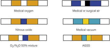
Other gasses, such as helium and hydrogen, are usually only supplied as piped services to pathology laboratories and so are not considered further.
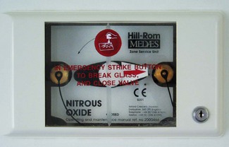
Valves at ward entrances or departmental isolation valves are normally termed AVSUs (Area Valved Service Units) or ZSU (Zone Service Units) and are specifically designed to provide not only gas isolation but also other functions as described below. Essentially, an AVSU comprises a lockable box that has a glass-fronted panel, which can be broken by the ward staff to allow isolation of gas flow to areas in case of fire, pipeline fracture or other emergency (Fig. 1.25).
The pipework itself should be identified by labels placed upon it at regular intervals (Fig. 1.24) in accordance with the identification code described in Section 13 of HTM 02-01 and further marked as to the direction of flow.
Terminal outlets
The distribution pipework terminates in wall- or pendant-mounted self-sealing socket outlets (Fig. 1.26).
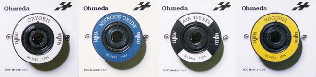
Figure 1.26 Terminal outlets. Note the different diameter recesses (collar indexing system) that match the collar on the relevant probe (see Fig. 1.27).
1. A termination assembly permanently attached to the appropriate pipeline
2. A socket assembly containing the quick connect probe socket, commonly known as a Schrader socket in the UK. This can be removed by a service engineer, but must be designed so that it cannot be accidentally connected to a different gas service.
It is essential that the assembly design ensures gas specificity for each component, such that no terminal unit can be assembled and include parts from different gas termination outlets. The identity of the gas for each terminal unit should be permanently displayed on all individual components. The socket assembly, when assembled will only accept a probe with the same gas identity, by utilizing a collar indexing system that is unique to that gas service.
Flexible pipeline
This connects the terminal outlet to the medical equipment; it has three components:
1. A quick connect (Schrader) probe that fits the terminal outlet
3. A NIST connection that fits the equipment, e.g. the anaesthetic machine.
Quick connect probe
The male part of the probe for the terminal outlet is the same size for all gasses, but in order to prevent connection to the wrong gas service it has a protruding (gas specific) indexing collar (Fig. 1.27). This collar has a unique diameter that only fits the matching recess of the socket assembly for that gas.
The British Standard also stipulates the following:
• It must not be possible to twist the probe while it is connected to the unit (unless it is connected vertically to a pendant). To this end, the collar is provided with a notch that fits over a rigid pin in the socket assembly.
• It must be possible to insert or remove the probe simply and quickly using only one hand. In order to achieve this, the socket assembly has a spring-loaded outer ring, which when depressed releases the locking mechanism holding the probe, and causes the probe to be ejected.
• The unit must seal off the flow of gas when the probe is withdrawn.
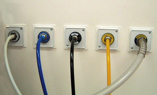
The flexible hosepipe
• to produce complete hose assemblies (with the appropriate connections pre-attached) for the different gas services, under strict quality-control systems and with necessary checks to ensure correct application. Furthermore, it is now recommended practice that a damaged hose should not be repaired on-site but returned in its entirety to the manufacturer in exchange for a factory-made service replacement
• to use characteristically coloured tubing for each gas (Fig. 1.28).
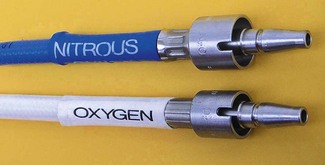
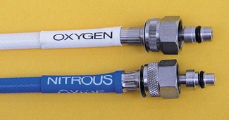
The non-interchangeable screw thread (NIST) connector
To ensure that the gas supply is attached correctly to the relevant piece of medical equipment, each hose is fitted with an unique downstream connector. This takes the form of a probe and nut (Fig. 1.29). The probe has a unique profile for each gas supply and fits only the union on the receiving equipment. This profile consists of two cylindrical shapes which together form a unique combination. For example, in Fig. 1.29 the outer part of the nitrous oxide probe is smaller than that for oxygen, but the inner part is larger. Thus, although the outer tip of the nitrous probe fits into the oxygen receiver, the larger inner part will prevent full engagement. Conversely, the outer part of the oxygen probe is too large to engage with the nitrous oxide receiver.
Tests and checks for medical gas piped services
• Anaesthetists are only responsible for checking that part of the medical gas pipeline services (MGPS) system between the terminal unit and the patient. They should be able to take the quality and unfailing supply of gasses for granted.
• Quality control is usually considered to be the province of the hospital pharmacist, who should order, or make, tests to confirm the identity of the gas, its purity and composition, and freedom from contaminants, including solid particulate matter. Compressed air should also be examined for water vapour and oil mist on a quarterly basis to ensure compliance with the European Pharmacopoeia. The pharmacist is also usually responsible for maintaining adequate supplies of cylinders.
• The engineering department under the direction of the authorized person (AP) is responsible for the day-to-day management and operation of the MGPS and for organizing planned preventive maintenance, emergency repairs, design compliance, continuity of supply and indication/warning systems (alarms).
• Designated theatre staff are usually responsible for changing cylinders on anaesthetic machines and maintaining a store of portable oxygen cylinders with flowmeters and suction equipment for use in emergencies or during shut down for maintenance and alterations.
• The anaesthetist is responsible for the correct insertion of the pipeline probes and any necessary adjustments.
• HTM 02-01 (part B) describes a ‘permit to work’ system. Essentially, this is a code of practice for repairs and preventive maintenance on the MGPS system in which the engineer discusses with the appropriate people the nature and timings of the work to be done and ensures that independent services for medical gasses such as oxygen and vacuum are made available as required. The ‘permit to work’ document has five parts and may at first seem to be yet another proliferation of the already burdensome paperwork in hospitals. It does, however, increase safety and improve the relationships between departments.
• Finally, and most importantly, the whole operation and management of the medical gas system is described in HTM 02-01 part B – Operational Management. This requires that there be a written policy on the use and management of medical gasses with defined responsibilities and roles. It is essential that this document is produced for each hospital, specific to the risks and procedures of that particular site. The medical gas supplier should be in a position to assist in its production.
BOC Gas. Safe with medical gasses. Guildford, Surrey: BOC Ltd; 2002.
British Standards Institute. Part 1 Medical Gas Pipeline Systems – Terminal Units for Compressed Medical Gasses and Vacuum, BS EN 737, Milton Keynes, UK, British Standards Institution, 1998.
British Standards Institute. Anaesthetic and Respiratory Equipment Compatibility with Oxygen, BS EN ISO 15001, Milton Keynes, UK, British Standards Institution, 2004.
British Standards Institute. Part 2 Medical Gas Pipeline Systems – Anaesthetic Gas Scavenging Systems – Basic Requirement Medical Gas Pipeline Systems, BS EN 737, Milton Keynes, UK, British Standards Institution, 1998.
British Standards Institute. Part 3 Medical Gas Pipeline Systems – Pipelines for Compressed Medical Gasses and Vacuum, BS EN 737, Milton Keynes, UK, British Standards Institution, 2000.
British Standards Institute. Part 1 Pressure Regulators for use with Medical Gasses – Pressure Regulators and Pressure Regulators with Flowmetering Devices, BS EN 738, Milton Keynes, UK, British Standards Institution, 1997.
British Standards Institute. Part 2 Pressure Regulators for Use with Medical Gasses – Manifold and Line Pressure Regulators, BS EN 738, Milton Keynes, UK, British Standards Institution, 1999.
British Standards Institute. Part 3 Pressure Regulators for Use with Medical Gasses – Pressure Regulators with Integral Cylinder valves, BS EN 738, Milton Keynes, UK, British Standards Institution, 1999.
British Standards Institute. Specification for Probes (quick connectors) for use with Medical Gas Pipeline Systems, BS 5682, Milton Keynes, UK, British Standards Institution, 1998.
British Standards Institute. Transportable Gas Cylinders.Gas Cylinder Identification (Excluding LPG) Colour Coding, BS EN 1089–1083, Milton Keynes, UK, British Standards Institution, 2004.
HTM 02-01. Medical Gas Pipeline Systems – Design, Installation, Validation and Verification. London: The Stationery Office; 2006.
Grant WJ. Medical gasses – their properties and uses. Aylesbury: HM & M; 2005.
International Organization for Standardization. Small Medical Gas Cylinders, Pin Index Yoke-type Valve Connections, ISO 407, Geneva, International Organization for Standardization, 2004.
International Organization for Standardization. Cylinder Valve Outlets for Gases and Gas Mixtures – Selection and Dimensioning, ISO 5145, Geneva, International Organization for Standardization, 2004.
International Organization for Standardization. Gas Cylinders for Medical Use – Marking for Identification of Content, ISO 32–31, Geneva, International Organization for Standardization, 1977.
International Organization for Standardization. Terminal Units for Medical Gas Pipeline Systems – Part 1: Terminal Units for Use with Compressed Medical Gases and Vacuum, ISO 9170–9171, Geneva, International Organization for Standardization, 2008.
[/level-membership-for-anesthesiology-category][not-level-membership-for-anesthesiology-category]
Chapter 1 The supply of anaesthetic and other medical gasses
Properties of medical gasses
The properties of some of the common medical gasses are summarized in Table 1.1. The newer gasses and their potential therapeutic indications are briefly discussed below.
Table 1.1 Physical properties of common pressurized gasses
N/A, not applicable. * Sublimation.
Note: all values STP. Mixed gasses, e.g. Heliox, will have different physical properties. For exact values, please contact the manufacturer.
Details of carbogen (5% CO2 + 95% O2), lung function gasses, medical gasses for laser surgery and other agents not listed here are available from the manufacturers. Extensive information on the properties of all gasses and data sheets containing up-to-date product information can be obtained from the BOC Medical Gasses website www.bocmedical.com.
Heliox
• It has a lower density than air (0.42 kg/m3 vs 1.22 kg/m3 at 15°C and 1 atm) and hence a lower Reynolds number in any given situation, resulting in a higher likelihood of laminar gas flow characteristics.
• It has a higher thermal conductivity than air, which is of significance when its gas flow measurement is based on this principle (see Chapter 2, Hot wire anemometry).
Medical gas cylinders
Modern cylinders are manufactured using lightweight strong chrome-molybdenum steels which, as well as conforming to stringent material standards, can be filled to pressures of up to 300 bar g (where (g) denotes gauge pressure; see Chapter 2). Cylinders were previously made of the much heavier low-carbon steels: few of these are in circulation any longer in the UK.
Cylinder sizes
Technically, cylinders are defined by their water capacity and range between 1.2 L and 47.2 L, and are identified by a size code ranging from C to J (Fig. 1.1). This notation incorporates a pressure aspect to give an indication of available gas volume. Tables 1.2–1.7 give details for oxygen, nitrous oxide, Entonox, carbon dioxide, Heliox21, xenon, nitric oxide and carbon monoxide cylinders.
Figure 1.1 Cylinder types and sizes, valves types and pin index valves.
(from BOC Medical, with permission).
Table 1.4 Relative sizes and specifications of commonly used Entonox cylinders
Entonox, a mixture of 50% oxygen and 50% nitrous oxide, exists as a gas. The pseudo critical temperature of Entonox in pipelines at 4.1 bar is below −30°C. Nitrous oxide in an Entonox cylinder, however, begins to separate out from Entonox if the temperature falls below −6°C. A homogenous mixture is again obtained when the temperature is raised above 10°C and the cylinder is agitated.
Table 1.6 Relative sizes and specifications of commonly used Heliox21 cylinders
| CYLINDER SIZE | HL | HX |
|---|---|---|
| Contents (L) | 8200 | 1780 |
| Nominal cylinder pressure at 15°C (bar) | 200 | 200 |
| Valve type | Side outlet | Integral |
| Dimensions (mm) | 1540 × 230 | 940 × 140 |
| Empty weight (kg) | 50 | 15.5 |
Cylinder filling and maintenance
Most gasses such as oxygen, medical air, helium and Heliox21 are stored in cylinders in a compressed gaseous state and are normally filled by pressure. Nitrous oxide and carbon dioxide, however, are liquefied gasses under pressure. The liquid is in equilibrium with the gas, the pressure being dependent on the temperature. These gasses are charged by weight and not by pressure. The maximum weight of gas filled into the cylinder divided by the weight of water that would completely fill the cylinder is called the maximum filling ratio and is governed by legislation. This ‘fill ratio’, termed ‘fill density’ elsewhere, is critical. In the UK this value is 0.75 at 15.5°C for nitrous oxide and carbon dioxide. Note that due to the difference in the densities of liquefied gasses and water this ratio is not the same as the proportion of the volume of the cylinder filled by the liquid phase, which is nearer 90 to 95% for nitrous oxide. If there is insufficient gas space left in the cylinder after filling, a comparatively small increase in temperature will cause a significant increase in pressure and could, in extreme circumstances, cause the cylinder to rupture.
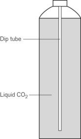
Some applications require carbon dioxide in liquid form. This is supplied using cylinders fitted with a ‘dip tube’ connected to the cylinder valve, which allows liquid from the bottom of the cylinder to be drawn up through the valve (Fig. 1.2). These cylinders, supplied in F size and known as LF, have a white stripe down the length of the cylinder body. For other CO2 applications where vapour is required, VF cylinders should be used. It is important to ensure that the correct cylinder is used to prevent damage to equipment.
Cylinder identification
The correct method of identifying the contents of a cylinder is to read the collar identification label (rather than assuming that the colour of the cylinder or the type of valve fitted reliably indicates gas inside it). The label (Fig. 1.3) is a legal requirement and contains all the key information for the user:
• product name, chemical symbol and pharmaceutical form of the product
• directions for use and information for storage and handling.
The cylinder label also has a unique batch label (Fig. 1.4), which contains: the batch number; fill and expiry date; and the size and type of gas. The label is changed every time the cylinder is filled and serves two important functions: (a) it provides vital information for a batch recall should the cylinder be involved in an incident; and (b) it provides information for proper cylinder rotation.
Cylinder testing
All cylinders must undergo hydraulic testing and internal inspection at regular intervals, to ensure they remain safe to use. The test is carried out every 10 years for steel cylinders and every 5 years for composite cylinders. A colour-coded plastic ring between the valve and the cylinder neck indicates when the next test date is due. In general, cylinders have a long service life and tend to be withdrawn for reasons of technical obsolescence rather than deterioration per se.
Colour coding
Medical cylinders in the UK conform to colour codes specified in ISO 32:1972 and EN 1089-3. The colour coding relates only to the shoulder of the cylinder. Figure 1.5 shows the colour codes for medical gas cylinders in the UK.
Cylinder valves
Medical cylinder valves can generally be categorized as follows:
• Non-integral valves (which require manual attachment of an external pressure regulator):
• Integral valves (which have a built in regulator and possibly flowmeter).
Pin index system
Small pin index valves (Fig. 1.6) are fitted to small cylinders (less than 5 litre capacity) which are commonly connected directly to medical equipment such as anaesthetic machines. Newer designs using a thumbwheel do away with the need for a spanner to operate the valve.
Side spindle pin index valves (Fig. 1.6) These are fitted to large cylinders of medical oxygen, medical air, Entonox used in pipeline manifolds and F size Entonox cylinders.
Both types of pin index valves conform to BS EN ISO 407:2004 and adopt an indexed outlet system which incorporates a gas-specific combination of holes positioned to correspond to pins located on the receiving equipment, making it impossible to connect the cylinder to an incorrect gas connection. Fig. 1.1 shows the different pin positions. The pin index system also prevents charging with the wrong gas, as the gas suppliers use the same non-interconnectable system for their filling connections.
Pin index cylinders require a washer (seal) between the face of the cylinder valve outlet and the equipment to which it is fitted. This bonded non-combustible seal, known as a ‘Bodok’ washer (Figs 1.7 and 1.8), must be kept clean and should never become contaminated with oil or grease. If a gas tight seal cannot be achieved by moderate tightening of the screw clamp, it is recommended that the seal be renewed. Excessive force should never be used.
Bull nose outlet valve
This type of valve (Fig. 1.9) is fitted to F and G size cylinders including medical oxygen, medical air, helium, and mixed gasses such as carbogen and Heliox. The valve is spindle key operated and has a 5/8-inch female outlet thread into which a regulator is fitted. The spindle mechanism is assembled in two parts. This permits a gas tight seal to be achieved without the use of excessive force and increases its operational life.
All bull nose valves are fitted with an RP (residual pressure) device, to ensure that a positive pressure of approximately 3 bar is retained in the cylinder (Fig. 1.10). This prevents the ingress of moisture should the valve be left open when the cylinder is empty. When connecting regulator equipment to the valve, the user should always adopt the proper connecting procedure:
Figure 1.10 Schematic showing ‘residual pressure’ device of a bull nose cylinder valve.
Redrawn using material kindly provided by Müller Gas Equipment A/S, Denmark.
• Ensure the ‘O’ ring (Fig. 1.11) fitted to the regulator is in good condition and hand tighten the regulator only.
• Once fitted, open the spindle valve slowly (to prevent a gas surge) at least one full turn and note the position of the regulator gauge needle.
• A simple test for leaks can be carried out by closing the cylinder spindle valve and noting any drop in pressure shown on the gauge. If a leak does exist, spraying the joints with a leak detection spray will identify it. If a leak is evident at the valve outlet, replace the ‘O’ ring and repeat the procedure. If the leak persists, fit a replacement regulator. (Note: It is vitally important that any leak detection spray has been approved by the cylinder supplier as being compatible with their equipment and the gas.)
• When changing an empty cylinder, close the cylinder valve and vent the regulator completely before attempting to disconnect it.
Handwheel valves
Large nitrous oxide cylinders for use on cylinder manifolds and carbon dioxide cylinders of size F and G are fitted with handwheel valves which are surrounded by a protective guard (Fig. 1.12), and have a gas specific, male thread, side outlet.
Integral valves
The introduction of integral valves (Fig. 1.13), which have their own built-in regulator, has revolutionized the industry by greatly improving safety and eliminating the need for regulator maintenance by hospitals. They have a number of advantages:
• The regulator assembly is manufactured in a clean environment and is much less prone to particulate contamination.
• The built-in regulator eliminates the risk of incorrect regulator attachment which could result in damage to lower-pressure rated equipment.
• The valves are surrounded by guards which reduce the risk of damage and ease manual handling of the cylinder.
• They are considerably easier to use and have live pressure gauges built in for checking cylinder contents.
• The valves possess two outlets – a variable flow outlet (via a fir tree connector) and a fixed pressure outlet to connect equipment requiring a static driving pressure.
A commonly encountered version of the integral valve has a combination of a clickstop flowmeter giving 0–15 l min−1 in stepped increments and a female BS Schraeder connection at 4 bar g to provide high pressure gas. This type of valve is currently fitted to cylinders of up to 10 l water capacity. Care must be taken to ensure that the flowmeter selector dial is not ‘parked’ between click stops as this will result in a cessation of gas flow.
Storage of medical gas cylinders
• be under cover (preferably inside) and not subjected to extremes of heat
• be kept dry, clean and well ventilated
• have good access for deliveries and a reasonably level floor surface
• allow segregation of ‘full’ and ‘empty’ cylinders
[/not-level-membership-for-anesthesiology-category]
