Chapter 21 The Electrophysiological Laboratory
Technologic Advances and Future Development
Newly Designed or “Retrofit”?
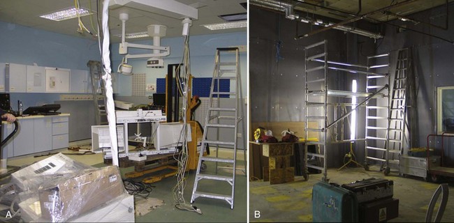
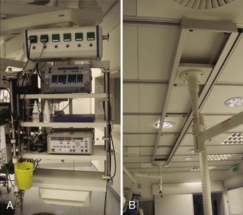
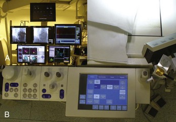
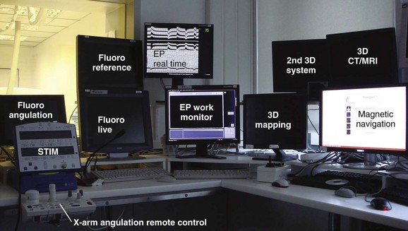
Many considerations need to be taken into account when deciding to either design a state-of-the-art cath lab in a newly constructed area or renovating an older lab with up-to-date technologies (Figure 21-1). One of the biggest problems is having enough space to fit not only all the equipment necessary for the procedure (Figure 21-2) but also equipment needed only in an emergency. In addition, ample space for moving the patient into and out of the room via stretcher or patient bed and sufficient in-room storage are essential. Normal items such as telephone lines, a data point for the hospital information system (HIS), sufficient lighting, and easy access from the sink to the sterile field are involved as well. The placement of gases and suction outlets in the procedure room should also be given attention.
Minimal Standards for Invasive Electrophysiology (“The Must Have”)
To visualize catheter positioning, a fluoroscopic imaging system with at least a single C-arm is necessary. The system should be programmable to a certain extent to control radiation exposure (Figure 21-3).1 Because comparably less radiation exposure is needed to image the metal electrodes of a catheter compared with the resolution required for lesion assessment in coronary artery interventions, a special setting should be reserved for EP procedures. The C-arm should be rotatable by at least 90 degrees in both the right anterior oblique and the left anterior oblique positions, and cranial or caudal angulations are not often necessary. To reduce radiation exposure to the operator, proper Plexiglas lead protection, both “under the table” (closest position to the x-ray beam) and “over the table” against scattered radiation from the patient is a legal requirement. In addition, the image should, whenever possible, be centered on the chamber of interest and the table should be locked in the optimal position for all angulations to avoid unnecessary radiation exposure. Finally, collimation and “fencing in” of the lung fields should be routine, and any unnecessary metallic devices should be removed from the area to be imaged because they result in an automatic intensification of radiation exposure (e.g., transesophageal echocardiography probes should be removed from view). European laws require the documentation of both total exposure time and dosage of the overall deployed radiation. In regard to applied fluoroscopy, the ALARA (as low as reasonably achievable) principle should be followed, and unnecessary imaging should be avoided.1 If available, the “last image hold” option should be used.2
Electrophysiology Recording System (Including Intracardiac Pressure Recordings)
The minimal requirements for EP recording systems are fairly subjective. Although some operators work with only 32 channels, at least 64 channels seems to be the current standard. In addition to the standard display of the 12-lead electrocardiogram (ECG), bipolar and unipolar signals should be programmable.3 The gain applied to any given recording should be individually adjustable, and electrodes belonging to one catheter are usually grouped (e.g., by color). Although the order of the displayed signals is a question of personal preference and training, the signal accuracy is of utmost importance. Too large a noise level is unacceptable because it could mislead the operator during the mapping process. Signal quality during energy application also is important, and every effort should be made to achieve clean signals to allow drag lesions rather than sequential point-by-point applications. In addition to the electrical signals, the recording of at least one invasive pressure should be possible (e.g., for emergency percutaneous transluminal coronary angioplasty or hemodynamic monitoring).
Equipment for Advanced Electrophysiology Labs
Although most simple EP substrates can be readily treated by using conventional two-dimensional fluoroscopy in conjunction with intracardiac signals, catheter ablation of complex arrhythmias such as ventricular tachycardia, incisional atrial tachycardia, or atrial fibrillation are facilitated by three-dimensional mapping systems. Following the cardiac activation across a complex three-dimensional geometry of a given cardiac chamber can be extremely helpful in performing confirmative diagnostic pacing maneuvers (e.g., entrainment in the critical isthmus of a re-entry). Because the ablation catheter usually is depicted in a real-time fashion, roaming inside the chamber of interest, three-dimensional movements are possible without controlling the movement with fluoroscopy. Although three-dimensional mapping systems should reduce overall fluoroscopy exposure, some investigators did not observe any change in their practice, whereas others relying completely on the real-time depiction of the mapping catheter demonstrated significant reductions after a learning curve.4–6 For reduction of radiation exposure, however, the accuracy with which the catheter position is displayed is key. Two different systems have established themselves as routinely used three-dimensional tools in most cath labs performing advanced EP procedures.
NAVx and EnSite
The concept of the original LocaLisa system (now implemented in the NAVx system; St Jude Medical, St Paul, MN) is based on real-time display of all intracardiac electrodes using surface patches in all three spatial directions, which act like condensators.7 By emitting a small current between opposite patches, any interposed catheter changes the received current and thereby becomes locatable. After reconstruction of the geometry, sequentially acquired activation information can be superimposed on the three-dimensional shell to delineate the arrhythmia substrate.
The EnSite balloon (St Jude Medical) works on the same platform by using essentially the same patches and concepts.8 In addition to the sequentially acquired three-dimensional geometry, simultaneously acquired unipolar electrical information can be projected from the multi-electrode array using an inverse solution to the Laplace equation. This system has been reported to be of additional benefit, especially in transient and nontolerant arrhythmias.
Electroanatomic Magnetic System: CARTO
The CARTO system (Biosense Webster, Inc., Diamond Bar, CA) acts on a concept similar to that of a global positioning system, in which a small sensor on the tip of the ablation catheter is located in three different ultra-low-energy magnetic fields encoding the chest of the patient via electromagnets positioned below the patient table (so-called location pad).9 Through visual display of sequentially acquired sites (and their corresponding electrical information, e.g., voltage amplitude or activation time), a color-coded map is created. Because the mapping electrode is displayed in real time, nonfluoroscopic mapping ideally is enabled, but in clinical practice some fluoroscopy is still required.
Image Integration
Currently, all three-dimensional mapping systems are able to integrate previously acquired three-dimensional DICOM-standard (Digital Imaging and Communications in Medicine) information derived from either computed tomography or cardiac magnetic resonance imaging scans.10–11 However, accurate merging requires careful registration (e.g., to contrast injection or distinct anatomic landmarks) to obtain optimal results without the operator being misled. Knowing the targeted chamber ahead of time may lower overall radiation exposure and allows specific planning of the procedure (e.g., larger catheter curves in cases of enlarged cardiac chambers). The display of the acquired three-dimensional map on top of the fluoroscopy reference pictures allows even better orientation during the case.
Alternative Ablation Energy Sources
As an alternative to the commonly used RF current, other ablation sources such as cryothermia techniques have been introduced in recent years.12 Besides balloon devices for pulmonary vein isolation, some operators choose cryothermia for anteroseptal accessory pathways to use the transient freezing option (approximately –10° C), so-called cryo-mapping, in selected cases.13
Further alternative energy sources are laser energy, microwave, and ultrasound energy, modalities mostly reserved for study protocols at this time.14
Advanced Technologies in the Electrophysiology Lab
Remote Navigation
Remote navigation is the umbrella term for two recently introduced technologies. By using computerized workstations from within the control room, investigators are no longer exposed to scattered radiation (Figure 21-4).
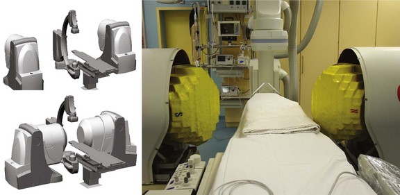
Two remote catheter navigation systems have been introduced into clinical practice, both enabling remote control of the ablation catheter.1–3 One is based on an electromechanical concept in which two steerable sheaths guide a conventional catheter; the other is based on a steerable, permanent magnetic field in which a magnetically equipped catheter must be aligned in a parallel position (Figure 21-5).
The electromechanical robotic system (Sensei; Hansen Medical, Mountain View, CA) consists of a “master” input that transmits the operator’s movement with a joystick via an electromechanical “slave” at the patient’s side (Artisan; Hansen Medical).15 This remote catheter manipulator controls the tip of two guiding sheaths (14 and 11.5 Fr) that fit any conventional standard ablation catheter. The guiding sheaths (inner lumen of 8.5 Fr) work on mechanical pull-wire mechanisms that steer the catheter in a fashion similar to that of conventional guiding catheters.
Magnetic Navigation
Magnetic navigation works on the concept of small magnets, integrated in the tip of a soft ablation catheter that can be moved with a well-defined outer magnetic field (0.08 T). By changing the orientation of the outer magnets, the catheter tip will align parallel to this outer magnetic field direction. The combination with a mechanical motor drive allows operating the magnetic mapping and ablation catheter in a fully remote-controlled fashion.16 The specialized, magnetically enabled ablation catheter was initially equipped with a solid 4-mm tip ablation electrode; an irrigated tip version has recently been introduced.
Other Image Integration Technologies
Intracardiac ultrasound catheters have recently been introduced in an attempt to integrate three-dimensional echocardiographic information to reduce mapping time further, thus facilitating trans-septal punctures and eventually directly depicting the lesion formation during energy delivery.17 Although these systems are quite popular in the United States, the European experience has been significantly sparse.
To overcome the possible problem of pre-procedural three-dimensional imaging in different cardiac rhythms, volume load, and patient positioning, rotational angiography has been successfully implemented in the EP labs. While a timed contrast injection is performed, the C-arm rotates around the patient and acquires computed tomographic–like images that can be computed to three-dimensional DICOM formats.18 These three-dimensional datasets can be transferred to the three-dimensional mapping systems as well as to a “ghost” picture-in-picture display on the live fluoroscopy screen (e.g., iPilot, Siemens Medical Solutions, Munich, Germany).
Al-Ahmad A, Grossman JD, Wang PJ. Early experience with a computerized robotically controlled catheter system. J Interv Card Electrophysiol. 2005;12(3):199-202.
Ben-Haim SA, Osadchy D, Schuster I, et al. Nonfluoroscopic, in vivo navigation and mapping technology. Nat Med. 1996;2(12):1393-1395.
Chun KR, Schmidt B, Metzner A, et al. The “single big cryoballoon” technique for acute pulmonary vein isolation in patients with paroxysmal atrial fibrillation: A prospective observational single centre study. Eur Heart J. 2009;30(6):699-709.
Ector J, De Buck S, Adams J, et al. Cardiac three-dimensional magnetic resonance imaging and fluoroscopy merging: A new approach for electroanatomic mapping to assist catheter ablation. Circulation. 2005;112(24):3769-3776.
Ernst S, Ouyang F, Linder C, et al. Initial experience with remote catheter ablation using a novel magnetic navigation system: Magnetic remote catheter ablation. Circulation. 2004;109(12):1472-1475.
Hirshfeld JWJr, Balter S, Brinker JA, et al. ACCF/AHA/HRS/SCAI clinical competence statement on physician knowledge to optimize patient safety and image quality in fluoroscopically guided invasive cardiovascular procedures: A report of the American College of Cardiology Foundation/American Heart Association/American College of Physicians Task Force on Clinical Competence and Training. Circulation. 2005;111(4):511-532.
Limacher MC, Douglas PS, Germano G, et al. ACC expert consensus document. Radiation safety in the practice of cardiology. American College of Cardiology. J Am Coll Cardiol. 1998;31(4):892-913.
Marrouche NF, Guenther J, Segerson NM, et al. Randomized comparison between open irrigation technology and intracardiac-echo-guided energy delivery for pulmonary vein antrum isolation: Procedural parameters, outcomes, and the effect on esophageal injury. J Cardiovasc Electrophysiol. 2007;18(6):583-588.
Orlov MV, Hoffmeister P, Chaudhry GM, et al. Three-dimensional rotational angiography of the left atrium and esophagus—a virtual computed tomography scan in the electrophysiology lab? Heart Rhythm. 2007;4(1):37-43.
Reddy VY, Malchano ZJ, Holmvang G, et al. Integration of cardiac magnetic resonance imaging with three-dimensional electroanatomic mapping to guide left ventricular catheter manipulation: Feasibility in a porcine model of healed myocardial infarction. J Am Coll Cardiol. 2004;44(11):2202-2213.
Reddy VY, Neuzil P, d’Avila A, et al. Balloon catheter ablation to treat paroxysmal atrial fibrillation: What is the level of pulmonary venous isolation? Heart Rhythm. 2008;5(3):353-360.
Scheinman M, Calkins H, Gillette P, et al. NASPE policy statement on catheter ablation: Personnel, policy, procedures, and therapeutic recommendations. Pacing Clin Electrophysiol. 2003;26(3):789-799.
Schmitt H, Weber S, Schwab JO, et al. Diagnosis and ablation of focal right atrial tachycardia using a new high-resolution, non-contact mapping system. Am J Cardiol. 2001;87(8):1017-1021. A1015
Wittkampf FH, Wever EF, Derksen R, et al. LocaLisa: New technique for real-time 3-dimensional localization of regular intracardiac electrodes. Circulation. 1999;99(10):1312-1317.
Zrenner B, Dong J, Schreieck J, et al. Transvenous cryoablation versus radiofrequency ablation of the slow pathway for the treatment of atrioventricular nodal re-entrant tachycardia: A prospective randomized pilot study. Eur Heart J. 2004;25(24):2226-2231.
1 Limacher MC, Douglas PS, Germano G, et al. ACC expert consensus document. Radiation safety in the practice of cardiology. American College of Cardiology. J Am Coll Cardiol. 1998;31(4):892-913.
2 Hirshfeld JWJr, Balter S, Brinker JA, et al. ACCF/AHA/HRS/SCAI clinical competence statement on physician knowledge to optimize patient safety and image quality in fluoroscopically guided invasive cardiovascular procedures: A report of the American College of Cardiology Foundation/American Heart Association/American College of Physicians Task Force on Clinical Competence and Training. Circulation. 2005;111(4):511-532.
3 Scheinman M, Calkins H, Gillette P, et al. NASPE policy statement on catheter ablation: Personnel, policy, procedures, and therapeutic recommendations. Pacing Clin Electrophysiol. 2003;26(3):789-799.
4 Stabile G, Scaglione M, Del Greco M, et al. Reduced fluoroscopy exposure during ablation of atrial fibrillation using a novel electroanatomical navigation system: A multicentre experience. Europace. 2011. Epub ahead of print Sep 16
5 Casella M, Pelargonio G, Dello Russo A, et al. “Near-zero” fluoroscopic exposure in supraventricular arrhythmia ablation using the EnSite NavX mapping system: Personal experience and review of the literature. J Interv Cardiovasc Electrophysiol. 2011;31(2):109-118.
6 Verbeet T, Castro J, Morissens M, et al. Use of a new nonfluoroscopic three-dimensional mapping system in type I atrial flutter ablation. Pacing Clin Electrophysiol. 2005;28(suppl 1):S99-S101.
7 Wittkampf FH, Wever EF, Derksen R, et al. LocaLisa: New technique for real-time 3-dimensional localization of regular intracardiac electrodes. Circulation. 1999;99(10):1312-1317.
8 Schmitt H, Weber S, Schwab JO, et al. Diagnosis and ablation of focal right atrial tachycardia using a new high-resolution, non-contact mapping system. Am J Cardiol. 2001;87(8):1017-1021. A1015
9 Ben-Haim SA, Osadchy D, Schuster I, et al. Nonfluoroscopic, in vivo navigation and mapping technology. Nat Med. 1996;2(12):1393-1395.
10 Reddy VY, Malchano ZJ, Holmvang G, et al. Integration of cardiac magnetic resonance imaging with three-dimensional electroanatomic mapping to guide left ventricular catheter manipulation: Feasibility in a porcine model of healed myocardial infarction. J Am Coll Cardiol. 2004;44(11):2202-2213.
11 Ector J, De Buck S, Adams J, et al. Cardiac three-dimensional magnetic resonance imaging and fluoroscopy merging: A new approach for electroanatomic mapping to assist catheter ablation. Circulation. 2005;112(24):3769-3776.
12 Zrenner B, Dong J, Schreieck J, et al. Transvenous cryoablation versus radiofrequency ablation of the slow pathway for the treatment of atrioventricular nodal re-entrant tachycardia: A prospective randomized pilot study. Eur Heart J. 2004;25(24):2226-2231.
13 Chun KR, Schmidt B, Metzner A, et al. The “single big cryoballoon” technique for acute pulmonary vein isolation in patients with paroxysmal atrial fibrillation: A prospective observational single centre study. Eur Heart J. 2009;30(6):699-709.
14 Reddy VY, Neuzil P, d’Avila A, et al. Balloon catheter ablation to treat paroxysmal atrial fibrillation: What is the level of pulmonary venous isolation? Heart Rhythm. 2008;5(3):353-360.
15 Al-Ahmad A, Grossman JD, Wang PJ. Early experience with a computerized robotically controlled catheter system. J Interv Card Electrophysiol. 2005;12(3):199-202.
16 Ernst S, Ouyang F, Linder C, et al. Initial experience with remote catheter ablation using a novel magnetic navigation system: Magnetic remote catheter ablation. Circulation. 2004;109(12):1472-1475.
17 Marrouche NF, Guenther J, Segerson NM, et al. Randomized comparison between open irrigation technology and intracardiac-echo-guided energy delivery for pulmonary vein antrum isolation: Procedural parameters, outcomes, and the effect on esophageal injury. J Cardiovasc Electrophysiol. 2007;18(6):583-588.
18 Orlov MV, Hoffmeister P, Chaudhry GM, et al. Three-dimensional rotational angiography of the left atrium and esophagus—a virtual computed tomography scan in the electrophysiology lab? Heart Rhythm. 2007;4(1):37-43.