The anaesthetic machine
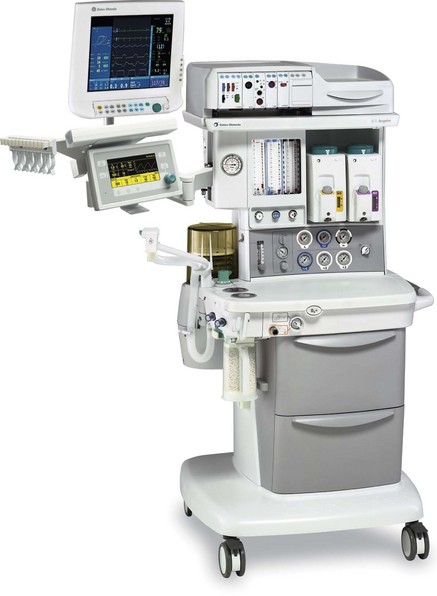
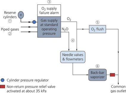
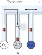
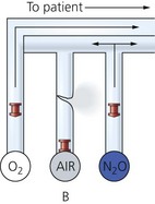
The anaesthetic machine receives medical gases (oxygen, nitrous oxide, air) under pressure and accurately controls the flow of each gas individually. A gas mixture of the desired composition at a defined flow rate is created before a known concentration of an inhalational agent vapour is added. Gas and vapour mixtures are continuously delivered to the common gas outlet of the machine, as fresh gas flow (FGF), and to the breathing sytem and patient (Figs 2.1 and 2.2). It consists of:
1. gas supplies (see Chapter 1)
3. pressure regulators (reducing valves)
7. a variety of other features, e.g. high-flow oxygen flush, pressure relief valve and oxygen supply failure alarm and suction apparatus
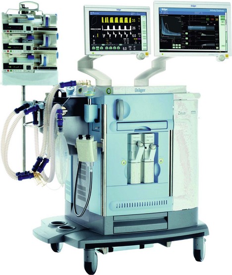
8. most modern anaesthetic machines or stations incorporate a circle breathing system (see Chapter 4) and a bag-in-bottle type ventilator (see Chapter 8).
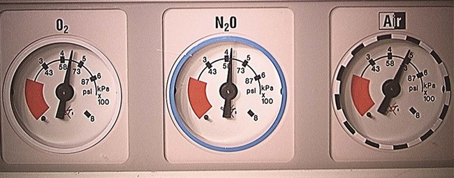
Pressure gauge
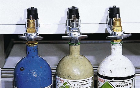
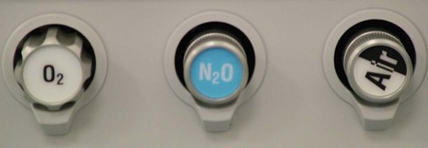
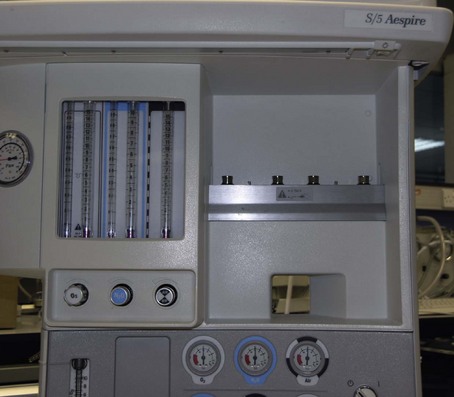
This measures the pressure in the cylinder or pipeline. The pressure gauges for oxygen, nitrous oxide and medical air are mounted in a front-facing panel on the anaesthetic machine (Fig. 2.3).
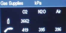
Some modern anaesthetic machine designs have a digital display of the gas supply pressures (Fig. 2.4).
Components
1. A robust, flexible and coiled tube which is oval in cross-section (Fig. 2.5). It should be able to withstand the sudden high pressure when the cylinder is switched on.
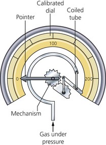
Fig. 2.5 The Bourdon pressure gauge.
2. The tube is sealed at its inner end and connected to a needle pointer which moves over a dial.
Problems in practice and safety features
1. Each pressure gauge is colour-coded and calibrated for a particular gas or vapour. The pressure measured indicates the contents available in an oxygen cylinder. Oxygen is stored as a gas and obeys Boyle’s gas law (pressure × volume = constant). This is not the case in a nitrous oxide cylinder since it is stored as a liquid and vapour.
2. A pressure gauge designed for pipelines should not be used to measure cylinder pressure and vice versa. This leads to inaccuracies and/or damage to the pressure gauge.
3. Should the coiled tube rupture, the gas vents from the back of the pressure gauge casing. The face of the pressure gauge is made of heavy glass as an additional safety feature.
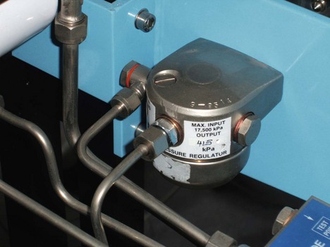
Pressure regulator (reducing valve)
Pressure regulators are used because:
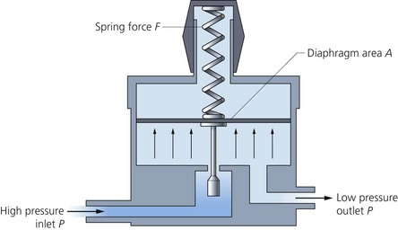
• Gas and vapour are stored under high pressure in cylinders. A regulator reduces the variable cylinder pressure to a constant safer operating pressure of about 400 kPa (just below the pipeline pressure) (Fig. 2.6).
• The temperature and pressure of the cylinder contents decrease with use. In order to maintain flow, constant adjustment is required in the absence of regulators.
• Regulators protect the components of the anaesthetic machine against pressure surges.
• The use of pressure regulators allows low-pressure piping and connectors to be used in the machine. This makes the consequences of any gas leak much less serious.
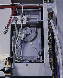
They are positioned between the cylinders and the rest of the anaesthetic machine (Figs 2.7 and 2.8).
Mechanism of action
1. Gas enters the high-pressure chamber and passes into the low-pressure chamber via the valve.
2. The force exerted by the high-pressure gas tries to close the valve. The opposing force of the diaphragm and spring tries to open the valve. A balance is reached between the two opposing forces. This maintains a gas flow under a constant pressure of about 400 kPa.
Problems in practice and safety features
1. Formation of ice inside the regulator can occur. If the cylinder contains water vapour, this may condense and freeze as a result of the heat lost when gas expands on entry into the low-pressure chamber.
3. Relief valves (usually set at 700 kPa) are fitted downstream of the regulators and allow the escape of gas should the regulators fail.
4. A one-way valve is positioned within the cylinder supply line. This prevents backflow and loss of gas from the pipeline supplies should a cylinder not be connected. This one-way valve may be incorporated into the design of the pressure regulator.
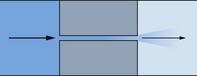
Second-stage regulators and flow restrictors
The control of pipeline pressure surges can be achieved either by using a second-stage pressure regulator or a flow restrictor (Fig. 2.9) – a constriction, between the pipeline supply and the rest of the anaesthetic machine. A lower pressure (100–200 kPa) is achieved. If there are only flow restrictors and no regulators in the pipeline supply, adjustment of the flowmeter controls is usually necessary whenever there is change in pipeline pressure.
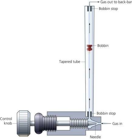
Flow control (needle) valves
These valves control the flow through the flowmeters by manual adjustment. They are positioned at the base of the associated flowmeter tube (Fig. 2.10). Increasing the flow of a gas is achieved by turning the valve in an anticlockwise direction.
Components
1. The body, made of brass, screws into the base of the flowmeter.
2. The stem screws into the body and ends in a needle. It has screw threads allowing fine adjustment.
3. The flow control knobs are labelled and colour-coded.
4. A flow control knob guard is fitted in some designs to protect against accidental adjustment in the flowmeters.
Flowmeters
Flowmeters measure the flow rate of a gas passing through them. They are individually calibrated for each gas. Calibration occurs at room temperature and atmospheric pressure (sea level). They have an accuracy of about ±2.5%. For flows above 1 L/min, the units are L/min, and for flows below that, the units are 100 mL/min (Fig. 2.11).
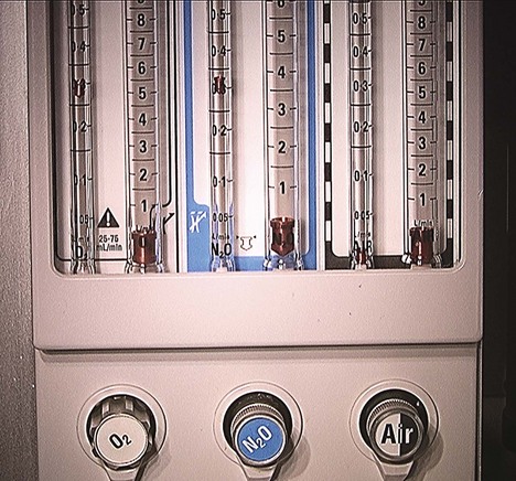
Fig. 2.11 A flowmeter panel.
Mechanism of action
1. When the needle valve is opened, gas is free to enter the tapered tube.
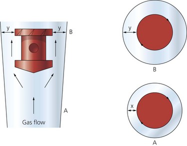
2. The bobbin is held floating within the tube by the gas flow passing around it. The higher the flow rate, the higher the bobbin rises within the tube.
3. The effect of gravity on the bobbin is counteracted by the gas flow. A constant pressure difference across the bobbin exists as it floats.
4. The clearance between the bobbin and the tube wall widens as the gas flow increases (Fig. 2.12).
5. At low flow rates, the clearance is longer and narrower, thus acting as a tube. Under these circumstances, the flow is laminar and a function of gas viscosity (Poiseuille’s law).
6. At high flow rates, the clearance is shorter and wider, thus acting as an orifice. Here, the flow is turbulent and a function of gas density.
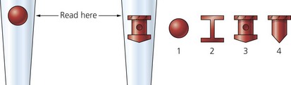
7. The top of the bobbin has slits (flutes) cut into its side. As gas flows past it, the slits cause the bobbin to rotate. A dot on the bobbin indicates to the operator that the bobbin is rotating and not stuck.
8. The reading of the flowmeter is taken from the top of the bobbin (Fig. 2.13). When a ball is used, the reading is generally taken from the midpoint of the ball.
9. When very low flows are required, e.g. in the circle breathing system, an arrangement of two flowmeters in series is used. One flowmeter reads a maximum of 1 L/min allowing fine adjustment of the flow. One flow control per gas is needed for both flowmeters (Fig. 2.14).
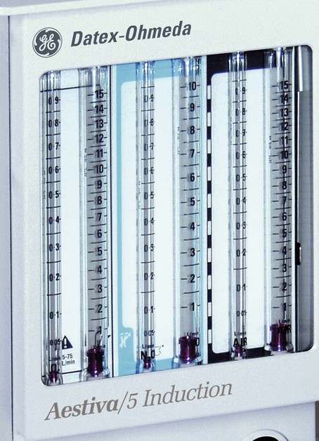
Fig. 2.14 Two flowmeters in series.
10. There is a stop on the oxygen flow control valve to ensure a minimum oxygen flow of 200–300 mL/min past the needle valve. This ensures that the oxygen flow cannot be discontinued completely.
Problems in practice and safety features
1. The flow control knobs are colour-coded for their respective gases. The oxygen control knob is situated to the left (in the UK) and, in some designs, is larger with larger ridges and has a longer stem than the other control knobs, making it easily recognizable (Fig. 2.15). In the USA and Canada, the oxygen control knob is situated to the right.
2. The European Standard for anaesthetic machines (EN 740) requires them to have the means to prevent the delivery of a gas mixture with an oxygen concentration below 25%. Current designs make it impossible for nitrous oxide to be delivered without the addition of a fixed percentage of oxygen. This is achieved by using interactive oxygen and nitrous oxide controls. This helps to prevent the possibility of delivering a hypoxic mixture to the patient. In the mechanical system, two gears are connected together by a precision stainless steel link chain. One gear with 14 teeth is fixed on the nitrous oxide flow control valve spindle. The other gear has 29 teeth and can rotate the oxygen flow control valve spindle, rather like a nut rotating on a bolt. For every 2.07 revolutions of the nitrous oxide flow control knob, the oxygen knob and spindle set to the lowest oxygen flow will rotate once. Because the gear on the oxygen flow control is mounted like a nut on a bolt, oxygen flow can be adjusted independently of nitrous oxide flow.
3. A crack in a flowmeter may result in a hypoxic mixture (Fig. 2.16). To avoid this, oxygen is the last gas to be added to the mixture delivered to the back bar.
4. Flow measurements can become inaccurate if the bobbin sticks to the inside wall of the flowmeter. The commonest causes are:
a) dirt: this is a problem at low flow rates when the clearance is narrow. The source of the dirt is usually a contaminated gas supply. Filters, acting before gas enters the flowmeters, will remove the dirt
b) static electricity: the charge usually builds up over a period of time, leading to inaccuracies of up to 35%. Using antistatic materials in flowmeter construction helps to eliminate any build-up of charge. Application of antistatic spray removes any charge present.
5. Flowmeters are designed to be read in a vertical position, so any change in the position of the machine can affect the accuracy.
6. Pressure rises at the common gas outlet are transmitted back to the gas above the bobbin. This results in a drop in the level of the bobbin with an inaccurate reading. This can happen with minute volume divider ventilators as back pressure is exerted as they cycle with inaccuracies of up to 10%. A flow restrictor is fitted downstream of the flowmeters to prevent this occurring.
7. Accidents have resulted from failure to see the bobbin clearly at the extreme ends of the tube. This can be prevented by illuminating the flowmeter bank and installing a wire stop at the top to prevent the bobbin reaching the top of the tube.
8. If facilities for the use of carbon dioxide are fitted to the machine, the flowmeter is designed to allow a maximum of 500 mL/min to be added to the FGF. This ensures that dangerous levels of hypercarbia are avoided.
9. Highly accurate computer controlled gas mixers are available.
Vaporizers
Vaporizers can be classified according to location:
1. Inside the breathing system. Gases pass through a very low resistance, draw-over vaporizer due to the patient’s respiratory efforts (e.g. Goldman, Oxford Miniature Vaporizer; OMV). Such vaporizers are simple in design, light in weight, agent non-specific, i.e. allowing the use of any volatile agent, small and inexpensive. For these reasons, they are used in the ‘field’ or in otherwise difficult environments. However, they are not as efficient as the plenum vaporizers as their performance is affected as the temperature of the anaesthetic agent decreases due to loss of latent heat during vaporization.
2. Outside the breathing system. Gases are driven through a plenum (high resistance, unidirectional and agent specific) vaporizer due to gas supply pressure.
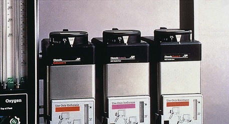
Plenum vaporizer (Fig. 2.17)
1. The case with the filling level indicator and a port for the filling device.
2. Percentage control dial on top of the case.
3. The bypass channel and the vaporization chamber. The latter has wicks or baffles to increase the surface area available for vaporization (Fig. 2.18).
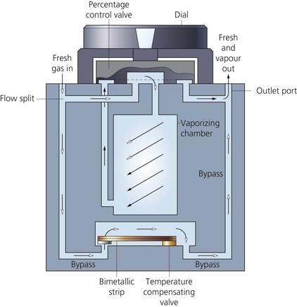
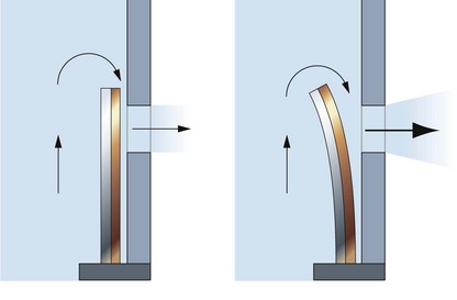
4. The splitting ratio is controlled by a temperature-sensitive valve utilizing a bimetallic strip (Fig. 2.19). The latter is made of two strips of metal with different coefficients of thermal expansion bonded together. It is positioned inside the vaporization chamber in the Tec Mk 2 whereas in Tec Mk 3, 4 and 5, it is outside the vaporization chamber. An ether-filled bellows is the temperature compensating device in the M&IE Vapamasta Vaporizer 5 and 6. The bellows contracts as the temperature of the vaporizer decreases.
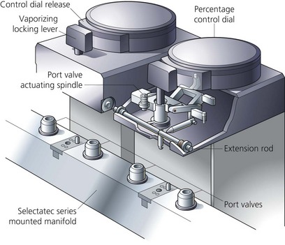
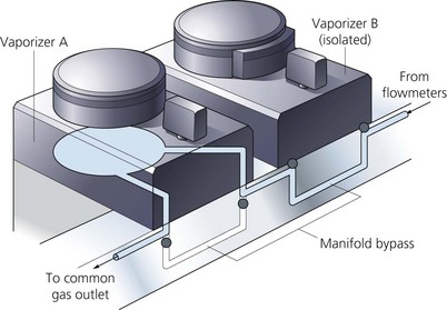
5. The vaporizers are mounted on the back bar (Fig. 2.20) using the interlocking Selectatec system (Fig. 2.21). The percentage control dial cannot be moved unless the locking lever of the system is engaged (in Mk 4 and 5). The interlocking extension rods prevent more than one vaporizer being used at any one time, preventing contamination of the one downstream (in Mk 4 and 5). The FGF only enters the vaporizer when it is switched on (Fig. 2.22).
Mechanism of action
1. The calibration of each vaporizer is agent-specific.
2. Fresh gas flow is split into two streams on entering the vaporizer. One stream flows through the bypass channel and the other, smaller stream, flows through the vaporizing chamber. The two gas streams reunite as the gas leaves the vaporizer.
3. The vaporization chamber is designed so that the gas leaving it is always fully saturated with vapour before it rejoins the bypass gas stream. This should be achieved despite changes in the FGF.
4. Full saturation with vapour is achieved by increasing the surface area of contact between the carrier gas and the anaesthetic agent. This is achieved by having wicks saturated by the inhalational agent, a series of baffles or by bubbling the gas through the liquid.
5. The desired concentration is obtained by adjusting the percentage control dial. This alters the amount of gas flowing through the bypass channel to that flowing through the vaporization chamber.
6. In the modern designs, the vapour concentration supplied by the vaporizer is virtually independent of the FGFs between 0.5 and 15 L/min.
7. During vaporization, cooling occurs due to the loss of latent heat of vaporization. Lowering the temperature of the agent makes it less volatile. In order to compensate for temperature changes:
a) the vaporizer is made of a material with high density and high specific heat capacity with a very high thermal conductivity, e.g. copper. Copper acts as a heat sink, readily giving heat to the anaesthetic agent and maintaining its temperature
b) a temperature sensitive valve (e.g. bimetallic strip or bellows) within the body of the vaporizer automatically adjusts the splitting ratio according to the temperature. It allows more flow into the vaporizing chamber as the temperature decreases.
8. The amount of vapour carried by the FGF is a function of both the saturated vapour pressure (SVP) of the agent and the atmospheric pressure. At high altitudes, the atmospheric pressure is reduced whereas the SVP remains the same. This leads to an increased amount of vapour whereas the saturation of the agent remains the same. The opposite occurs in hyperbaric chambers. This is of no clinical relevance as it is the partial pressure of the agent in the alveoli that determines the clinical effect of the agent.
Problems in practice and safety features
1. In modern vaporizers (Tec Mk 5), the liquid anaesthetic agent does not enter the bypass channel even if the vaporizer is tipped upside down due to an antispill mechanism. In earlier designs, dangerously high concentrations of anaesthetic agent could be delivered to the patient in cases of agent spillage into the bypass channel. Despite that, it is recommended that the vaporizer is purged with a FGF of 5 L/min for 30 min with the percentage control dial set at 5%.
2. The Selectatec system increases the potential for leaks. This is due to the risk of accidental removal of the O-rings with changes of vaporizers.
3. Minute volume divider ventilators exert back pressure as they cycle. This pressure forces some of the gas exiting the outlet port back into the vaporizing chamber, where more vapour is added. Retrograde flow may also contaminate the bypass channel. These effects cause an increase in the inspired concentration of the agent which may be toxic. These pressure fluctuations can be compensated for by:
a) long inlet port into the vaporizing chamber as in Tec Mk 3. This ensures that the bypass channel is not contaminated by retrograde flow from the vaporizing chamber
b) downstream flow restrictors: used to maintain the vaporizer at a pressure greater than any pressure required to operate commonly used ventilators
c) both the bypass channel and the vaporizing chamber are of equal volumes so gas expansion and compression are equal.
4. Preservatives, such as thymol in halothane, accumulate on the wicks of vaporizers with time. Large quantities may interfere with the function of the vaporizer. Thymol can also cause the bimetallic strip in the Tec Mk 2 to stick. Enflurane and isoflurane do not contain preservative.
5. A pressure relief valve downstream of the vaporizer opens at about 35 kPa. This prevents damage to flowmeters or vaporizers if the common gas outlet is blocked.
6. The bimetallic strip has been situated in the bypass channel since the Tec Mk 3. It is possible for the chemically active strip to corrode in a mixture of oxygen and the inhalational agent within the vaporizing chamber (Tec Mk 2).
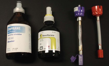
Vaporizer filling devices
These are agent-specific being geometrically coded (keyed) to fit the safety filling port of the correct vaporizer and anaesthetic agent supply bottle (Fig. 2.23). They prevent the risk of adding the wrong agent to the wrong vaporizer and decrease the extent of spillage. The safety filling system, in addition, ensures that the vaporizer cannot overflow. Fillers used for desflurane and sevoflurane have valves that are only opened when fully inserted into their ports. This prevents spillage.
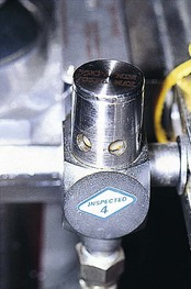
Non-return pressure relief safety valve
This is situated downstream of the vaporizers either on the back bar itself or near the common gas outlet (Fig. 2.24).
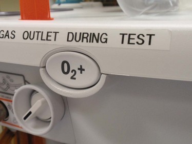
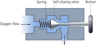
Emergency oxygen flush
This is usually activated by a non-locking button (Fig. 2.25). When pressed, pure oxygen is supplied from the outlet of the anaesthetic machine. The flow bypasses the flowmeters and the vaporizers. A flow of about 35–75 L/min at a pressure of about 400 kPa is expected. The emergency oxygen flush is usually activated by a non-locking button and using a self-closing valve. It is designed to minimize unintended and accidental operation by staff or other equipment. The button is recessed in a housing to prevent accidental depression.
Problems in practice and safety features
1. The high operating pressure and flow of the oxygen flush puts the patient at a higher risk of barotrauma.
2. When the emergency oxygen flush is used inappropriately, it leads to dilution of the anaesthetic gases and possible awareness.
3. It should not be activated while ventilating a patient using a minute volume divider ventilator.
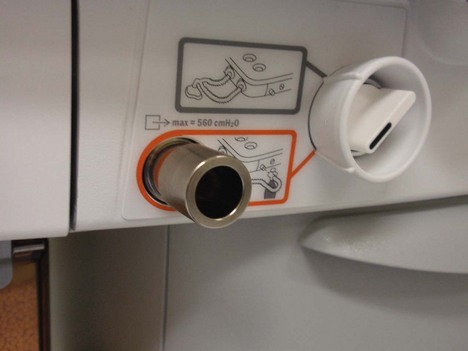
Compressed oxygen outlet(s)
One or more compressed oxygen outlets used to provide oxygen at about 400 kPa (Fig. 2.26). It can be used to drive ventilators or a manually controlled jet injector.
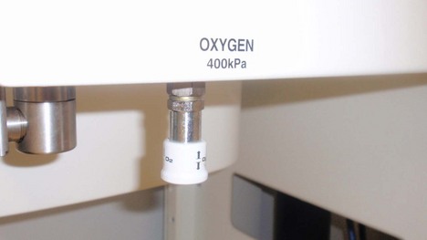
Fig. 2.26 Compressed oxygen outlet.
Oxygen supply failure alarm
There are many designs available (Fig. 2.27) but the characteristics of the ideal warning device are:
1. Activation depends on the pressure of oxygen itself.
2. It requires no batteries or mains power.
3. It gives an audible signal of a special character and of sufficient duration and volume to attract attention.
4. It should give a warning of impending failure and a further alarm that failure has occurred.
5. It should have pressure-linked controls which interrupt the flow of all other gases when it comes into operation. Atmospheric air is allowed to be delivered to the patient, without carbon dioxide accumulation. It should be impossible to resume anaesthesia until the oxygen supply has been restored.
6. The alarm should be positioned on the reduced pressure side of the oxygen supply line.
8. It is not affected by backpressure from the anaesthetic ventilator.
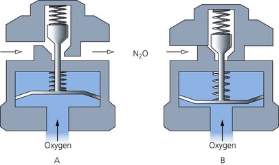
In modern machines, if the oxygen supply pressure falls below 200 kPa, the low-pressure supply alarm sounds. With supply pressures below 137 kPa, the ‘fail safe’ valve will interrupt the flow of other gases to their flowmeters so that only oxygen can be delivered (Fig. 2.28). The oxygen flow set on the oxygen flowmeter will not decrease until the oxygen supply pressure falls below 100 kPa.
Other modifications and designs
1. Desflurane vaporizer (Figs 2.30 and 2.31). Desflurane is an inhalational agent with unique physical properties making it extremely volatile. Its SVP is 664 mmHg at 20°C and, with a boiling point of 23.5°C at atmospheric pressure which is only slightly above normal room temperature, precludes the use of a normal variable-bypass type vaporizer. In order to overcome these physical properties, vaporizers with a completely different design from the previous Tec series are used despite the similar appearance. They are mounted on the Selectatec system.
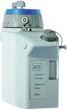
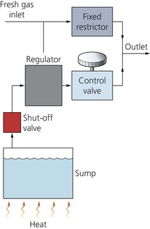
Fig. 2.31 A schematic diagram of the Tec Mk 6 vaporizer. (Reproduced with permission from Datex-Ohmeda.)
a) An electrically heated desflurane vaporization chamber (sump) with a capacity of 450 mL. The chamber requires a warm-up period of 5–10 minutes to reach its operating temperature of 39°C (i.e. above its boiling point) and a SVP of more than 1550 mmHg (about two atmospheric pressures). The vaporizer will not function below this temperature and pressure.
b) A fixed restriction/orifice is positioned in the FGF path. The FGF does not enter the vaporization chamber. Instead, the FGF enters the path of the regulated concentration of desflurane vapour before the resulting gas mixture is delivered to the patient.
c) A differential pressure transducer adjusts a pressure-regulating valve at the outlet of the vaporization chamber. The transducer senses pressure at the fixed restriction on one side and the pressure of desflurane vapour upstream to the pressure-regulating valve on the other side. This transducer ensures that the pressure of desflurane vapour upstream of the control valve equals the pressure of fresh gas flow at the fixed restriction.
d) A percentage control dial with a rotary valve adjusts a second resistor which controls the flow of desflurane vapour into the FGF and thus the output concentration. The dial calibration is from 0% to 18%.
e) The fixed restriction/orifice ensures that the pressure of the carrier gas within the vaporizer is proportional to gas flow. The transducer ensures that the pressure of desflurane vapour upstream of the resistor equals the pressure of FGF at the orifice. This means that the flow of desflurane out of the vaporizing chamber is proportional to the FGF, so enabling the output concentration to be made independent of FGF rate.
f) The vaporizer incorporates malfunction alarms (auditory and visual). There is a back-up 9-volt battery should there be a mains failure.
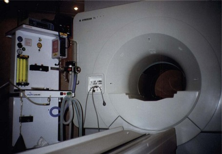
2. Since most of the anaesthetic machine is made from metal, it should not be used close to magnetic resonance imaging (MRI) scanner. Distorted readings and physical damage to the scanner are possible because of the attraction of the strong magnetic fields. Newly designed anaesthetic machines made of totally non-ferrous material solve this problem (Fig. 2.32).
3. Newly designed anaesthetic machines are more sophisticated than that described above. Many important components have become electrically or electronically controlled as an integrated system (Fig. 2.33). Thermistors can be used to measure the flow of gases. Gas flow causes changes in temperature which are measured by the thermistors. Changes in temperature are calibrated to measure flows of gases. Other designs measure flows using electronic flow sensors based on the principle of the pneumotachograph. Pressure difference is measured across a laminar flow resistor through which the gas flows. Using a differential pressure transducer, flow is measured and displayed on a screen in the form of a virtual graduated flowmeter, together with a digital display.
4. Quantiflex Anaesthetic Machine (Fig. 2.34). This machine has the following features:
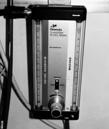
Fig. 2.34 Quantiflex Anaesthetic Machine.
a) Two flowmeters, one for oxygen and one for nitrous oxide, with one control knob for both flowmeters.
b) The oxygen flowmeter is situated to the right, whereas the nitrous oxide flowmeter is situated to the left.
c) The relative concentrations of oxygen and nitrous oxide are adjusted by a mixture control wheel. The oxygen concentration can be adjusted in 10% steps from 30% to 100%.
d) This design prevents the delivery of hypoxic mixtures.
e) It is mainly used in dental anaesthesia.
Some newly designed anaesthetic machines have an extra outlet with its own flowmeter to deliver oxygen to conscious or lightly sedated patients via a face mask. This can be used in patients undergoing surgery under regional anaesthesia with sedation.
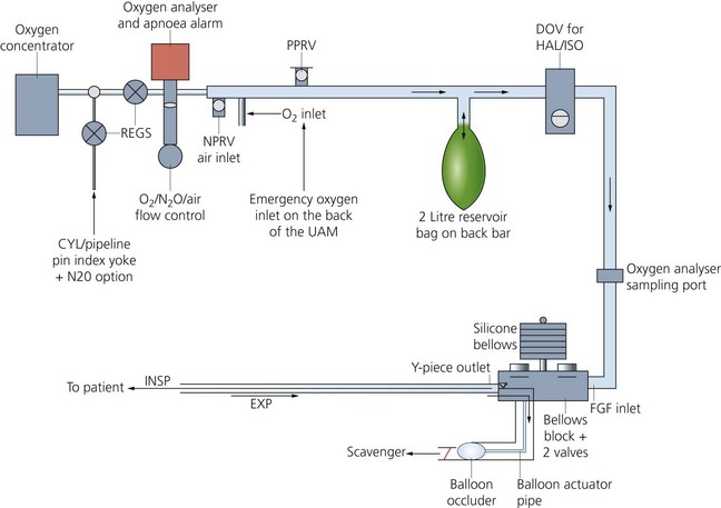
5. Universal Anaesthesia Machine (UAM) (Figs 1.23 and 2.35). This was developed to enable the provision of anaesthesia in poorly resourced countries where compressed gases and electricity supplies are unreliable. The UAM differs from standard anaesthetic machines by the use of an electrically powered oxygen concentrator (producing 10 L/min of 95% oxygen), drawover vaporizer, bellows and balloon valve. The UAM can function in both continuous flow and drawover modes, entraining air as necessary (e.g. if electricity supply to the concentrator fails), with the vaporizer functioning as normal. Alternatively, oxygen can be provided via cylinder, pipeline or the side emergency inlet. The UAM has two flowmeters, one for oxygen and the other for either nitrous oxide or air. A 2-L reservoir bag is positioned distal to the flowmeters on the back bar. A negative pressure valve allows entrainment of air (if the FGF is less than the patient’s minute ventilation) and a positive pressure relief valve prevents overpressure of the bag.
Anaesthesia in remote areas
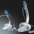
The apparatus used must be compact, portable and robust. The Triservice apparatus is suitable for use in remote areas where supply of compressed gases and vapours is difficult (Figs 2.36 and 2.37). The Triservice anaesthetic apparatus name derives from the three military services: Army, Navy and Air Force.
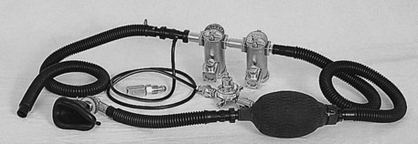
Fig. 2.36 The Triservice apparatus.
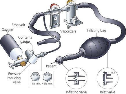
Components
1. A face mask with a non-rebreathing valve fitted.
2. A short length of tubing leading to a self-inflating bag.
3. A second length of tubing leading from the self-inflating bag to two Oxford Miniature Vaporizers (OMV).
4. An oxygen cylinder can be connected upstream of the vaporizers. A third length of tubing acts as an oxygen reservoir during expiration.
Mechanism of action
1. The Triservice apparatus can be used for both spontaneous and controlled ventilation.
a) The patient can draw air through the vaporizers. The exhaled gases are vented out via the non-rebreathing valve.
b) The self-inflating bag can be used for controlled or assisted ventilation.
2. The OMV is a draw-over vaporizer with a capacity for 50 mL of anaesthetic agent. The wick is made of metal with no temperature compensation features. There is an ethylene glycol jacket acting as a heat sink to help to stabilize the vaporizer temperature. The calibration scale on the vaporizer can be detached allowing the use of different inhalational agents. A different inhalational agent can be used after blowing air for 10 minutes and rinsing the wicks with the new agent. The vaporizer casing has extendable feet fitted.
3. The downstream vaporizer is traditionally filled with trichloroethylene to compensate for the absence of the analgesic effect of nitrous oxide.
Problems in practice and safety features
1. The vaporizers’ heat sink (ethylene glycol jacket) is not suitable for prolonged use at high gas flows. The vapour concentration decreases as the temperature decreases.
2. During use, accidental tipping of the vaporizer can spill liquid agent into the breathing system. The vaporizer is spillproof when turned off.
Eisenkraft J.B. Anaesthesia machine basics. Seminars in Anaesthesia. Perioperative Medicine and Pain. 2005;24:138–146.
MHRA. Medical device alert: anaesthetic vaporizers – all manufacturers (MDA/2010/052). Online. Available at http://www.mhra.gov.uk/Publications/Safetywarnings/MedicalDeviceAlerts/CON085024, 2010.
MHRA. Medical device alert: various models of anaesthetic carestations manufactured by GE Healthcare (MDA/2010/058). Online. Available at http://www.mhra.gov.uk/Publications/Safetywarnings/MedicalDeviceAlerts/CON087755, 2010.
MHRA. Anaesthetic machine e-learning module. Online. Available at http://www.mhra.gov.uk/ConferencesLearningCentre/LearningCentre/Deviceslearningmodules/Anaestheticmachines/index.htm, 2010.
NHS. Airway suction equipment. Online. Available at http://www.nrls.npsa.nhs.uk/resources/?entryid45=94845, 2011.
In the following lists, which of the following statements (a) to (e) are true?
1. Flowmeters in an anaesthetic machine:
a) N2O may be used in an O2 flowmeter without a change in calibration.
b) Flowmeters use a tube and bobbin.
a) Manual ventilation using a vaporizer in circle (VIC) causes a reduction in the inspired concentration of the inhalational agent.
b) A Tec Mark 3 vaporizer can be used as a VIC.
c) Gas flow emerging from the vaporizing chamber should be fully saturated with the inhalational agent.
d) The bimetallic strip valve in Tec Mark 5 is in the vaporizing chamber.
e) The inhalational agent concentration delivered to the patient gradually decreases the longer the vaporizer is used due to cooling of the agent.
3. Pressure gauges on an anaesthetic machine:
a) Use the Bourdon pressure gauge principle.
b) The pressure reflects accurately the cylinders’ contents for both oxygen and nitrous oxide.
c) Can be interchangeable between oxygen and nitrous oxide.
d) The same pressure gauge can be used for both cylinder and pipeline gas supply.
a) It is directly proportional to the square root of pressure.
b) Halving the radius results in a flow equivalent to a 16th of the original laminar flow.
c) It is related to the density of the fluid.
d) The flow is greatest in the centre.
e) Laminar flow changes to turbulent when Reynold’s number exceeds 2000.
5. Flowmeters on an anaesthetic machine:
a) They have an accuracy of ±2.5%.
b) They have a tapered tube with a narrow top.
c) Oxygen is the first gas to be added to the mixture at the back bar.
d) At high flows, the density of the gas is important in measuring the flow.
6. Concerning the Triservice apparatus:
a) Two plenum vaporizers are used.
b) It can be used for both spontaneous and controlled ventilation.
c) An inflating bag and a one-way valve are used.
d) The Oxford Miniature Vaporizer has a metal wick and a heat sink.
a) They are only used to reduce the pressure of gases.
b) They maintain a gas flow at a constant pressure of about 400 kPa.
c) Their main purpose is to protect the patient.
d) Relief valves open at 700 kPa in case of failure.
e) Flow restrictors can additionally be used in pipeline supply.
8. The safety features found in an anaesthetic machine include:
9. The non-return valve on the back bar of an anaesthetic machine between the vaporizer and common gas outlet:
1. Flowmeters in an anaesthetic machine:
a) False. The flowmeters in an anaesthetic machine are calibrated for the particular gas(es) used taking into consideration the viscosity and density of the gas(es). N2O and O2 have different viscosities and densities so unless the flowmeters are recalibrated, false readings will result.
b) True. They are constant pressure, variable orifice flowmeters. A tapered transparent tube with a lightweight rotating bobbin. The bobbin is held floating in the tube by the gas flow. The clearance between the bobbin and the tube wall widens as the flow increases. The pressure across the bobbin remains constant as the effect of gravity on the bobbin is countered by the gas flow.
d) False. The flowmeters do not have a linear scale. There are different scales for low and high flow rates.
e) True. At low flows, the flowmeter acts as a tube, as the clearance between the bobbin and the wall of the tube is longer and narrower. This leads to laminar flow which is dependent on the viscosity (Poiseuille’s law). At high flows, the flowmeter acts as an orifice. The clearance is shorter and wider. This leads to turbulent flow which is dependent on density.
a) False. During manual (or controlled) ventilation using a VIC vaporizer, the inspired concentration of the inhalational agent is increased. It can increase to dangerous concentrations. Unless the concentration of the inhalational agent(s) is measured continuously, this technique is not recommended.
b) False. As the patient is breathing through a VIC vaporizer, it should have very low internal resistance. The Tec Mark 3 has a high internal resistance because of the wicks in the vaporizing chamber.
c) True. This can be achieved by increasing the surface area of contact between the carrier gas and the anaesthetic agent. Full saturation should be achieved despite changes in fresh gas flow. The final concentration is delivered to the patient after mixing with the fresh gas flow from the bypass channel.
d) False. The bimetallic strip valve in the Tec Mk 5 is in the bypass chamber. The bimetallic strip has been positioned in the bypass chamber since the Tec Mk 3. This was done to avoid corrosion of the strip in a mixture of oxygen and inhalational agent when positioned in the vaporizing chamber.
e) False. The concentration delivered to the patient stays constant because of temperature compensating mechanisms. This can be achieved by:
• using a material with high density and high specific thermal conductivity (e.g. copper) which acts as a heat sink readily giving heat to the agent and maintaining its temperature
• a temperature-sensitive valve within the vaporizer which automatically adjusts the splitting ratio according to the temperature, so if the temperature decreases due to loss of latent heat of vaporization, it allows more flow into the vaporizing chamber.
3. Pressure gauges on an anaesthetic machine:
a) True. A pressure gauge consists of a coiled tube that is subjected to pressure from the inside. The high-pressure gas causes the tube to uncoil. The movement of the tube causes a needle pointer to move on a calibrated dial indicating the pressure.
b) False. Oxygen is stored as a gas in the cylinder hence it obeys the gas laws. The pressure changes in an oxygen cylinder accurately reflect the contents. Nitrous oxide is stored as a liquid and vapour so it does not obey Boyle’s gas law. This means that the pressure changes in a nitrous oxide cylinder do not accurately reflect the contents of the cylinder.
c) False. The pressure gauges are calibrated for a particular gas or vapour. Oxygen and nitrous oxide pressure gauges are not interchangeable.
d) False. Cylinders are kept under much higher pressures (13 700 kPa for oxygen and 5400 kPa for nitrous oxide) than the pipeline gas supply (about 400 kPa). Using the same pressure gauges for both cylinders and pipeline gas supply can lead to inaccuracies and/or damage to pressure gauges.
e) True. Colour-coding is one of the safety features used in the use and delivery of gases in medical practice. In the UK, white is for oxygen, blue for nitrous oxide and black for medical air.
a) False. Laminar flow is directly proportional to pressure. Hagen–Poiseuille equation: Flow ∝ pressure × radius4/viscosity × length.
b) True. From the above equation, the flow ∝ radius4.
c) False. Laminar flow is related to viscosity. Turbulent flow is related to density.
d) True. Laminar flow is greatest in the centre at about twice the mean flow rate. The flow is slower nearer to the wall of the tube. At the wall the flow is almost zero.
e) True. Reynold’s number is the index used to predict the type of flow, laminar or turbulent. Reynold’s number = velocity of fluid × density × radius of tube/viscosity. In laminar flow, Reynold’s number is <2000. In turbulent flow, Reynold’s number is >2000.
5. Flowmeters on an anaesthetic machine:
a) True. The flowmeters on the anaesthetic machine are very accurate with an accuracy of ±2.5%.
b) False. The flowmeters on an anaesthetic machine are tapered tubes. The top is wider than the bottom.
c) False. Oxygen is the last gas to be added to the mixture at the back bar. This is a safety feature in the design of the anaesthetic machine. If there is a crack in a flowmeter, a hypoxic mixture may result if oxygen is added first to the mixture.
d) True. At high flows, the flow is turbulent which is dependent on density. At low flows, the flow is laminar which is dependent on viscosity.
e) True. When a ball is used, the reading is taken from the midpoint.
6. Concerning the Triservice apparatus:
a) False. In the Triservice apparatus, two Oxford Miniature, draw-over, Vaporizers (OMV) are used. Plenum vaporizers are not used due to their high internal resistance. The OMV is light weight and, by changing its calibration scale, different inhalational agents can be used easily.
b) True. The system allows both spontaneous and controlled ventilation. The resistance to breathing is low allowing spontaneous ventilation. The self-inflating bag provides the means to control ventilation.
d) True. The OMV has a metal wick to increase area of vaporization within the vaporization chamber. The heat sink consists of an ethylene glycol jacket to stabilize the vaporizer temperature.
e) True. Supplementary oxygen can be added to the system from an oxygen cylinder. The oxygen is added to the reservoir proximal to the vaporizer(s).
a) False. Pressure regulators are used to reduce pressure of gases and also to maintain a constant flow. In the absence of pressure regulators, the flowmeters need to be adjusted regularly to maintain constant flows as the contents of the cylinders are used up. The temperature and pressure of the cylinder contents decrease with use.
b) True. Pressure regulators are designed to maintain a gas flow at a constant pressure of about 400 kPa irrespective of the pressure and temperature of the contents of the cylinder.
c) False. Pressure regulators offer no protection to the patient. Their main function is to protect the anaesthetic machine from the high pressure of the cylinder and to maintain a constant flow of gas.
d) True. In situations where the pressure regulator fails, a relief valve that opens at 700 kPa prevents the build up of excessive pressure.
e) True. Flow restrictors can be used in a pipeline supply. They are designed to protect the anaesthetic machine from pressure surges in the system. They consist of a constriction between the pipeline supply and the anaesthetic machine.
8. The safety features found in an anaesthetic machine include:
a) True. This is an essential safety feature in the anaesthetic machine. The ideal design should operate under the pressure of oxygen itself, give a characteristic audible signal, be capable of warning of impending failure and give a further alarm when failure has occurred, be capable of interrupting the flow of other gases and not require batteries or mains power to operate.
b) True. The flowmeters are colour-coded and also the shape and size of the oxygen flowmeter knob is different from the nitrous oxide knob. This allows the identification of the oxygen knob even in a dark environment.
c) False. The vaporizer level can be monitored by the anaesthetist. This is part of the anaesthetic machine checklist. There is no alarm system.
d) True. A ventilator disconnection alarm is essential when a ventilator is used. They are also used to monitor leaks, obstruction and malfunction. They can be pressure and/or volume monitoring alarms. In addition, clinical observation, end-tidal carbon dioxide concentration and airway pressure are also ‘disconnection alarms’.
e) False. Only one vaporizer can be used at any one time. This is due to the interlocking Selectatec system where interlocking extension rods prevent more than one vaporizer being used at any one time. These rods prevent the percentage control dial from moving, preventing contamination of the downstream vaporizer.
9. The non-return valve on the back bar of an anaesthetic machine between the vaporizer and common gas outlet:
a) True. Minute volume divider ventilators exert back pressure as they cycle. This causes reversal of the fresh gas flow through the vaporizer. This leads to an uncontrolled increase in the concentration of the inhalational agent. Also the back pressure causes the fluctuation of the bobbins in the flowmeters as the ventilator cycles. The non-return valve on the back bar prevents these events from happening.
b) True. The non-return valve on the back bar opens when the pressure in the back bar exceeds 35 kPa. Flowmeters and vaporizer components can be damaged at higher pressures.
c) True. By preventing the effects of back pressure on the flowmeters and vaporizer as the minute volume divider ventilator cycles, the non-return valve on the back bar provides some protection to the patient. The flows on the flowmeters and the desired concentration of the inhalational agent can be accurately delivered to the patient.
e) False. The non-return valve on the back bar of the anaesthetic machine opens at a pressure of 35 kPa.
10. The oxygen emergency flush on an anaesthetic machine:
a) False. 35–75 L/min can be delivered by activating the oxygen emergency flush on the anaesthetic machine.
b) False. The inappropriate use of the oxygen flush during anaesthesia increases risk of awareness (a 100% oxygen can be delivered) and barotrauma to the patient (because of the high flows delivered).
d) True. This can happen by diluting the anaesthetic mixture; see b).
e) False. Because of the high FGF (35–70 L/min), the minute volume divider ventilator does not function appropriately.