Supine Approach to Hip Arthroscopy

Published on 11/04/2015 by admin

Filed under Orthopaedics

Last modified 22/04/2025

Print this page

rate 1 star rate 2 star rate 3 star rate 4 star rate 5 star
Your rating: none, Average: 0 (0 votes)

This article have been viewed 3153 times

CHAPTER 9 Supine Approach to Hip Arthroscopy

Introduction

Two standard positions have been used for hip arthroscopy: lateral and supine. The supine approach is often favored for its familiar positioning with easy reference to the anatomic landmarks to which most surgeons are accustomed. The maneuverability and functionality of the arthroscopic equipment are also most similar to that used for other arthroscopic procedures with patients in the supine position. The anatomic orientation required for this position appears to be easier to attain from the surgeon’s standpoint than that required for the lateral position. With the patient in the supine position, the operative extremity can be mobilized (i.e., dynamic testing in hip flexion–extension and rotation) during the procedure, and it also allows for capsular relaxation and the dynamic visualization of the joint and the peripheral compartment. With the supine approach, traction may be applied with the use of a standard hip fracture table or other device, whereas the lateral position requires a more specialized setup. In addition to the position being more familiar to classic total joint surgeons, the main benefit of the lateral position is that it uses gravity more effectively to allow the soft tissue to fall away from the greater trochanter as the primary landmark for instrumentation. This is most significant for the larger, moderately obese patient. However, some feel that the lateral approach is more time consuming and that using fluoroscopic imaging with a C-arm may be insufficient to get around an obese patient under the operating room table. In the end, both of these positions are effective, with surgeon preference and patient comfort being the determining factors as far as which one is chosen. Our preferred method is the supine position for the reasons outlined previously. This chapter describes our general surgical technique for patients in the supine position.

General considerations

The hip joint is not a true space. To perform hip arthroscopy of the central compartment, which is the area within the acetabulum, traction must be applied. Usually 8 mm to 12 mm of joint space opening is required to perform hip arthroscopy safely. If there is too little traction, then iatrogenic injury to the articular cartilage may occur while trying to travel through the joint. If there is too much traction, then there is increased potential risk of injury to the neural structures around the joint and the perineum as well as risk to the knee, foot, and ankle. Traction may be applied with the use of a standard fracture table or with the use of other commercially available attachments that have been devised for regular operating room tables, although some authors have reported using weight over the end of a standard operating room table as a means of applying traction. Usually 25 lb to 50 lb of force is needed to apply adequate traction for hip arthroscopy.

To facilitate traction, we prefer the use of general anesthesia with paralysis. This allows for adequate traction without undue force to reduce the risk of injury to the nerves and the perineum. Arthroscopy of the hip may be performed with spinal anesthesia if there is adequate muscle relaxation. As an adjunct to general anesthesia, we have also used a lumbar plexus block to reduce the amount of narcotic intraoperatively, thereby reducing the amount of nausea postoperatively and the amount of pain during the immediate postoperative period (usually 12 to 18 hours). We prefer hypotensive anesthesia to reduce bleeding within the joint, thereby allowing for better visualization.

Hip arthroscopy is facilitated by the use of specialized instrumentation. Although extra-long arthroscopes and cannulas may be used, there is a risk of damage to these instruments. A standard-length hip arthroscope with a cannula that has a modified bridge is most commonly used, and this has been used almost exclusively by the senior author for the past 15 years. Only in the particularly obese patient is the extra-long arthroscopic lens needed. Cannulated hip arthroscopy systems that make use of Nitinol wires and blunt trochars have significantly reduced complications and aided in the development of arthroscopy portals. Many specialized extra-long instruments have been developed to perform therapeutic hip arthroscopy, including longer arthroscopic motorized shavers and burrs. Some shavers are curved to help facilitate access to areas around the femoral head. Other instruments include modified hand instrumentation, such as arthroscopic knives, rongeurs, meniscal biters (i.e., forward and backward, straight and upbiting), curettes, and even microfracture awls. Radiofrequency devices that are narrow and that bend at the tip are quite useful for tissue ablation and tissue shrinkage. In addition, instrumentation for labral repair (e.g., suture anchors that fit through narrow cannulas) is also available.

The senior surgeon generally uses 5.0-mm cannulas for the three central compartment portals, although, in tight hips with limited distraction, a 4.5-mm cannula may be used. However, when using gravity inflow for fluid, the fluid dynamics with the 4.5-mm cannula are suboptimal, and the cannula is changed, when possible. Alternatively, the introduction of irrigation fluid with a pump may overcome the limited dynamics of the smaller cannula. Frequently, 5.5-mm or 5.6-mm cannulas are necessary for the introduction of many instruments, including labral repair instruments, curettes, microfracture awls, and some labral biters. Alternatively, a slotted cannula (i.e., half-pipe) can allow for the maintenance of the portal while allowing larger instruments to be introduced (e.g., curved shaver, microfracture awl).

Saline or lactated Ringer’s solution with epinephrine is usually used during hip arthroscopy as irrigation fluid. Irrigation fluid is introduced with the use of a gravity inflow system to reduce the risk of clinically significant fluid extravasation, because there have been reported cases of intra-abdominal fluid extravasation that have resulted in cardiac arrest. Visualization is enhanced with the use of hypotensive anesthesia and 5.0-mm or larger cannulas. However, on occasion, a pump is needed to perform arthroscopy (in the senior author’s experience, this happens with less than 1% of cases).

To ensure the adequate visualization of the entire joint, the senior author prefers using three portals for central compartment arthroscopy on all patients and using both the 30-degree and 70-degree lenses in all three central compartment portals. To help with the maneuverability of both the arthroscope and the instrumentation, capsulotomies made with an arthroscopic knife or a radiofrequency probe do allow for significant freedom for access and visualization.

Surgical technique

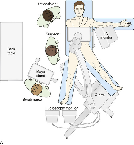
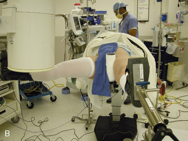
For the supine position technique, the patient is given a general anesthetic that provides muscle relaxation. Paralysis is recommended, because this allows less force to be used to distract the hip, with the purpose of reducing the risk of pudendal nerve injury from pressure between the pelvis and the perineal post of the traction table. The patient is placed supine on the fracture table with both feet secured to traction boots or mobile spars, depending on the specific table used. A well-padded perineal post is placed, and the patient is brought into position so that the post is firmly situated against the perineum and lateralized toward the operative hip, with care taken to protect the genitalia. The operative leg is positioned in 10 degrees of abduction, neutral flexion–extension, and neutral rotation. The nonoperative extremity is positioned in 45 degrees to 60 degrees of abduction, neutral flexion–extension, and neutral rotation to serve as countertraction for lateralization. Gentle traction is applied to the abducted nonoperative leg, which lateralizes the patient’s pelvis and results in the perineal post resting on the inner upper thigh of the operative extremity (Figure 9-1). This allows for the pressure of the perineal post to be diverted away from the perineum itself to minimize the risk of neuropraxia to the pudendal nerve as traction is applied to the operative leg. In addition—and quite important—this also helps to generate the appropriate vector of force for a uniform distraction both laterally and distally (Figure 9-2). Traction to the operative leg straight distally would be met with unnecessary resistance to overcome the inferior transverse acetabular ligament. Lateralization of the hip with the use of the post helps to pull the femoral head laterally and distally from the socket without having to overcome the ligament as a barrier to distal translation.
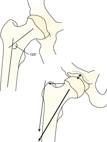
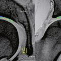
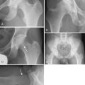
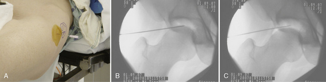
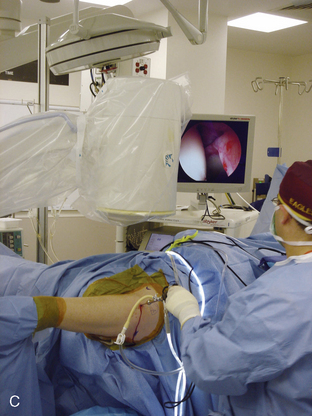
After the patient has been positioned appropriately and slight traction has been applied to the nonoperative extremity, traction on the operative limb can be applied. This should be incremental, and it can be monitored with serial images from an image intensifier (i.e., C-arm). A tensiometer can also be used; however, the senior author has not found this to be useful. Jim Glick has shown that the risk of nerve injury as assessed by somatosensory evoked potentials is associated with the duration of traction rather than the amount of traction (Glick, personal communication). Thus, the absolute amount of traction is apparently not important. Some surgeons use the tensiometer to evaluate any changes in tension. We use the fluoroscopic image intensifier routinely; we bring the base of the machine in from the foot of the table in between the patient’s abducted legs, and we center the column over the operative hip (see Figure 9-1). Incremental traction is then applied until approximately 8 mm to 10 mm of femoroacetabular joint distraction is generated. The area of the proposed anterolateral portal is identified and marked; the area around this proposed portal site is prepared with Betadine solution; and a spinal needle is then used to enter the hip joint to verify the correct path of the anterolateral portal, to ease joint access, and to perform an air arthrogram to release negative intra-articular pressure. In a cadaver study, Dienst and colleagues demonstrated that positioning the hip in 20 degrees of flexion and performing an air arthrogram (i.e., disrupting the vacuum seal and distending the hip joint) reduced the amount of traction required to distract the joint for safe entry, thereby further reducing the risk of neuropraxia. The needle is placed from the intended anterolateral portal with the guidance of the fluoroscopic image intensifier (Figure 9-3). The needle needs to enter the central compartment to effectively reduce the intra-articular pressure. We have shown that placing the needle onto the femoral neck does not release the negative intra-articular pressure within the joint. Care is taken to keep the spinal needle close to the femoral head (to reduce the risk of injury to the labrum) and to keep the longer part of the tip away from the femoral head. When the suction seal is broken, the joint will open more widely. The needle position relative to the femoral head is evaluated before and after the seal is broken. If the needle moves proximally when the negative pressure is released, the labrum may have been violated by the needle. If the needle moves with the femoral head, the labrum has likely not been injured.

Central compartment

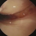
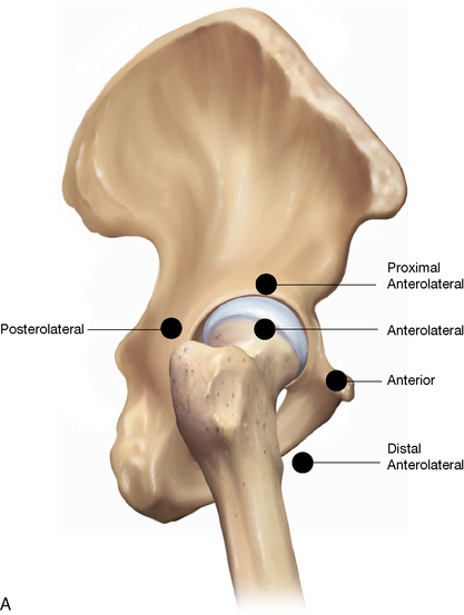
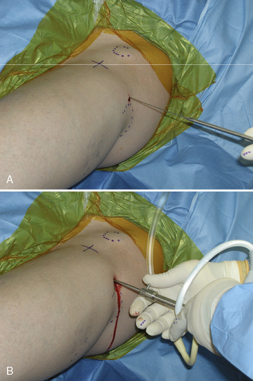
The anterolateral portal (Figure 9-4) is started approximately 1 cm anterior to the superior aspect of the anterior border of the greater trochanter. The needle is placed nearly parallel to the floor and angled toward the sourcil of the acetabulum, between the labrum and the distracted femoral head (see Figure 9-3, B). Avoiding the labrum is the key aspect of this part of the procedure. This can be optimized by careful visualization with the C-arm and by trying to keep the needle closer to the femoral head. The apex of the needle is kept away from the femoral head to help avoid injury to the femoral head articular cartilage. If the needle is near the acetabulum and does not pass easily after the puncture of the capsule, then it is likely within the substance of the labrum; it must be withdrawn and carefully redirected. After the needle is placed appropriately, the obturator of the spinal needle may be removed to allow for the inflow of air. This air arthrogram will verify appropriate placement, reduce the amount of traction required, and further increase the joint space produced by the traction with the same amount of force (see Figure 9-3, B and C). When this procedure is completed, the spinal needle is removed, the traction is released, and the patient’s hip can then be prepped and draped from the pelvis to the knee.

image image image

Figure 9–4 A, Schematic representation of where the three portals for hip arthroscopy begin. B, Schematic representation of the pathways of these three portals. C, The operating theater after the anterolateral portal has been established.

Redrawn from Safran MR. Hip Arthroscopy—The Basics. In: Weisel S ed. Operative Techniques in Orthopaedic Surgery. Lippincott Williams and Wilkins; Philadelphia; 2010.

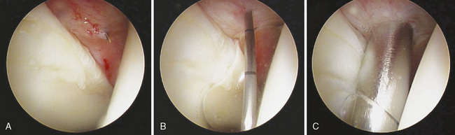
When the patient has been draped, the traction can be reapplied and verified with the C-arm, and then the anterolateral portal is created. Once again, place the spinal needle into the hip joint by following the same format and path. After the needle has been verified with the arthroscope to be intra-articular within the capsule and not damaging the labrum or articular cartilage, a guidewire is placed through the spinal needle. The spinal needle is then removed, leaving the guidewire in the place. A scalpel with a No. 11 blade is used to make a 5-mm incision over the guidewire. The cannulated trocar system is then used to place the arthroscope. Slowly and with controlled pressure and twisting to pierce the hip capsule, the blunt cannulated trocar is then introduced over the guidewire; this will provide moderate resistance (Figure 9-5). Care must be taken to not advance the guidewire too far or to bend the guidewire when inserting the cannula, because this may fracture the guidewire. Sharp trochars are discouraged, because this may cause iatrogenic injury to the joint. Trochar and sheath entry into the joint can be visualized with the C-arm. After getting inside of the joint, the blunt obturator and guidewire are removed, and an arthroscope with a 70-degree lens is introduced. When a clear picture is obtained, a cursory visualization of the hip joint may be conducted. The anterior portal is usually made right after the anterolateral portal is achieved. The anterior portal is made with the guidance of arthroscopic visualization to reduce the risk of iatrogenic injury to the acetabular or labral cartilage. Some surgeons insufflate fluid into the joint after the spinal needle for the anterolateral portal is introduced to allow for joint distention. The senior author does not do this and in fact does not run fluid into the joint until the spinal needle for the second portal has been established. There is often blood in the joint after distraction and capsular injury from the entry into the joint. With no outflow of fluid, insufflation of the joint will result in cloudy visualization or obstructed visualization through the bloody fluid. Thus, the second portal is created while the joint is dry.

Generally, we create the second (anterior) portal before performing a complete evaluation of the hip. The second portal is made under arthroscopic and fluoroscopic visualization to ensure that the labral and articular cartilage is not damaged with the introduction of the needle, trochar, and cannula for the second portal. After the second portal is made (usually the anterior portal), the arthroscope is placed into the cannula of the second portal to allow for the visualization of the initial (anterolateral) portal to ensure that the labrum was not injured with the creation of this first portal, which was placed under fluoroscopic visualization only. If the labrum was not injured, the arthroscope is replaced in the anterolateral portal cannula, and attention is turned to making the third portal and starting the complete diagnostic arthroscopy. If the labrum was injured during the introduction of the first portal, then the cannula is repositioned with the use of arthroscopic and fluoroscopic guidance.

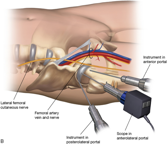
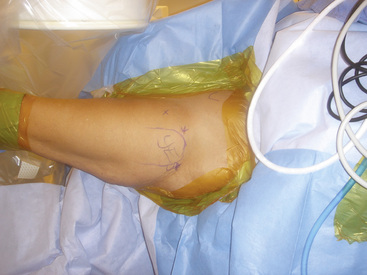
Next, the second portal is created; this is an anterior working and visualization portal. There are several described locations for the introduction of the anterior portal. One of the more common places for the anterior portal is at the intersection of a line drawn caudally from the anterior superior iliac spine and a perpendicular line drawn from the tip of the greater trochanter (see Figures 9-4 and 9-5). This portal carries the risk of injury to the lateral femoral cutaneous nerve (because of this superficial nerve’s intimate proximity to the portal) and to the rectus femoris. Our current preferred location for the anterior portal was described by Philippon (personal communication, 2007) and can be considered a mid-anterior portal. This portal is located 6 cm to 8 cm distal and anteromedial to the anterolateral portal at a 45-degree angle (Figure 9-6). This portal minimizes the risk of injury to the lateral femoral cutaneous nerve and the rectus femoris. In general, the different anterior portals are very near the arborization of the lateral femoral cutaneous nerve. Therefore, care must be taken when making this portal so that the skin incision remains superficial, with the No. 11 scalpel blade being used to reduce the risk of injury to the lateral femoral cutaneous nerve. The method for creating this portal is identical to that of creating the anterolateral; however, now the spinal needle may be visualized with the arthroscope in the anterolateral portal when the needle enters the joint, and care must be taken to pierce the capsule while avoiding injury to the labrum and the chondral surface (Figure 9-7). The spinal needle, the guidewire, and the subsequent trochar with cannula sheath all can be visualized with the arthroscope during entry to help avoid injury to the labrum and the articular cartilage. With this portal established, the arthroscope may be exchanged in this anterior portal to visualize the anterolateral portal placement to verify that no iatrogenic damage has occurred to the labrum. If the anterolateral portal is disrupting the labrum, it can now be redirected with the help of visualization from the anterior portal.

The posterolateral portal is the third and final standard portal for visualizing the central intra-articular compartment. Some surgeons do not routinely make a posterolateral portal, or, if they do, it serves as an inflow portal. The senior author prefers to use all three central compartment portals routinely to allow for the complete visualization of all structures in the hip joint from multiple perspectives. This portal is created in the same fashion as the other portals, and it is started 1 cm posterior to the posterosuperior border of the greater trochanter and in line with the anterolateral portal. The spinal needle can be directly visualized arthroscopically when it enters the joint through the joint capsule, and it should be placed in a convergent fashion with the arthroscope in the anterolateral portal. Leg position is important when making this portal. If the lower extremity is in external rotation, the posteriorly positioned greater trochanter results in a sharper angle for the spinal needle, thereby increasing the risk of injury to the sciatic nerve. Flexion of the hip also draws the sciatic nerve closer to the joint, which also increases risk of injury. With this final portal established, the arthroscope may be used to visualize the central compartment from each portal and to treat the observed pathology.

The 70-degree arthroscope lens is best used for examining the peripheral aspect of the central compartment (i.e., labrum, labral–chondral interface, acetabular rim, and peripheral femoral head), whereas the 30-degree arthroscope lens will provide better visualization of the central femoral head, the deep acetabular fossa, and the ligamentum teres. The 30-degree arthroscope lens is the senior author’s preferred lens to use in the peripheral extra-articular compartment for the treatment of such conditions as femoroacetabular impingement, synovial chondromatosis, and the removal of loose bodies.

Peripheral compartment

The peripheral compartment can be accessed through a variety of portals. The senior author prefers to use the same anterolateral portal incision and one additional portal to access the peripheral compartment and to treat any pathology. For the majority of problems in the peripheral compartment, the senior author prefers flexing the patient’s hip 20 degrees to 45 degrees to reduce tension from the anterior capsule and ligaments to assist with access and the mobility of the instrumentation in this area. The scope can be brought into the peripheral compartment via the anterior or anterolateral portal while the traction is removed from the extremity. Alternatively, a new capsulotomy may be made with the use of the spinal needle–guidewire– cannulated trochar system. With the use of the same anterolateral portal, the blunt obturator and arthroscope cannula are redirected inferiorly to the anterior femoral neck, which can be guided by feel and with the assistance of the C-arm. After the arthroscope is in place, it can be introduced, and the peripheral compartment can then be visualized. A second accessory working portal can be created in line with the anterolateral portal, approximately 4 cm to 7 cm distal. This typically requires the introduction of the spinal needle that enters the peripheral compartment capsule laterally; the needle is then exchanged for the guidewire, which is then exchanged for the cannulated trochar with sheath.

The senior author accesses the peripheral compartment for femoral acetabular impingement differently. The anterolateral portal skin incision is used, and the blunt trochar with cannula sheath is introduced to the lateral apex of the femoral head; this spot is outside of the joint capsule. A proximal anterolateral portal is then made, 4 cm proximal to but in line with the anterolateral portal. A 5.0-mm or 5.5-mm aggressive shaver is introduced through this proximal anterolateral portal. The tip of the shaver and the tip of the arthroscope should be next to each other at the lateral aspect of the femoral head outside of the capsule, as described in the senior author’s chapter about the arthroscopic management of cam impingement. The aggressive oscillating shaver is used to penetrate the lateral aspect of the capsule with the use of fluoroscopic and then arthroscopic visualization. Ultimately, with the help of arthroscopic visualization, a 1-cm to 1.5-cm window can be created in the lateral capsule; the peripheral compartment can be accessed through this opening.

Loose bodies may be removed from this accessory portal, or a high-speed burr may be placed for the performance of an osteoplasty for femoral head–neck junction lesions associated with femoroacetabular impingement. From this compartment, structures such as the labrum, the medial synovial fold, the capsular reflection, and the zona orbicularis can be visualized. These landmarks are useful for identifying other areas of pathology, such as the iliopsoas bursa and the tendon.

Annotated references

Byrd J.W.T. Hip arthroscopy utilizing the supine position. Arthroscopy. 1994;10:275-280.

Twenty patients treated for mechanical hip pain with arthroscopic procedures are described, including a technique for hip arthroscopy in the supine position and portal positioning. Excellent visualization was achieved in all cases and no major complications were encountered. Two transient neuropraxias of the pudendal nerve are reported..

Byrd J.W.T. The supine position. In: Byrd J.W.T., editor. Operative hip arthroscopy. New York: Thieme Publishers; 1998:123-138.

The supine positioning technique is described in this comprehensive textbook covering the evaluation and arthroscopic treatment of non-arthritic hip pathology. Safe positioning, portal placement, and basic arthroscopic technique is described..

Byrd J.W.T., Pappas J.N., Pedley M.J. Hip arthroscopy: an anatomic study of portal placement and relationship to extra-articular structures. Arthroscopy. 1995;11:418-423.

Eight fresh cadaveric paired hip specimens were dissected after placing Steinmann pins into the hip joint to simulate placement of portal sites. Neurovascular structures potentially at risk were evaluated for proximity to the portals. The anterior portal was found to be on average 0.3 cm from at least one of the branches of the lateral femoral cutaneous nerve. The superior gluteal nerve and sciatic nerves averaged 4.4 cm and 2.9 cm away from their respective portals..

Dienst M., Seil R., Gödde S., Brang M., Becker K., Georg T., Kohn D. Effects of traction, distention, and joint position on distraction of the hip joint: an experimental study in cadavers. Arthroscopy. 2002;18(8):865-871.

Eight cadaveric hip joints were evaluated in the supine position on a fracture table with applied traction. Joint distraction was improved up to a 2.25-fold increase in distraction for the same amount of applied force by allowing distention of the hip joint from disrupting the negative pressure seal and allowing distention with air. Better distraction was also identified at 20 degrees of flexion. The authors concluded that air distention can avoid excessive traction forces and reduce the risk of neurologic injuries..