[level-membership-for-neurosurgery-category]
Chapter 177 Stabilization of the Subaxial Cervical Spine (C3–C7)
Fusions by anterior approaches have been widely used in cervical spine injuries, allowing anterior decompression of the spinal column. Anterior fusion techniques were first introduced in 1955 by Smith and Robinson1 and then popularized by Cloward.2
The first application of a metal plate as a supplement to an anterior bone graft in cases of cervical dislocation was performed in 1975 by Herrmann.3 In 1980, Böhler4 also used small plates as proposed by Orozco and Llovet.5 In 1980 Caspar subsequently popularized the use of anterior cervical plates, resulting in more widespread use of Caspar plating6,7 in the mid-1980s in both Europe and the United States.8
Anterior Stabilization Techniques
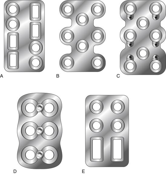
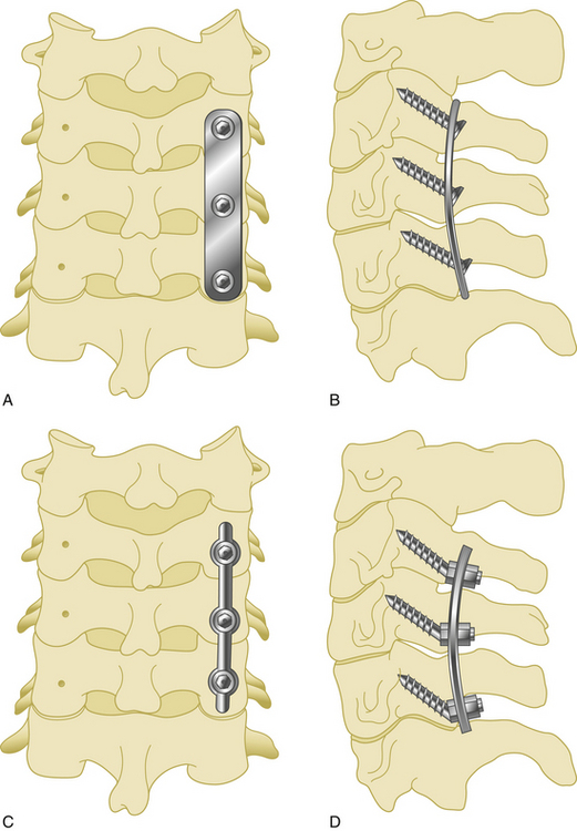
Anterior cervical plates have significantly changed since their early application in cervical trauma. They are now commonplace in anterior cervical decompression and fusion (ACDF) procedures, especially in cases requiring decompression of two or more levels. Routine use for the treatment of cervical spondylosis has caused plate design to change significantly in recent years. The first anterior cervical plates were unlocked and required bicortical purchase. Anterior cervical plates with constrained designs and locking plate–screw head connections then came into favor.9 The latest plates are semiconstrained dynamic plates that allow some movement in rotation and translation (Fig. 177-1).
Biomechanics of Cervical Plates
Screw choice and insertion technique also affect the biomechanical properties of anterior plating. For instance, hollow screws with small holes on the shaft were developed to allow improved osteointegration at the screw–bone interface.10 They were removed from the market because of high screw fracture rates and increased difficulty of removal.
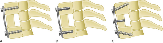
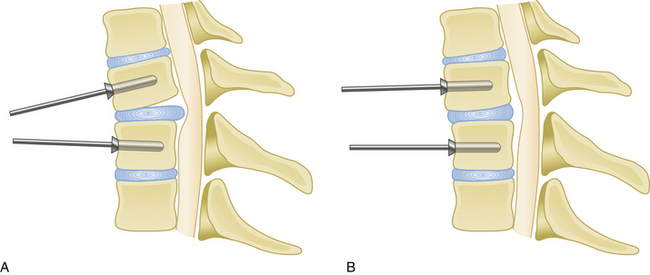
Medial or lateral angulation of anterior screws during insertion results in a triangulation in the axial plane, whereas cranial and caudal angulation results in sagittal plane triangulation. Varying the angle of trajectory provides improved construct strength and lessens the risk that the screw will back out (Fig. 177-2).
Although anterior cervical plates have undergone many improvements since their introduction, several questions still remain regarding the clinical application of this technique. Such questions include the following: Which plate should be used, constrained or nonconstrained? Should screws be placed in a unicortical or bicortical fashion? Should a screw be placed into the interbody bone graft? In the case of cervical corpectomy, should intermediate points of fixation should be added to improve construct stability?
Types of Plates
Static Plates
Second-generation plates are constrained plates (static plates). Constrained plates provide strong fixation between the plate surface and the screw heads. Examples include Synthes cervical spine locking plates (CSLPs), Orion plates, and Atlantis plates. These plates employ a fixed moment arm cantilever beam design. Screw backout is restricted in these models.11,12 The CSLP is an example of a second-generation anterior cervical plate and was first introduced by Morscher with fixed-angle screws. Small set screws are placed into the main screw heads, widening the screw head and locking the head to the plate. The CSLP variable-angle plate is a modification that allows up to 20 degrees of variability in the plate–screw angle. Other anterior cervical locking plates in this category use a special screw head design that expands when it incorporates into the plate.
Dynamic Plates
Third-generation plates are semiconstrained plates (dynamic) plates. These plates have designs that allow a variable amount of graft subsidence. Subsidence is observed during aging and after spine surgery and is accepted as a naturally occurring process. Although anterior cervical plates help to stabilize the spine, they also constrict subsidence. For that reason, an anterior plate that carries most of the axial load instead of sharing it with the bone graft has a high rate of failure.13 Dynamic plates were developed to avoid the late complications of rigid plates.
Screw loosening and screw and plate fracture are more common in cases of multilevel fusion with either a corpectomy or ACDF grafts.3 The main reason is graft absorbtion resulting in subsidence. Although it is a gradual process, if the loss of graft height cannot be accommodated by the plate–screw angle, the screw has increased risk of fracture.
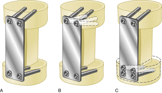
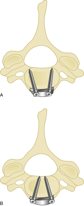
Such dynamic plates now restrict screw backout while also allowing some variability in translational and rotational movements. There are two main two kinds of dynamic anterior cervical plates manufactured by the spinal device companies, rotational and translational. In the semiconstrained rotational design, variable-angle screw systems allow the screws to toggle inside the bone. This rotational movement can also lead to instrumentation failure (Fig. 177-3). Examples include anterior cervical plates from Codman, Blackstone, Acufix, Zephir, and Atlantis (hybrid and variable). The semiconstrained translational design allows translational motion that is provided by the plate–screw interface. Examples include the ABC plate, DOC system, and Premier plate.
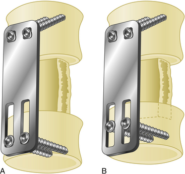
Dynamic implants allow natural subsidence to occur (Fig. 177-4) while effectively stabilizing the spine by preventing excessive movements in translation and rotation. Load sharing helps improve normal bone healing, resulting in earlier fusion. Decreased rates of construct failure have been reported with dynamic implants.13
Advantages and Disadvantages of Anterior Cervical Plates
Advantages
Anterior cervical plates have the following advantages:
• They augment stabilization, enhancing the likelihood of a solid fusion.
• They reduce the need for external bracing or halo vest placement, and they allow mobilization of the adjacent spinal segments.
• They reduce the risk of graft extrusion.
• They significantly reduce the rate of nonunion. Nonunion rates range from 11% to 63% in multilevel interbody fusion cases and from 25% to 45% in corpectomy and strut graft applications.14
If a cervical kyphosis is not severe, an anterior plate can also be used to reduce it. This is achieved by spreading the disc space with a vertebral body spreader, followed by lordotic graft and plate placement (Fig. 177-5).
Indications
Anterior cervical plates have been widely used in cases of trauma and after anterior corpectomy for cervical spondylotic myelopathy. 3,7,14,15 Anterior cervical plate placement is indicated in the following conditions:
• Cervical spine trauma with anterior column injury
• Cases of cervical spondylotic myelopathy requiring anterior decompression via ACDF
• In anterior surgery in patients who have been previously treated with a cervical laminectomy
• Following decompression and stabilization of cervical spine tumors involving the anterior column
• In post-laminectomy kyphosis following anterior decompression
In his first series, Caspar used plates only in cases of cervical trauma.6 This has given way to widespread use in cervical tumors and following decompressive surgery for cervical disc disease.7 In the case of plating following cervical corpectomy, vertebral body reconstruction can be performed using bone autograft or allograft, polymethyl methacrylate, or nonexpandable or expandable cages.
The diagnosis of cervical instability requires a subjective evaluation. White and Panjabi have developed a scoring system to easily determine spinal instability (Table 177-1).
Table 177-1 Instability Criteria of Subaxial Cervical Spine Injuries26
| Criteria | Point Value∗ |
|---|---|
| Anterior elements, nonfunctional | 2 |
| Posterior elements, nonfunctional | 2 |
| Sagittal plane translation > 3.5 mm | 2 |
| Sagittal plane angulation > 11 degrees | 2 |
| Positive stretch test | 2 |
| Spinal cord injury | 2 |
| Nerve root injury | 1 |
| Abnormal disc-space narrowing | 1 |
| Dangerous loading anticipated | 1 |
Plate Placement
Proper plate placement is very important. To enhance fusion and improve outcomes, the following general rules should be followed in to achieve better plate fixation.15
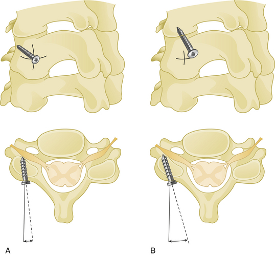
Cranial and caudal angulation (approximately 12 to 15 degrees) provides a stronger construct. Convergent screws (medially angulated screws at approximately 6 degrees in relation to midline) also provide extra strength. Although divergent screws (lateral angulation) might provide similar strength, they are not as widely accepted owing to the risk of nerve root injury (Fig. 177-6). Prebent or lordotic plates help protect against screw loosening. However, overbending of the plate should be avoided to avoid implant fatigue.
Irrigation during drilling should be used to avoid thermal injury.
Complications
Difficulty in swallowing, however, has increased in incidence with anterior cervical plate application. Esophageal perforation related to plate or screw erosion has also been reported.16,17
Wound infection does not appear to be more common with the use of plates. If, however, an osteomyelitis or wound infection develops, it may be necessary to remove the plate.
Screw loosening and backout are the most common complications of cervical plating. Traynelis has reported a 3.5% incidence of such complications.18 Minimal screw loosening is usually not clinically important, but it does require close radiologic follow-up. Significant screw backout, however, can require removal of the screw owing to the risk of perforating the esophagus.7,18 The most common causes of screw loosening are placement into the disc space or into osteoporotic bone.18
Screw breakage and plate fracture are occasional complications of anterior cervical plating.7,18,19
Posterior Stabilization Techniques
A number of posterior fixation procedures have been used for one-stage posterior decompression and stabilization of the cervical spine. In 1960 Robinson and Southwick provided details of a facet fusion of the cervical spine after laminectomy.20
Wiring Techniques
Spinous Process Wiring (Rodgers) Technique
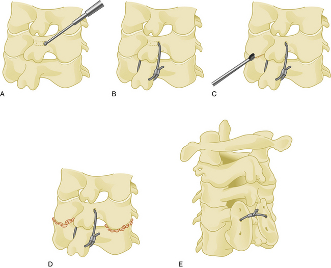
The spinous process wiring technique was first used by Rodgers in 1942 for stabilizing fracture-dislocations of the lower cervical spine.21 First, a hole is created at the junction of the spinous process and lamina using a drill or towel clamp. This is followed by passing an 18-gauge wire through the hole. Wire pullout strength is increased if this hole is closer to the base of the spinous process. The wire is then passed below the lower spinous process or through another hole created in similar fashion, making a loop or a figure-of-eight (Fig. 177-7). After lateral tightening of the wire construct, the lamina and facet joints are decorticated and bone chips are placed overlying these structures. Spinous process wires act like a posterior tension band (Fig. 177-8).
Sublaminar Wiring Technique
The risk of damage to the dura and spinal cord may be decreased by performing small laminotomies, removing the ligamentum flava, and visualizing the dura before passing the wire. Use of a wire passer or a thick silk suture can help sublaminar guidance of the wire. The wire should be bent in a concavity that approximates the laminar slope, and both ends must be controlled during passage. After passage, both ends of the wire are bent laterally to prevent compression of the spinal cord. Although they provide strong stabilization, sublaminar wires should not be used at more than one level because of high complication rates.22
Bohlman’s Triple Wiring Technique
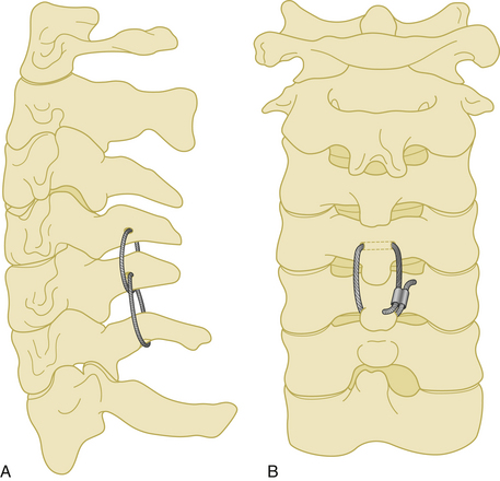
A 20-gauge wire is passed through a hole that is created at the junction of the spinous process and the lamina. The wire is then passed around the adjacent spinous process and tightened on itself (Fig. 177-9). This process is then repeated at the adjacent spinous process using a second wire, followed by a third wire that is passed through each of the two holes in the adjacent spinous processes. The lamina at each level are decorticated and bone graft is placed laterally over the decorticated lamina.
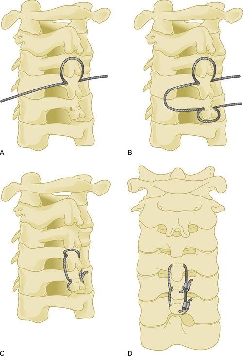
This technique was first described in 1985 by Bohlman, and it has a very high fusion rate when compared with other wiring techniques.23 Its application is easy and the risk of neural injury is low. However, as with other wiring techniques, stability in extension is minimal.
Dewar Wiring Technique
First, Steinmann pins are passed through the lamina–spinous process junctions of the most upper vertebra and the most lower vertebra to be included in the fixation. Wires passing beneath those pins, as well as bone graft placed laterally on the decorticated lamina, are then tightened in a figure-of-eight shape.
This technique was introduced by Dewar in 1992.24 Although not widely used, it is biomechanically superior to the Rodger′s technique.24
Facet–Spinous Process Wiring Technique
Posterior cervical fixation may be achieved by unilateral or bilateral wiring between the facet joint and the spinous process. The facet joint is first opened by the aid of a curette, and a dissector is placed inside the joint. A hole is then created with a drill through the inferior facet. A wire is passed through this hole, then passed under the spinous process of the caudal vertebra. After the same procedure is performed at all desired levels, small bone grafts are placed inside the facet joints after decortication of the facet cartilages, followed by tightening of the wires (Fig. 177-10).
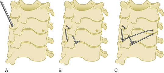
Facet wires are weaker than sublaminar and spinous process wires biomechanically.19,25,26 In addition, because the facets are very thin structures, especially in osteoporotic patients, the wires can easily cut through the facet bone. This technique is typically used in cases of laminectomy. After the facet is wired to the spinous process, the patient must wear a rigid collar after surgery.
Luque Rectangle Fixation Technique
Although it was primarily used for occipitocervical stabilization, the rectangle fixation technique may also be adapted for subaxial fixation. A rod is first shaped in a rectangle to overlie the lateral masses of the posterior cervical spine. Following the introduction of slight lordosis into the rectangular rod, sublaminar or spinous process wires are used to connect the shaped rod to the posterior elements (Fig. 177-11).
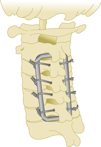
This is a very rigid and inexpensive system to create. Another advantage is that patients may be mobilized very early after surgery. However, manual shaping of the rod can be challenging.27
Laminar Hooks
One system using laminar hooks is the Halifax clamp. This is a method of posterior cervical stabilization that is attached to the adjoining laminae and tightened until no movement between the involved vertebrae is possible.28–30 This technique has lost popularity because of difficulty with application, higher rate of failure relative to other techniques, and frequent clamp dislocations.
Lateral Mass Screw Fixation
This technique was first introduced by Roy-Camille.31 Its main advantages are superiority in rotational stability, no need to preserve the posterior elements (in contrast to wiring techniques), lower risk of neural injury, and the need for little additional bone graft to effect fusion. However, there are disadvantages, such as screw loosening in cases of osteoporosis, and difficulty in correction of a kyphotic deformity.
Surgery is performed in the prone position under general anesthesia. A Mayfield head holder is used to stabilize the skull, and after a normal alignment is verified on lateral fluoroscopy, a standard posterior cervical approach is performed. The paravertebral muscles are dissected with monopolar cautery and retracted beyond the lateral edge of the lateral masses. A screw entry hole is then created in the middle of each lateral mass to be fused. In the horizontal plane, each screw is directed 10 degrees laterally in the Roy-Camille technique31 and 20 to 30 degrees laterally in other techniques to avoid vertebral artery damage. A 25-degree cranial screw trajectory was advocated by Magerl to avoid screw backout and nerve root injury32 (Fig. 177-12). Self-tapping screws that are 3.5 mm in diameter and 14 to 18 mm in length are typically used.
Connection with Plates or Rods
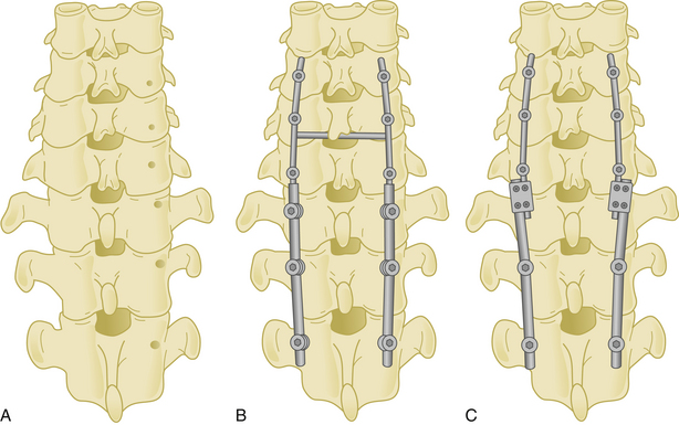
Lateral mass screws may be connected with either plates or rods (Fig. 177-13).
Lateral Mass Plates
Screw holes are prepared and tapped before placing the plate. One drawback of lateral mass plates is the constriction of the screw entry site to the holes of the plate. Some companies have developed more versatile plates with different interhole distances (e.g., 11, 13, or 15 mm); however, this is not a problem when using a screw–rod construct. Another disadvantage of lateral mass plate construction is that screws are first placed on both ends of the plate, followed by placement and tightening of the middle screws. To avoid toggling inside the hole, it is preferred to use a low speed hand drill after opening the entry hole. Bicortical purchase of the lateral mass is preferred, and this is controlled with a K-wire. To avoid injuring the underlying soft tissue, the length of the screw should ideally not exceed 16 to 18 mm.
Fusion rates with lateral mass plating is about 92%.33 Approximately a 19-degree correction of preoperative kyphotic angulation has been achieved by lateral mass plating. Studies comparing the lateral mass plate technique with posterior wiring have shown the biomechanical superiority of lateral mass screw fixation.34,35
Posterior Cervical Rods
In the case of lateral mass fracture with subluxation, screws are generally placed at least one level above and one level below the site of injury. In cases of vertebral body compression or disc rupture with anterior column instability, increased posterior construct length or anterior fusion should be considered.
Cervical Pedicle Screw Fixation
Transpedicular screws in the thoracic and lumbar spine have gained popularity because of their superior pullout strength and load-to-failure ratio. Pedicle screws in the cervical spine can also provide fixation superior to other posterior fixation methods. However, the placement of pedicle screws is challenging owing to the small size of the cervical pedicles, and it carries an inherent risk of neurovascular injury.
Cervical lateral mass screw fixation after previous laminectomy has been widely used for posterior fixation. After using pedicle fixation of C2 in hangman’s fractures,31 the same technique has been modified for use in mid- and lower cervical spine in trauma patients by Abumi and colleagues.36
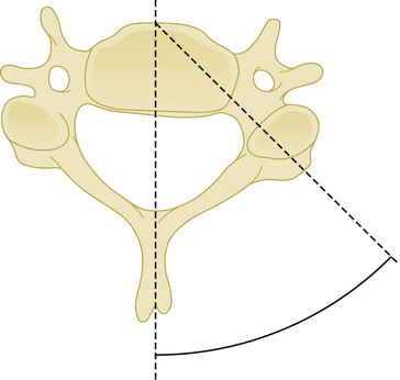
Pedicle screws placed between C3 and C7 should penetrate a point slightly lateral to the center of the articular mass and close to the inferior margin of the inferior articular process of the cranially adjacent vertebra.36 The insertion point may be penetrated with a high-speed drill. The hole is then enlarged and a small pedicle probe is inserted into the pedicle under fluoroscopic guidance. After probing the hole with a K-wire, the screw is then placed. The insertion angle of cervical pedicle screws should be 25 to 45 degrees medial (Fig. 177-14). The screw insertion angle in the sagittal plane has to be parallel to the upper endplate for C5–C7 pedicles and in a slightly cephalic direction at C2–C4.36
In a cadaveric study, Ludwig and colleagues37 showed that 12% to 18% of screws had a critical breach of the pedicle. There are many reports of increased cervical pedicle screw accuracy related to refinements in imaging techniques.38–45 However, the use of a computer-assisted image guidance system did not enhance safety or accuracy in placing pedicle screws compared with Abumi’s technique.37
Cervicothoracic Fixation
As with the other transition areas of the spine, the cervicothoracic junction presents unique problems in terms of instrumented fixation. Along these lines, various stabilization techniques have been used for anterior and posterior fixation of the cervicothoracic junction. There are many types of laminar hooks, sublaminar wires, and interspinous wires, as well as screw–rod and screw–plate combinations.46 A construct that is both safe and easy to apply is still a challenge of fixation in this region. The first reason is that this area is the transition from the mobile cervical spine to the fixed thoracic segment. Another reason is that the small size and medial angulation of the pedicles at these levels put adjacent neural structures at increased risk with pedicle violation. The incidence of misplacement of the pedicle screws in the upper thoracic spine may as high as 40%.47 Also, it is necessary to use a transitional diameter rod, or two rods of different diameters, when bridging this junction (Fig. 177-15).
Kretzer and colleagues have advocated using translaminar screws at the T1 and T2 levels to minimize the risk of adjacent neural injury,46 and they claim that this technique is also technically easier, because the entire lamina can be visualized and used to guide screw insertion.
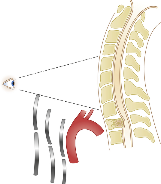
Anterior approaches to the cervicothoracic region are obstructed by the sternum, clavicle, and great vessels (Fig. 177-16). A standard cervical anterolateral approach may be sufficient to reach the first two thoracic vertebrae. However, a manubriotomy or manubrioclaviculotomy may be necessary to provide better anterior access to this region (Fig. 177-17).
Abumi K., Itoh H., Taneichi H., et al. Transpedicular screw fixation for traumatic lesions of the middle and lower cervical spine: description of the techniques and preliminary report. J Spin Disord. 1994;7:19-28.
Caspar W. Anterior stabilization with the trapezoidal osteosynthetic plate technique in cervical spine injuries. In: Kehr P., Weidner A. cervical Spine I. New York: Springer-Verlag; 1987:198-204.
Cloward R.B. The anterior approach for the removal of ruptured cervical disks. J Neurosurg. 1958;15:602-617.
Smith G.W., Robinson R.A. The treatment of cervical spine disorders by anterior removal of the intervertebral disc and interbody fusion. J Bone Joint Surg Am. 1958;40:607-624.
1. Smith G.W., Robinson R.A. The treatment of cervical spine disorders by anterior removal of the intervertebral disc and interbody fusion. J Bone Joint Surg Am. 1958;40:607-624.
2. Cloward R.B. The anterior approach for the removal of ruptured cervical disks. J Neurosurg. 1958;15:602-617.
3. Herman J.M., Sonntag V.K.H. Cervical corpectomy and plate fixation for postlaminectomy kyphosis. J Neurosurg. 1994;80:963-970.
4. Böhler J., Gaudernak T. Anterior plate stabilization for fracture-dislocations of the lower cervical spine. J Trauma. 1980;20(3):203-205.
5. Orozco Delclos R., Llovet Tapies J. Osteosintesis en las fractures de raquis cervical. Revista Ortop Traumatol. 1970;14:285-288.
6. Caspar W. Anterior stabilization with the trapezoidal osteosynthetic plate technique in cervical spine injuries. In: Kehr P., Weidner A. cervical Spine I. New York: Springer-Verlag; 1987:198-204.
7. Caspar W., Barbier D.D., Klara P.M. Anterior cervical fusion and Caspar plate stabilization for cervical trauma. Neurosurgery. 1989;25:491-502.
8. Tippets R.H., Apfelbaum R.I. Anterior cervical fusion with the Caspar instrumentation system. Neurosurgery. 1988;22:1008-1013.
9. Rengachary S.S., Duke D.A. Stabilization of the cervical spine with the locking plate system. In: Hitchon P.W., Traynelis V.C., Rengachary S.S. techniques in Spinal Fusion and Stabilization. New York: Thieme Medical Publishers; 1995:176-190.
10. Suh P.B., Kostuik J.P., Esses S.I. Anterior cervical plate fixation with the titanium hollow screw plate system. A preliminary report. Spine. 1990;15:1070-1081.
11. Harkey H.L. Synthes cervical spine locking plate (Mosher plate). Neurosurgery. 1993;32:682-683.
12. Lowery G.L. Anterior cervical osteosynthesis: orion anterior cervical plate system. In: Hitchon P.W., Traynelis V.C., Rengachary S.S. techniques in Spinal Fusion and Stabilization. New York: Thieme Medical Publishers; 1995:191-197.
13. Steinmetz M.P., Benzel E.C., Apfelbaum R.I. Axially dynamic implants for stabilization of the cervical spine. Neurosurgery. 2006;59(4 Suppl 2):ONS378-ONS388.
14. An H.S., Gordin R., Renner K. Anatomic considerations for plate-screw fixation of the cervical spine. Spine (Suppl). 1991;16:S548-S551.
15. Baskin J.J., Sawin P.D., Hartl R., et al. Surgical techniques for stabilization of the subaxial cervical spine (C3-C7), Schmidek H.H., Sweet W.H., editors, operative Neurosurgical Techniques, Philadelphia, WB Saunders, 2005;vol 2:1915-1943.
16. Hancı M., Toprak M., Sarıoğlu AÇ, et al. Oesophageal perforation subsequent to anterior cervical spine screw/plate fixation. Paraplegia. 1995;33:606-609.
17. Cagli S., Isik H.S., Zileli M. Cervical screw missing secondary to delayed esophageal fistula: case report. Turk Neurosurg. 2009;19(4):437-440.
18. Traynelis V.C. Anterior and posterior plate stabilization of the cervical spine. Neurosurg Q. 1992;2:59-76.
19. Ulrich C., Woersdoerfer O., Kalff R., et al. Biomechanics of fixation systems to the cervical spine. Spine (Suppl). 1991;16:S4-S9.
20. Robinson R.A., Southwick W.O. Indications and techniques for early stabilization of the neck in some fracture dislocations of cervical spine. South Med J. 1960;53:565-579.
21. Rodgers W.A. Treatment of fractures and dislocations of the cervical spine. J Bone Joint Surg Am. 1942;24:245-258.
22. Boerre N.R., Dove J. The selection of wires for sublaminar fixation. Spine. 1993;18:497-503.
23. McAfee P.C., Bohlman H.H., Wilson W.L. Triple wire fixation technique for stabilization of acute fracture, dislocations of the cervical spine: a biomechanical analysis. Orthop Trans. 1985;9:142-150.
24. Bernstein A.J., Simmons G.H., Capicotto W.N., et al. The Dewar posterior cervical fusion: description and comparative results. Orthop Trans. 1992;16:151-159.
25. White A.A., Johnson R.M., Panjabi M.M., et al. Biomechanical analysis of clinical stability in the cervical spine. Clin Orthop Relat Res. 1975;109:85-96.
26. White A.A., Panjabi M.M. Clinical Biomechanics of the Spine. Philadelphia: JB Lippincott; 1978.
27. MacKenzie A.I., Uttley D., Marsh H.T., et al. Craniocervical stabilization using Luque/Hartshill rectangles. Neurosurgery. 1990;26:32-36.
28. Aldrich E.F., Weber P.B., Crow W.N. Halifax interlaminar clamp for posterior cervical fusion: a long-term follow-up review. J Neurosurg. 1993;78:702-708.
39. Maniker A.H., Schulder M., Duran H.L. Halifax clamps: efficacy and complications in posterior cervical stabilization. Surg Neurol. 1995;43(2):140-146.
30. Seex K., Johnston R.A. Interlaminar clamp for posterior fusions (letter). J Neurosurg. 1991;75:495-496.
31. Roy-Camille R., Salient G., Mazel C. Internal fixation of the unstable cervical spine by a posterior osteosynthesis with plate and screws. In: Cervical Spine Research Society the Cervical Spine, 2nd ed. Philadelphia: JB Lippincott; 1989:390-393.
32. Errico T., Uhl R., Cooper P., et al. Pullout strength comparison of two methods of orienting screw insertion in the lateral masses of the bovine cervical spine. J Spinal Disord. 1992;5:459-463.
33. Fehlings M.G., Cooper P.R., Errico T.J. Posterior plates in the management of cervical spinal in instability: long-term results in 44 patients. J Neurosurg. 1994;81:341-349.
34. Gill K., Paschal S., Corin J., et al. Posterior plating of the cervical spine: a biomechanical comparison of different posterior fusion techniques. Spine. 1988;13:813-816.
35. Montesano P.X., Juach E.C., Anderson P.A., et al. Biomechanics of cervical spine internal fixation. Spine. 1991;16(Suppl 3):S10-S16.
36. Abumi K., Itoh H., Taneichi H., et al. Transpedicular screw fixation for traumatic lesions of the middle and lower cervical spine: description of the techniques and preliminary report. J Spin Disord. 1994;7:19-28.
37. Ludwig S.C., Kowalski J.M., Edwards C.C., Heller J.G. Cervical pedicle screws: comparative accuracy of two insertion techniques. Spine. 2000;25:2675-2681.
38. Abumi K., Kaneda K., Shono Y., Fujiya M. One-stage posterior decompression and reconstruction of the cervical spine by using pedicle screw fixation systems. J Neurosurg (Spine 1). 1999;90:19-26.
39. Kantelhardt S.R., Larsen J., Bockermann V., et al. Intraosseous ultrasonography to determine the accuracy of drill hole positioning prior to the placement of pedicle screws: an experimental study. J Neurosurg Spine. 2009;11(6):673-680.
40. Koller H., Hitzl W., Acosta F., et al. In vitro study of accuracy of cervical pedicle screw insertion using an electronic conductivity device (ATPS part III). Eur Spine J. 2009;18(9):1300-1313.
41. Lu S., Xu Y.Q., Lu W.W., et al. A novel patient-specific navigational template for cervical pedicle screw placement. Spine 15. 2009;34(26):E959-E966.
42. Miyamoto H., Uno K. Cervical pedicle screw insertion using a computed tomography cutout technique. J Neurosurg Spine. 2009;11(6):681-687.
43. Onibokun A., Khoo L.T., Bistazzoni S., et al. Anatomical considerations for cervical pedicle screw insertion: the use of multiplanar computerized tomography measurements in 122 consecutive clinical cases. Spine J. 2009;9(9):729-734.
44. Ryken T.C., Owen B.D., Christensen G.E., Reinhardt J.M. Image-based drill templates for cervical pedicle screw placement. J Neurosurg Spine. 2009;10(1):21-26.
45. Yukawa Y., Kato F., Ito K., et al. Placement and complications of cervical pedicle screws in 144 cervical trauma patients using pedicle axis view techniques by fluoroscope. Eur Spine J. 2009;18(9):1293-1299.
46. Kretzer R.M., Sciubba D.M., Bagley C.A., et al. Translaminar screw fixation in the upper thoracic spine. J Neurosurg Spine. 2006;5:527-533.
47. Vougioukas V.I., Weber J., Scheufler K.M. Clinical and radiological results after parapedicular screw fixation of the thoracic spine. J Neurosurg Spine. 2005;3:283-287.
[/level-membership-for-neurosurgery-category][not-level-membership-for-neurosurgery-category]
Chapter 177 Stabilization of the Subaxial Cervical Spine (C3–C7)
Fusions by anterior approaches have been widely used in cervical spine injuries, allowing anterior decompression of the spinal column. Anterior fusion techniques were first introduced in 1955 by Smith and Robinson1 and then popularized by Cloward.2
The first application of a metal plate as a supplement to an anterior bone graft in cases of cervical dislocation was performed in 1975 by Herrmann.3 In 1980, Böhler4 also used small plates as proposed by Orozco and Llovet.5 In 1980 Caspar subsequently popularized the use of anterior cervical plates, resulting in more widespread use of Caspar plating6,7 in the mid-1980s in both Europe and the United States.8
Anterior Stabilization Techniques
Anterior cervical plates have significantly changed since their early application in cervical trauma. They are now commonplace in anterior cervical decompression and fusion (ACDF) procedures, especially in cases requiring decompression of two or more levels. Routine use for the treatment of cervical spondylosis has caused plate design to change significantly in recent years. The first anterior cervical plates were unlocked and required bicortical purchase. Anterior cervical plates with constrained designs and locking plate–screw head connections then came into favor.9 The latest plates are semiconstrained dynamic plates that allow some movement in rotation and translation (Fig. 177-1).
Biomechanics of Cervical Plates
Screw choice and insertion technique also affect the biomechanical properties of anterior plating. For instance, hollow screws with small holes on the shaft were developed to allow improved osteointegration at the screw–bone interface.10 They were removed from the market because of high screw fracture rates and increased difficulty of removal.
Medial or lateral angulation of anterior screws during insertion results in a triangulation in the axial plane, whereas cranial and caudal angulation results in sagittal plane triangulation. Varying the angle of trajectory provides improved construct strength and lessens the risk that the screw will back out (Fig. 177-2).
Although anterior cervical plates have undergone many improvements since their introduction, several questions still remain regarding the clinical application of this technique. Such questions include the following: Which plate should be used, constrained or nonconstrained? Should screws be placed in a unicortical or bicortical fashion? Should a screw be placed into the interbody bone graft? In the case of cervical corpectomy, should intermediate points of fixation should be added to improve construct stability?
Types of Plates
Static Plates
Second-generation plates are constrained plates (static plates). Constrained plates provide strong fixation between the plate surface and the screw heads. Examples include Synthes cervical spine locking plates (CSLPs), Orion plates, and Atlantis plates. These plates employ a fixed moment arm cantilever beam design. Screw backout is restricted in these models.11,12 The CSLP is an example of a second-generation anterior cervical plate and was first introduced by Morscher with fixed-angle screws. Small set screws are placed into the main screw heads, widening the screw head and locking the head to the plate. The CSLP variable-angle plate is a modification that allows up to 20 degrees of variability in the plate–screw angle. Other anterior cervical locking plates in this category use a special screw head design that expands when it incorporates into the plate.
Dynamic Plates
Third-generation plates are semiconstrained plates (dynamic) plates. These plates have designs that allow a variable amount of graft subsidence. Subsidence is observed during aging and after spine surgery and is accepted as a naturally occurring process. Although anterior cervical plates help to stabilize the spine, they also constrict subsidence. For that reason, an anterior plate that carries most of the axial load instead of sharing it with the bone graft has a high rate of failure.13 Dynamic plates were developed to avoid the late complications of rigid plates.
Screw loosening and screw and plate fracture are more common in cases of multilevel fusion with either a corpectomy or ACDF grafts.3 The main reason is graft absorbtion resulting in subsidence. Although it is a gradual process, if the loss of graft height cannot be accommodated by the plate–screw angle, the screw has increased risk of fracture.
Such dynamic plates now restrict screw backout while also allowing some variability in translational and rotational movements. There are two main two kinds of dynamic anterior cervical plates manufactured by the spinal device companies, rotational and translational. In the semiconstrained rotational design, variable-angle screw systems allow the screws to toggle inside the bone. This rotational movement can also lead to instrumentation failure (Fig. 177-3). Examples include anterior cervical plates from Codman, Blackstone, Acufix, Zephir, and Atlantis (hybrid and variable). The semiconstrained translational design allows translational motion that is provided by the plate–screw interface. Examples include the ABC plate, DOC system, and Premier plate.
Dynamic implants allow natural subsidence to occur (Fig. 177-4) while effectively stabilizing the spine by preventing excessive movements in translation and rotation. Load sharing helps improve normal bone healing, resulting in earlier fusion. Decreased rates of construct failure have been reported with dynamic implants.13
Advantages and Disadvantages of Anterior Cervical Plates
Advantages
Anterior cervical plates have the following advantages:
• They augment stabilization, enhancing the likelihood of a solid fusion.
• They reduce the need for external bracing or halo vest placement, and they allow mobilization of the adjacent spinal segments.
• They reduce the risk of graft extrusion.
• They significantly reduce the rate of nonunion. Nonunion rates range from 11% to 63% in multilevel interbody fusion cases and from 25% to 45% in corpectomy and strut graft applications.14
If a cervical kyphosis is not severe, an anterior plate can also be used to reduce it. This is achieved by spreading the disc space with a vertebral body spreader, followed by lordotic graft and plate placement (Fig. 177-5).
Indications
Anterior cervical plates have been widely used in cases of trauma and after anterior corpectomy for cervical spondylotic myelopathy. 3,7,14,15 Anterior cervical plate placement is indicated in the following conditions:
• Cervical spine trauma with anterior column injury
• Cases of cervical spondylotic myelopathy requiring anterior decompression via ACDF
• In anterior surgery in patients who have been previously treated with a cervical laminectomy
• Following decompression and stabilization of cervical spine tumors involving the anterior column
• In post-laminectomy kyphosis following anterior decompression
In his first series, Caspar used plates only in cases of cervical trauma.6 This has given way to widespread use in cervical tumors and following decompressive surgery for cervical disc disease.7 In the case of plating following cervical corpectomy, vertebral body reconstruction can be performed using bone autograft or allograft, polymethyl methacrylate, or nonexpandable or expandable cages.
The diagnosis of cervical instability requires a subjective evaluation. White and Panjabi have developed a scoring system to easily determine spinal instability (Table 177-1).
Table 177-1 Instability Criteria of Subaxial Cervical Spine Injuries26
| Criteria | Point Value∗ |
|---|---|
| Anterior elements, nonfunctional | 2 |
| Posterior elements, nonfunctional | 2 |
| Sagittal plane translation > 3.5 mm | 2 |
| Sagittal plane angulation > 11 degrees | 2 |
| Positive stretch test | 2 |
| Spinal cord injury | 2 |
| Nerve root injury | 1 |
| Abnormal disc-space narrowing | 1 |
| Dangerous loading anticipated | 1 |
Plate Placement
Proper plate placement is very important. To enhance fusion and improve outcomes, the following general rules should be followed in to achieve better plate fixation.15
[/not-level-membership-for-neurosurgery-category]
