[level-membership-for-neurosurgery-category]
Chapter 90 Spinal Deformity
Measuring, Defining, and Classifying
The spine is composed of regions with distinct alignment and biomechanical properties that contribute to global alignment. Although regional spinal curves vary widely from the occiput to the pelvis in asymptomatic individuals, global spinal alignment is maintained in a much narrower range for maintenance of horizontal gaze and balance of the spine over the pelvis and femoral heads. Spinal deformity is defined as a deviation from normal spinal alignment.1,2 Because the human condition is in part defined by the ability to comfortably stand upright and because the treatment of many patients with spinal disorders is directed at restoring this condition, spinal deformity needs to be defined in relation to neutral upright spinal alignment (NUSA) in asymptomatic individuals. NUSA in asymptomatic individuals is defined as standing with the knees and hips comfortably extended, the shoulders neutral or flexed, the neck neutral, and the gaze horizontal. Analysis of spinal alignment involves both clinical and radiographic evaluation. Although there are a myriad of angles and displacements for measuring spinal alignment, our subsequent analysis offers a systematic approach to analyzing regional and global spinal alignment.
Clinical and Radiographic Evaluation of Deformity
To evaluate a spinal deformity, it is necessary to do the following:
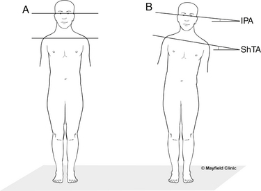
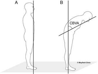
1. Perform clinical measurements (facilitated with photographs) in a neutral upright position (standing with the knees and hips comfortably extended, the shoulders and neck neutral) and a forward bend position (standing with feet together, the knees comfortably extended, the hips and spine flexed, and the arms dependent with fingers and palms opposed).
2. Measure occipitocervical and cervical angles and displacements on standard standing anteroposterior and lateral cervical spine radiographs in a neutral upright position (standing with the knees and hips comfortably extended, the shoulders and neck neutral).
3. Measure thoracic, lumbar, sacral, and pelvic angles and displacements, including spinal balance, on standard standing anteroposterior and lateral long cassette radiographs in a neutral upright standing position (standing with the knees and hips comfortably extended, the shoulders neutral or flexed [flexed for lateral radiographs], and the neck neutral).
4. Obtain side-bending (supine) and flexion-extension (standing) radiographs when appropriate for evaluating the flexibility of a deformity curve.
Coronal Alignment Angles and Displacements
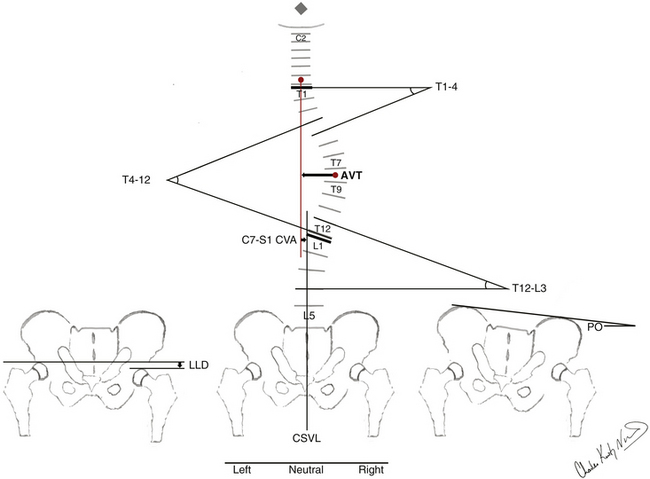
By convention, coronal angles have a positive value. Scoliotic curves are named for the convexity to the right or left. Coronal angulation of the head, shoulders, or pelvis is named for the elevated side: right is right up and left is left up. Schematic illustrations of representative clinical and radiographic measuring techniques for the coronal spinal alignment angles and displacements are detailed in Figures 90-1 and 90-2.
Regional Spinal Alignment
Occipitocervical (O-C2) curves are defined as having an apex from the occiput to C2; a coronal occipital reference line and the caudal end vertebrae are defined for measuring the Cobb angle.3
Cervical coronal curves are defined as having an apex from the C2-3 disc to the C6-7 disc and measured by the Cobb method from the end vertebrae.3
The cervicothoracic junction angles are defined from C7 to T1. Cervicothoracic coronal curves are defined as having an apex from C7 to T1 and measured by the Cobb method from the end vertebrae.3
Proximal thoracic (T1-2 disc to T5 disc), main thoracic (T5-6 disc to T11-12 disc), thoracolumbar (T12-L1), lumbar (L1-2 disc to L4-5 disc), and lumbosacral (L5-S1) coronal curves are defined as having an apex in the above regions or zones and measured by the Cobb method from the end vertebrae.3
The end vertebrae for all coronal curves are defined as the most rostral and caudal vertebrae that maximally tilt into the concavity of the curve. The end vertebrae define the ends of the scoliotic curve. The rostral end vertebra is the first vertebra in the rostral direction from a curve apex whose superior surface is tilted maximally toward the concavity of the curve. The caudal end vertebra is the first vertebra in the caudal direction from a curve apex whose caudal surface is tilted maximally toward the concavity of the curve. The apical vertebra or disc of a curve is defined as the most horizontal and laterally deviated vertebra or disc of the curve.4 Apical vertebral translation is defined as the horizontal distance measured from the C7 plumb line to the center of the apical vertebral body or disc for proximal thoracic and main thoracic curves and from the central sacral vertical line (CSVL) to the center of the apical vertebral body or disc for thoracolumbar and lumbar curves.4 The CSVL is defined as a vertical reference line drawn through the center of the S1 end plate. Apical vertebral rotation (AVR) is defined by the Nash-Moe classification system.4,5 (Because AVR is defined on anteroposterior radiographs, AVR is included with the coronal alignment.) Lateral olisthesis is defined by a modified Meyerding classification system.4,6 For lumbosacral coronal curves, the apical vertebra or disc is defined from L5 to S1; the rostral end vertebra and a horizontal reference line are defined for measuring the Cobb angle (on supine side-bending radiographs, the horizontal reference line may be reconstructed from the standing radiographs).
Sagittal Alignment Angles and Displacements
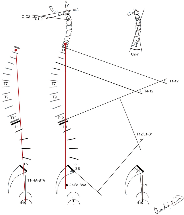
By convention, kyphosis has a positive value and lordosis a negative value. Schematic illustrations of representative clinical and radiographic measuring techniques for the sagittal and coronal spinal alignment angles and displacements are detailed in Figures 90-3 and 90-4.
Regional Spinal Alignment
Occipitocervical junction angles are defined from the occiput to C2. The occiput-C2 angle is defined as the angle subtended by the McGregor line and a line drawn parallel to the inferior end plate of C2. The McGregor line is drawn from the dorsal rostral aspect of the hard palate to the most caudal point on the midline of the occipital curve.7 The C1-2 angle is defined as the angle subtended by a line drawn parallel to the inferior aspect of C1 and a line drawn parallel to the inferior end plate of C2.
Cervicothoracic junction angles are defined from C6 to T2, as measured using the Cobb method.3 The C6-T2 angle is measured from the superior end plate of C6 to the inferior end plate of T2.
Thoracic kyphosis angles are defined from T1 to T12, as measured using the Cobb method.3 Total thoracic kyphosis is measured from the superior end plate of T1 to the inferior end plate of T12. The proximal thoracic kyphosis is measured from the superior end plate of T1 to the inferior end plate of T5. The main thoracic kyphosis is measured from the superior end plate of T4 to the inferior end plate of T12.
Thoracolumbar junction angles are defined from T10 to L2, as measured using the Cobb method.3 The T10-L2 angle is measured from the superior end plate of T10 to the inferior end plate of L2.
Lumbosacral lordosis angles are defined from T12-L1 to S1, as measured using the Cobb method.3 Total lumbosacral lordosis is measured from either the caudal end plate of T12 or the rostral end plate of L1 to the rostral end plate of S1. Lumbar lordosis is measured from the rostral end plate of L1 to the caudal end plate of L5.
Lumbosacral junctional angles are measured from L4 to S1, using the Cobb method.3 The L4-S1 angle is measured from the rostral end plate of L4 to the superior end plate of S1. The L4-5 angle is measured from the rostral end plate of L4 to the rostral end plate of L5. The L5-S1 angle is measured from the superior end plate of L5 to the rostral end plate of S1.
Ventral and dorsal olisthesis are defined by a modified Meyerding classification system.4,6
Pelvic Alignment
Pelvic morphology and rotation are defined by the pelvic incidence, pelvic tilt, and sacral slope. Pelvic incidence (PI) is a constant value unaffected by body posture. The PI is defined as an angle subtended by a line drawn from the hip axis to the midpoint of the sacral end plate and a line perpendicular to the center of the sacral end plate.8 The hip axis (HA) is defined as the midpoint between the approximate centers of both femoral heads. As PI increases, lumbosacral lordosis must increase to maintain balanced sagittal global spinal alignment. In contrast to the PI, the sacral slope (SS) and pelvic tilt (PT) are posturally dependent values and change with rotation of the pelvis on the hip axis. SS is defined as the angle subtended by a horizontal reference line and the sacral end plate. PT is defined as the angle subtended by a vertical reference line through the HA and a line drawn from the midpoint of the sacral end plate to the HA. PT has a positive value when the midpoint of the sacrum is dorsal to the vertical reference line and a negative value when the midpoint of the sacrum is ventral to the vertical reference line. Geometrically, these pelvic angles produce the following equation: PI = SS + PT.8 The pelvis rotates on the HA to help maintain balanced sagittal global spinal alignment.
Defining Spinal Deformity
Deformity is defined as a deviation from the normal shape or size.1,2 The eight critically important characteristics of a spinal deformity include patient age; spinal abnormality, including neurologic compromise (e.g., radiculopathy, myelopathy); deformity curve location, pattern, magnitude, and flexibility; pelvic alignment; and global spinal alignment. Spinal deformity may be the primary or a secondary spinal disorder. The deformity may be idiopathic or secondary to known spinal abnormality (e.g., neuromuscular, degenerative, osteoporotic, infectious, traumatic). Spinal deformity may occur in a single plane or in a combination of three planes: coronal, sagittal, and axial. The three basic types of spinal deformity include scoliosis, kyphosis, and lordosis. Each may occur singly or in combination. In combination, coronal and sagittal deformity produces scoliokyphosis and scoliolordosis. Because the human condition is in part defined by the ability to comfortably stand upright and because treatment of many patients with spinal disorders is directed at restoring this condition, spinal deformity needs to be defined in relation to NUSA from the occiput to the pelvis in asymptomatic individuals.
Classification Systems for Thoracic-Lumbar Spinal Deformity
King et al., in 1983, established the first formal classification system for adolescent idiopathic scoliosis that gained widespread use among spinal surgeons (Table 90-1).9 Of the eight critically important characteristics of a spinal deformity, the King classification system is limited to adolescent idiopathic scoliosis and only evaluates scoliotic curves in the coronal plane. The classification system focuses on thoracic curves and combined thoracic-lumbar double curves. Scoliotic deformity curve location, pattern, magnitude, and flexibility are included. Pelvic alignment and global spinal alignment are not included. A significant force in the development of this initial spinal deformity classification was the intention to define levels of fusion.9 This systematic approach served as a baseline from which to begin a more scientific understanding of deformity. The widespread application of the King classification system eventually led specialists to recognize its shortcomings. Classification information was based only on coronal images. The neglect of sagittal and axial alignment resulted in correction of spinal deformity in the coronal plane, often ignoring the sagittal and axial plane and producing sagittal deformity, namely the flatback syndrome. At the time of the King classification system development, Harrington rods were the primary instrumentation device and had limited ability to correct or control sagittal curves. Newer three-dimensional segmental instrumentation techniques, including hooks and pedicle screws, came to highlight the three-dimensional aspect of spinal deformity correction that was not fully addressed by the King classification. The King classification has poor applicability to three-dimensional correction of spinal deformity.10
TABLE 90-1 King Classification of Adolescent Idiopathic Scoliosis
| Group | Criteria |
|---|---|
| Type I | S-shaped curve in which both thoracic curve and lumbar curve cross midline Lumbar curve larger than thoracic curve on standing radiograph Flexibility index a negative value (thoracic curve greater than or equal to lumbar curve on standing radiograph, but moreflexible on side-bending view) |
| Type II | S-shaped curve in which thoracic curve and lumbar curve cross midline Thoracic curve greater than or equal to lumbar curve Flexibility index ≥0 |
| Type III | Thoracic curve in which lumbar curve does not cross midline (so-called overhang) |
| Type IV | Long thoracic curve in which L5 is centered over sacrum but L4 tilts into long thoracic curve |
| Type V | Double thoracic curve with T1 tilted into convexity of upper curve Upper curve structural on side-bending view |
From King HA, Moe JH, Bradford DS, et al: The selection of fusion levels in thoracic idiopathic scoliosis. J Bone Joint Surg [Am] 65:1302–1313, 1983.
Coonrad, in 2000, and Qiu, in 2005, built on the King classification system to develop two new classification systems.11,12 Of the eight critically important characteristics of a spinal deformity, the Coonrad classification system and Qiu Peking Union Medical College method are limited to idiopathic scoliosis and evaluate scoliotic curves predominantly in the coronal plane. The classification systems include thoracic curves and combined thoracic-lumbar double curves as well as thoracolumbar and lumbar curves. Scoliotic deformity curve location, pattern, magnitude, and flexibility are included. Pelvic alignment and global spinal alignment are not included. The inclusion of thoracolumbar and lumbar scoliotic deformity curve patterns offers an improvement over the King classification system. However, in classification, the continued reliance on coronal alignment with neglect of sagittal alignment remains a significant limitation.
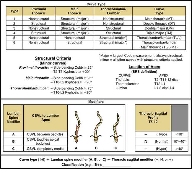
Lenke et al., in 2001, established a new system of classification for adolescent idiopathic scoliosis that included the strengths of the King system and addressed many of its shortcomings (Fig. 90-5).13 Of the eight critically important characteristics of a spinal deformity, the Lenke classification system is limited to adolescent idiopathic scoliosis. Thoracic and thoracolumbar curves are evaluated in the coronal and sagittal planes, whereas lumbar curves are evaluated in only the coronal plane. Scoliotic deformity curve location, pattern, magnitude, and flexibility are all incorporated. Pelvic alignment and global spinal alignment are not included. The Lenke classification has quickly been adopted for widespread use in treating adolescent idiopathic scoliosis, largely due to the successful accomplishment of its intended goals13:
• Comprehensive classification system for adolescent idiopathic scoliosis, including the vast majority of adolescent idiopathic scoliotic deformity curve patterns
• Analysis in both coronal and sagittal planes
• Guide for operative management and selection of appropriate levels for fusion
• Objectivity with good interobserver and intraobserver reliability14–16
• System that is relatively practical and easy to understand
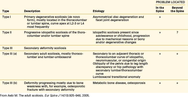
Aebi published an adult scoliosis classification system in 2005 distinguished by classification based on etiology and spinal abnormality (Table 90-2).17 Of the eight critically important characteristics of a spinal deformity, the Aebi classification system is limited to adult scoliosis. Deformity curve location, pattern, and magnitude are included for descriptive purposes only. Curve flexibility, pelvic alignment, and global spinal alignment are not incorporated. Due to its etiologic foundation, the Aebi classification is uniquely helpful in understanding the natural history of adult deformity of varying etiologies. The Aebi classification provides an alternate insight into adult/geriatric spinal deformity but is lacking in guiding comprehensive classification and treatment.
Schwab et al. presented a classification of adult deformity in 2006 (Table 90-3).18 Of the eight critically important characteristics of a spinal deformity, the Schwab classification system is limited to adult scoliotic deformity. Thoracic, thoracolumbar, and lumbar curves are evaluated in only the coronal plane, whereas lumbar curves are evaluated in the coronal and sagittal planes. Scoliotic deformity curve location, pattern, and magnitude are included. Spinal abnormality, deformity curve flexibility, pelvic alignment, and global spinal alignment are not incorporated. Classification of the degenerative process is included with a subluxation modifier. Prior established radiographic features with significant patient-reported clinical impact were used as the foundation for this classification.
TABLE 90-3 Schwab Classification of Adult Scoliosis
| Classification | Radiographic Criteria |
|---|---|
| Type | |
| I | Thoracic-only curve (no other curves) |
| II | Upper thoracic major, apex T4-8 |
| III | Lower thoracic major, apex T9-10 |
| IV | Thoracolumbar major curve, apex T11-L1 |
| V | Lumbar major curve, apex L2-4 |
| Lumbar Lordosis Modifier | |
| A | Marked lordosis (>40°) |
| B | Moderate lordosis (0°–40°) |
| C | No lordosis present (Cobb >0°) |
| Subluxation Modifier | |
| 0 | No intervertebral subluxation, any level |
| + | Maximal measured subluxation, 1–6 mm |
| ++ | Maximal subluxation >7 mm |
From Schwab F, Farcy JP, Bridwell K, et al: A clinical impact classification of scoliosis in the adult. Spine (Phila Pa 1976) 31(18):2109–2114, 2006.
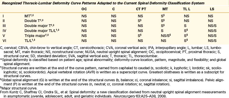
The Scoliosis Research Society (SRS) classification system for adult spinal deformity, published by Lowe et al. in 2006, is built on the King and Lenke classification systems to include the strengths of the previous classification systems and address the shortcomings (Table 90-4).19 Of the eight critically important characteristics of a spinal deformity, the classification system is limited to adult spinal deformity. Thoracic, thoracolumbar, and lumbar curves are evaluated in the coronal and sagittal planes. Deformity curve location, pattern, and magnitude as well as global spinal alignment are included. Spinal abnormality, deformity curve flexibility, and pelvic alignment are not incorporated. Classification of the degenerative process in the lumbar spine is included. The SRS classification system has made a significant advance in the classification of adult spinal deformity by including coronal and sagittal plane deformity as well as global spinal alignment. The complexity of the classification system with the exclusion of the evaluation of spinal abnormality, deformity curve flexibility, and pelvic alignment can make this system difficult for the spinal surgeon to use.
TABLE 90-4 Scoliosis Research Society Classification of Adult Spinal Deformity
| Primary Curve Types |
| Single thoracic: ST |
| Double thoracic: DT |
| Double major: DM |
| Triple major: TM |
| Thoracolumbar: TL |
| Lumbar “de novo”/idiopathic: L |
| Primary sagittal plane (SP) deformity |
| Adult Spinal Deformity Modifiers |
| Regional sagittal modifier (include only if outside normal ranges as listed) |
| PT—proximal thoracic (T2-5): ≥ +20° |
| MT—main thoracic (T5-12): ≥ +50° |
| TL—thoracolumbar (T10-L2): ≥ +20° |
| L—lumbar (T12-S1): ≥ −40° |
| Lumbar Degenerative Modifier (include only if present) |
| DDD—↓disc height and facet arthropathy based on radiography; include lowest involved level between L1 and S1 |
| LIS—listhesis (rotational, lateral antero, retro) ≥3 mm; include lowest level between L1 and L5 |
| JCT—junctional L5-S1 curve ≥10° (intersection angle superior end plates L5 and S1) |
| Global Balance Modifier (include only if imbalance present) |
| SB—sagittal C7 plumb ≥5 cm anterior or posterior to sacral promontory |
| CB—coronal C7 plumb ≥3 cm right or left of CSVL |
| Definition of Regions |
| Thoracic apex: T2–T11-T12 disc |
| Thoracolumbar apex: T12-L1 |
| Lumbar apex: L1-2 disc to L4 |
| Criteria for Specific Major Curve Types |
| Thoracic curves |
| Curve ≥40° |
| Apical vertebral body lateral to C7 plumbline |
| T1 rib or clavicle angle ≥10° upper thoracic curves |
| Thoracolumbar and lumbar curves |
| Curve ≥30° |
| Apical vertebral body lateral to CSVL |
| Primary sagittal plane deformity |
| No major coronal curve |
| One or more regional sagittal measurements (PT, MT, TL, L) outside normal range |
CSVL, central sacral vertical line.
From Lowe T, Berven SH, Schwab FJ, et al: The SRS classification for adult spinal deformity: building on the King/Moe and Lenke classification systems. Spine (Phila Pa 1976) 31:S119–S125, 2006.
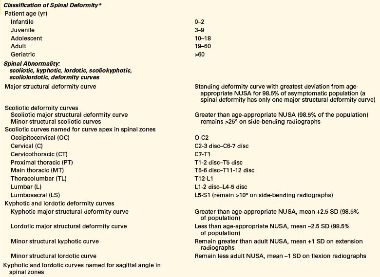
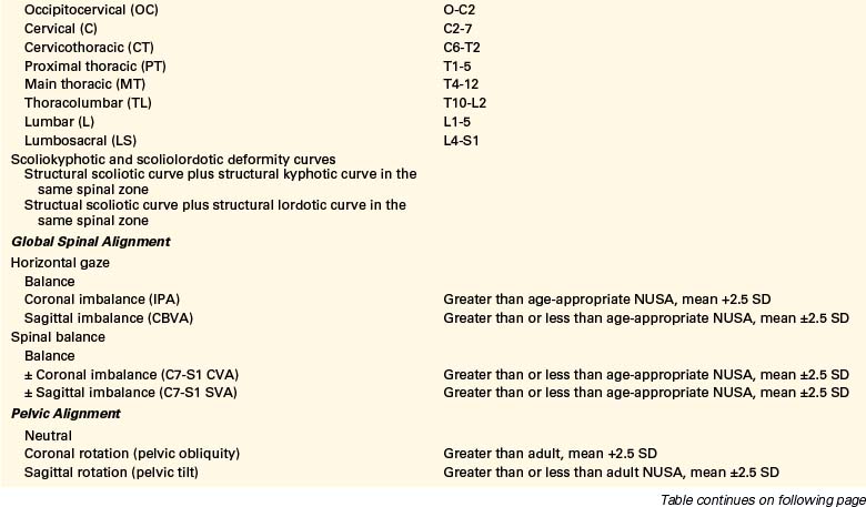
A comprehensive classification of spinal deformity, published by Kuntz and colleagues in 2009, was derived from neutral upright spinal measurements in asymptomatic individuals.20,21 The premise of the CKIV classification system is that because the human condition is in part defined by the ability to comfortably stand upright and because treatment of many patients with spinal disorders is directed at restoring this condition, spinal deformity in this classification is defined in relation to the NUSA from the occiput to the pelvis in asymptomatic individuals (Tables 90-5 and 90-6). Of the eight critically important characteristics of a spinal deformity, the CKIV classification system includes patient age, spinal abnormality, deformity curve location, pattern, magnitude, and flexibility, as well as pelvic alignment and global spinal alignment (Table 90-7). Spinal deformity is evaluated in the coronal, axial, and sagittal planes. Classification of the degenerative axial skeletal process is included by measuring olisthesis. The system places a heavy emphasis on global spinal alignment. Global spinal alignment is evaluated by measuring the effect of a spinal deformity on horizontal gaze and spinal balance. The CKIV classification system in its current form is complicated, but it provides a template for the development of subclassification systems to evaluate and treat spinal deformity of varying abnormalities/etiologies from the infant to geriatric patient.
TABLE 90-5 CKIV Neutral Upright Coronal Spinal Alignment Guide: Asymptomatic Individuals
| Alignment | Neutral Values (mean, 1 SD) Adult >18 Years* |
|---|---|
| Regional Spinal Alignment | |
| Occipitocervical junction angle O-C2 apex |
— |
| Cervical angle C2-3 to C6-7 disc apex |
— |
| Cervicothoracic junction angles C7-T1 apex |
— |
| Proximal thoracic angle T1-2 disc to T5 apex |
<20°† |
| Main thoracic angle T5-6 disc to T11-12 disc apex |
<20°† |
| Thoracolumbar angle T12-L1 apex |
<20°† |
| Lumbar angle L1-2 to L4-5 disc apex |
<20°† |
| Lumbosacral junction angle L5-S1 apex |
— |
| Shoulder tilt angle Angle of trunk inclination Apical vertebral translation Apical vertebral rotation |
1 (2) — — <5–10°† |
| Pelvic Alignment | |
| Pelvic obliquity Leg length discrepancy |
<8°† 6 (4) mm |
| Global Spinal Alignment | |
| Head and shoulder tilt angles vInterpupillary angle Coronal spinal balanceTT-S1 CVAC7-S1 coronal vertical axis |
0° (1°) — — +4 (12) mm |
SD, standard deviation.
* Pooled estimates of the mean and variance of the neutral upright coronal spinal angles and displacements from the occiput to the pelvis. Assuming a normal distribution for coronal spinal angles and displacements in the population, the mean ±1SD includes approximately 68% of the population, the mean ±2 SD includes approximately 95% of the population, and the mean ±2.5 SD includes approximately 98.5% of the population.
† Approximately 98.5% of asymptomatic individuals have coronal curves less than the estimated angle. For empty data cells, there was little or no reproducible data.
Used with permission from the Mayfield Clinic.
TABLE 90-6 CKIV Neutral Upright Sagittal Spinal Alignment Guide: Asymptomatic Individuals
| Alignment | Neutral Values (mean, 1 SD) Adult >18 Years* |
|---|---|
| Regional Spinal Alignment | |
| Occipitocervical junction angle O-C2 C1-2 |
–14 (7)° –29 (7)° |
| Cervical lordosis C2-7 |
–17 (14)° |
| Cervicothoracic junction angle C6-T2 |
— |
| Total thoracic kyphosis T1-12 |
+45 (10)° |
| Proximal thoracic kyphosis T1-5 |
+14 (8)° |
| Main thoracic kyphosis T4-12 |
+41 (11)° |
| Thoracolumbar junction angle T10-L2 |
+6 (8)° |
| Total lumbosacral lordosis T12–L1-S1 |
–62 (11)° |
| Lumbar lordosis L1-5 |
–44 (11)° |
| Lumbosacral junction angles L4-S1 L4-5 L5-S1 |
— –17 (5)° –24 (6)° |
| Pelvic Alignment | |
| Pelvic incidence Pelvic tilt Sacral slope |
+54 (10)° +13 (6)° +41 (8)° |
| Global Spinal Alignment | |
| Chin-brow to vertical angle | −1 (3)° |
| Sagittal spinal balance C7-S1 sagittal vertical axis (mm) T1-hip axis (HA) sagittal tilt angle (STA) T9-HA STA |
0 (24) mm −1 (3)° −11 (3)° |
* Pooled estimates of the mean and variance of the neutral upright sagittal spinal angles and displacements from the occiput to the pelvis. Assuming a normal distribution for sagittal spinal angles and displacements in the population, the mean ±1SD includes approximately 68% population, the mean ±2SD includes approximately 95% population, and the mean ±2.5 SD includes approximately 98.5% of the population. For empty data cells there was little or no reproducible data.
Used with permission from the Mayfield Clinic.
Aebi M. The adult scoliosis. Eur Spine J. 2005;14(10):925-948.
Coonrad R.W., Murrell G.A., Motley G., et al. A logical coronal pattern classification of 2,000 consecutive idiopathic scoliosis cases based on the scoliosis research society-defined apical vertebra. Spine (Phila Pa 1976). 1998;23(12):1380-1391.
King H.A., Moe J.H., Bradford D.S., et al. The selection of fusion levels in thoracic idiopathic scoliosis. J Bone Joint Surg [Am]. 1983;65:1302-1313.
Kuntz C., Shaffrey C.I., Ondra S.L., et al. Spinal deformity: a new classification derived from neutral upright spinal alignment measurements in asymptomatic juvenile, adolescent, adult, and geriatric individuals. Neurosurgery. 2008;63:A25-A38.
Lenke L.G., Betz R.R., Harms J., et al. Adolescent idiopathic scoliosis: a new classification to determine extent of spinal arthrodesis. J Bone Joint Surg [Am]. 2001;83:1169-1181.
Lowe T., Berven S.H., Schwab F.J., et al. The SRS classification for adult spinal deformity: building on the King/Moe and Lenke classification systems. Spine (Phila Pa 1976). 2006;31:S119-S125.
Qiu G., Zhang J., Wang Y., et al. A new operative classification of idiopathic scoliosis: a Peking Union Medical College method. Spine (Phila Pa 1976). 2005;30(12):1419-1426.
Schwab F., Farcy J.P., Bridwell K., et al. A clinical impact classification of scoliosis in the adult. Spine (Phila Pa 1976). 2006;31(18):2109-2114.
1. Taylor N.B. Stedman’s medical dictionary. Baltimore: Williams & Wilkins; 1957. p 381
2. Taylor E.J. Dorland’s illustrated medical dictionary. Philadelphia: WB Saunders; 1988. p 438
3. Cobb J.R. Outline for the study of scoliosis. Edwards J.W., editor. American Academy of Orthopaedic Surgeons. Instr Course Lect, Ann Arbor. 1948:261-275.
4. Obrien M.F., Kuklo T.R., Blanke K.M., et al. Radiographic measurement manual. Memphis: Medtronic Sofamor Danek; 2004. pp 47–108
5. Nash C.L., Moe J.H. A study of vertebral rotation. J Bone Joint Surg [Am]. 1969;51:223-229.
6. Meyerding H.W. Spondylolisthesis. J Bone Joint Surg [Am]. 1931;13:39-48.
7. McGregor M. The significance of certain measurements of the skull in the diagnosis of basilar impression. Br J Radiol. 1948;21:171-181.
8. Legaye J., Duval-Beaupere G., Hecquet J., et al. Pelvic incidence: a fundamental pelvic parameter for three-dimensional regulation of spinal sagittal curves. Eur Spine J. 1998;7:99-103.
9. King H.A., Moe J.H., Bradford D.S., et al. The selection of fusion levels in thoracic idiopathic scoliosis. J Bone Joint Surg [Am]. 1983;65:1302-1313.
10. Roye D.P.Jr., Farcy J.P., Rickert J.B., et al. Results of spinal instrumentation of adolescent idiopathic scoliosis by King type. Spine (Phila Pa 1976). 1992;17(Suppl 8):S270-S273.
11. Coonrad R.W., Murrell G.A., Motley G., et al. A logical coronal pattern classification of 2,000 consecutive idiopathic scoliosis cases based on the scoliosis research society-defined apical vertebra. Spine (Phila Pa 1976). 1998;23(12):1380-1391.
12. Qiu G., Zhang J., Wang Y., et al. A new operative classification of idiopathic scoliosis: a Peking Union Medical College method. Spine (Phila Pa 1976). 2005;30(12):1419-1426.
13. Lenke L.G., Betz R.R., Harms J., et al. Adolescent idiopathic scoliosis: a new classification to determine extent of spinal arthrodesis. J Bone Joint Surg [Am]. 2001;83:1169-1181.
14. Lenke L.G., Betz R.R., Bridwell K.H., et al. Intraobserver and interobserver reliability of the classification of thoracic adolescent idiopathic scoliosis. J Bone Joint Surg [Am]. 1998;80:1097-1106.
15. Ogon M., Giesinger K., Behensky H., et al. Interobserver and intraobserver reliability of Lenke’s new scoliosis classification system. Spine (Phila Pa 1976). 2002;27(8):858-862.
16. Richards B.S., Sucato D.J., Konigsberg D.E., et al. Comparison of reliability between the Lenke and King classification systems for adolescent idiopathic scoliosis using radiographs that were not premeasured. Spine (Phila Pa 1976). 2003;28(11):1148-1156. discussion 1156–1157
17. Aebi M. The adult scoliosis. Eur Spine J. 2005;14(10):925-948.
18. Schwab F., Farcy J.P., Bridwell K., et al. A clinical impact classification of scoliosis in the adult. Spine (Phila Pa 1976). 2006;31(18):2109-2114.
19. Lowe T., Berven S.H., Schwab F.J., et al. The SRS classification for adult spinal deformity: building on the King/Moe and Lenke classification systems. Spine (Phila Pa 1976). 2006;31:S119-S125.
20. Kuntz C., Shaffrey C.I., Ondra S.L., et al. Spinal deformity: a new classification derived from neutral upright spinal alignment measurements in asymptomatic juvenile, adolescent, adult, and geriatric individuals. Neurosurgery. 2008;63:A25-A38.
21. Kuntz C., Levin L.S., Ondra S.L., et al. Neutral upright sagittal spinal alignment from the occiput to the pelvis in asymptomatic adults: a review and resynthesis of the literature. J Neurosurg Spine. 2007;6:104-112.
[/level-membership-for-neurosurgery-category][not-level-membership-for-neurosurgery-category]
Chapter 90 Spinal Deformity
Measuring, Defining, and Classifying
The spine is composed of regions with distinct alignment and biomechanical properties that contribute to global alignment. Although regional spinal curves vary widely from the occiput to the pelvis in asymptomatic individuals, global spinal alignment is maintained in a much narrower range for maintenance of horizontal gaze and balance of the spine over the pelvis and femoral heads. Spinal deformity is defined as a deviation from normal spinal alignment.1,2 Because the human condition is in part defined by the ability to comfortably stand upright and because the treatment of many patients with spinal disorders is directed at restoring this condition, spinal deformity needs to be defined in relation to neutral upright spinal alignment (NUSA) in asymptomatic individuals. NUSA in asymptomatic individuals is defined as standing with the knees and hips comfortably extended, the shoulders neutral or flexed, the neck neutral, and the gaze horizontal. Analysis of spinal alignment involves both clinical and radiographic evaluation. Although there are a myriad of angles and displacements for measuring spinal alignment, our subsequent analysis offers a systematic approach to analyzing regional and global spinal alignment.
Clinical and Radiographic Evaluation of Deformity
To evaluate a spinal deformity, it is necessary to do the following:
1. Perform clinical measurements (facilitated with photographs) in a neutral upright position (standing with the knees and hips comfortably extended, the shoulders and neck neutral) and a forward bend position (standing with feet together, the knees comfortably extended, the hips and spine flexed, and the arms dependent with fingers and palms opposed).
2. Measure occipitocervical and cervical angles and displacements on standard standing anteroposterior and lateral cervical spine radiographs in a neutral upright position (standing with the knees and hips comfortably extended, the shoulders and neck neutral).
3. Measure thoracic, lumbar, sacral, and pelvic angles and displacements, including spinal balance, on standard standing anteroposterior and lateral long cassette radiographs in a neutral upright standing position (standing with the knees and hips comfortably extended, the shoulders neutral or flexed [flexed for lateral radiographs], and the neck neutral).
4. Obtain side-bending (supine) and flexion-extension (standing) radiographs when appropriate for evaluating the flexibility of a deformity curve.
Coronal Alignment Angles and Displacements
By convention, coronal angles have a positive value. Scoliotic curves are named for the convexity to the right or left. Coronal angulation of the head, shoulders, or pelvis is named for the elevated side: right is right up and left is left up. Schematic illustrations of representative clinical and radiographic measuring techniques for the coronal spinal alignment angles and displacements are detailed in Figures 90-1 and 90-2.
Regional Spinal Alignment
Occipitocervical (O-C2) curves are defined as having an apex from the occiput to C2; a coronal occipital reference line and the caudal end vertebrae are defined for measuring the Cobb angle.3
Cervical coronal curves are defined as having an apex from the C2-3 disc to the C6-7 disc and measured by the Cobb method from the end vertebrae.3
The cervicothoracic junction angles are defined from C7 to T1. Cervicothoracic coronal curves are defined as having an apex from C7 to T1 and measured by the Cobb method from the end vertebrae.3
Proximal thoracic (T1-2 disc to T5 disc), main thoracic (T5-6 disc to T11-12 disc), thoracolumbar (T12-L1), lumbar (L1-2 disc to L4-5 disc), and lumbosacral (L5-S1) coronal curves are defined as having an apex in the above regions or zones and measured by the Cobb method from the end vertebrae.3
The end vertebrae for all coronal curves are defined as the most rostral and caudal vertebrae that maximally tilt into the concavity of the curve. The end vertebrae define the ends of the scoliotic curve. The rostral end vertebra is the first vertebra in the rostral direction from a curve apex whose superior surface is tilted maximally toward the concavity of the curve. The caudal end vertebra is the first vertebra in the caudal direction from a curve apex whose caudal surface is tilted maximally toward the concavity of the curve. The apical vertebra or disc of a curve is defined as the most horizontal and laterally deviated vertebra or disc of the curve.4 Apical vertebral translation is defined as the horizontal distance measured from the C7 plumb line to the center of the apical vertebral body or disc for proximal thoracic and main thoracic curves and from the central sacral vertical line (CSVL) to the center of the apical vertebral body or disc for thoracolumbar and lumbar curves.4 The CSVL is defined as a vertical reference line drawn through the center of the S1 end plate. Apical vertebral rotation (AVR) is defined by the Nash-Moe classification system.4,5 (Because AVR is defined on anteroposterior radiographs, AVR is included with the coronal alignment.) Lateral olisthesis is defined by a modified Meyerding classification system.4,6 For lumbosacral coronal curves, the apical vertebra or disc is defined from L5 to S1; the rostral end vertebra and a horizontal reference line are defined for measuring the Cobb angle (on supine side-bending radiographs, the horizontal reference line may be reconstructed from the standing radiographs).
Sagittal Alignment Angles and Displacements
By convention, kyphosis has a positive value and lordosis a negative value. Schematic illustrations of representative clinical and radiographic measuring techniques for the sagittal and coronal spinal alignment angles and displacements are detailed in Figures 90-3 and 90-4.
Regional Spinal Alignment
Occipitocervical junction angles are defined from the occiput to C2. The occiput-C2 angle is defined as the angle subtended by the McGregor line and a line drawn parallel to the inferior end plate of C2. The McGregor line is drawn from the dorsal rostral aspect of the hard palate to the most caudal point on the midline of the occipital curve.7 The C1-2 angle is defined as the angle subtended by a line drawn parallel to the inferior aspect of C1 and a line drawn parallel to the inferior end plate of C2.
Cervicothoracic junction angles are defined from C6 to T2, as measured using the Cobb method.3 The C6-T2 angle is measured from the superior end plate of C6 to the inferior end plate of T2.
Thoracic kyphosis angles are defined from T1 to T12, as measured using the Cobb method.3 Total thoracic kyphosis is measured from the superior end plate of T1 to the inferior end plate of T12. The proximal thoracic kyphosis is measured from the superior end plate of T1 to the inferior end plate of T5. The main thoracic kyphosis is measured from the superior end plate of T4 to the inferior end plate of T12.
Thoracolumbar junction angles are defined from T10 to L2, as measured using the Cobb method.3 The T10-L2 angle is measured from the superior end plate of T10 to the inferior end plate of L2.
Lumbosacral lordosis angles are defined from T12-L1 to S1, as measured using the Cobb method.3 Total lumbosacral lordosis is measured from either the caudal end plate of T12 or the rostral end plate of L1 to the rostral end plate of S1. Lumbar lordosis is measured from the rostral end plate of L1 to the caudal end plate of L5.
Lumbosacral junctional angles are measured from L4 to S1, using the Cobb method.3 The L4-S1 angle is measured from the rostral end plate of L4 to the superior end plate of S1. The L4-5 angle is measured from the rostral end plate of L4 to the rostral end plate of L5. The L5-S1 angle is measured from the superior end plate of L5 to the rostral end plate of S1.
Ventral and dorsal olisthesis are defined by a modified Meyerding classification system.4,6
Pelvic Alignment
Pelvic morphology and rotation are defined by the pelvic incidence, pelvic tilt, and sacral slope. Pelvic incidence (PI) is a constant value unaffected by body posture. The PI is defined as an angle subtended by a line drawn from the hip axis to the midpoint of the sacral end plate and a line perpendicular to the center of the sacral end plate.8 The hip axis (HA) is defined as the midpoint between the approximate centers of both femoral heads. As PI increases, lumbosacral lordosis must increase to maintain balanced sagittal global spinal alignment. In contrast to the PI, the sacral slope (SS) and pelvic tilt (PT) are posturally dependent values and change with rotation of the pelvis on the hip axis. SS is defined as the angle subtended by a horizontal reference line and the sacral end plate. PT is defined as the angle subtended by a vertical reference line through the HA and a line drawn from the midpoint of the sacral end plate to the HA. PT has a positive value when the midpoint of the sacrum is dorsal to the vertical reference line and a negative value when the midpoint of the sacrum is ventral to the vertical reference line. Geometrically, these pelvic angles produce the following equation: PI = SS + PT.8 The pelvis rotates on the HA to help maintain balanced sagittal global spinal alignment.
