Chapter 30 Practical Anatomy and Fundamental Biomechanics
Vertebral Column
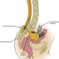
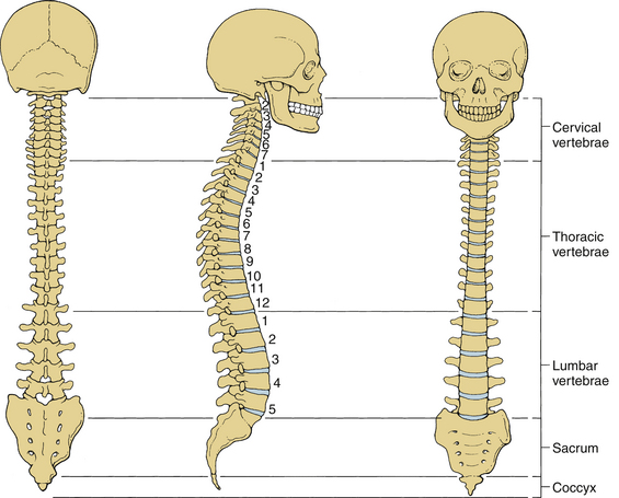
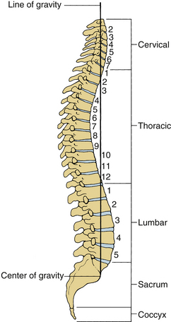
The human spinal column consists of 33 vertebrae interconnected by intervertebral discs, facet capsules, and ligaments. Normally, there are 7 cervical (C1-7), 12 thoracic (T1-12), 5 lumbar (L1-5), 5 fused sacral (S1-5), and 4 separate coccygeal bones. The first three regions are flexible. The most common variations include sacralization of the fifth lumbar vertebra or lumbarization of the first sacral vertebra. Ventral and dorsal views of the spinal column with the skull are shown in Figure 30-1. The normal adult vertebral column has four curvatures. The cervical and lumbar regions are lordotic and the thoracic and lumbosacral regions are kyphotic. The lordotic curvature is convex ventrally, and the kyphotic curvature is concave ventrally. The thoracic and lumbosacral kyphotic curvatures exist in utero and are called the primary curvatures. The cervical and lumbar lordotic curvatures develop with the raising of the head postnatally and the assumption of the erect posture. The cervical curvature is shallow; it begins at the dens of the axis and terminates at T2. The lumbar lordosis develops due to the upright position of the trunk. The sacral curvature is relatively smooth and concave. Variations in the disc and vertebral body dimensions form and maintain these curvatures; they are often modified by age-related changes of the vertebrae, osteophyte development, trauma, congenital malformations, neurologic disorders, and imbalances of the paraspinal muscles. The center of gravity of the spinal column generally passes from the dens of the axis through the vertebra to the promontory of the sacrum.1 The center of gravity of the body is located just ventral to the sacral promontory (Fig. 30-2). The vertebral column has different types of articulations: cartilaginous joints between the vertebral bodies, apophyseal joints between vertebral arches, unique articulations between the axis (C2) and atlas (C1), and skull-C1 articulation.
Vertebrae
Cervical Vertebrae
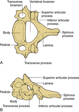
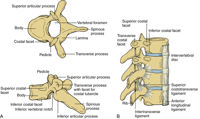
These vertebrae are smaller in size compared with those in the thoracic and lumbar regions. They are cylindrically shaped and are wider in the transverse than anteroposterior (AP) diameters. The size gradually increases from C3 to C7. The pedicles are short and project dorsolaterally. They arise from the vertebral body midway between the rostral and caudal surfaces. The arch is composed of paired pedicles and articular facets, as well as the lamina and spinous processes. The laminae are narrow and overlap. The spinous processes are short and are usually bifid from C3 to C6. The transverse processes are unique. They contain the transverse foramen from C1 to C6, which transmits the vertebral artery. The anatomy of a typical cervical vertebra (C3-7) is shown in Figure 30-3. The pars interarticularis in the cervical spine is termed the lateral masses. The superior and inferior facets extend from the lateral masses. The facets from C2-3 to C6-7 are oriented approximately 45 degrees with respect to the horizontal and are aligned with a coronal orientation to their surfaces. The first cervical vertebra (C1), or atlas, is ring shaped and supports the cranium. The atlas consists of a bony ring with stout lateral masses and anterior and posterior arches. It has large lateral masses containing the horizontally oriented facet surfaces. Rostral facets articulate with the occipital condyles of the skull, and the inferior facets articulate with the rostral facets of C2. The axis (C2) has a unique shape with a transitional morphology; it has a well-developed vertebral body with the odontoid process projecting rostrally. Its broad sloping superior facets extend laterally from the body.
Thoracic Vertebrae
These vertebrae are somewhat heart shaped and are intermediate in size between the lumbar and cervical vertebrae. The anatomy of a typical thoracic vertebra is shown in Figure 30-4A. It exhibits costal facets on each side at the junction of the body and pedicle and on transverse processes. These facets are unique (Fig. 30-4B). The costal facets are also seen on the transverse processes (except for T10-12). Vertebrae at the rostral and caudal regions have some transitional morphologic features; that is, T1 to T4 vertebrae have some cervical features, and T9 to T12 have some lumbar features. The surface area gradually increases from T1 to T12. The middle four vertebrae have almost equal lateral and AP dimensions. Lateral dimensions increase toward the cervical and lumbar extremes of the thoracic region. The spinous processes of the first, second, eleventh, and twelfth vertebrae are horizontal; the third, fourth, ninth, and tenth are oblique; and the fifth to eighth spinous processes overlap and are long and vertical. The size of transverse processes increases progressively from T1 to T12. The cervical features of T1 include the superior vertebral notch, and the lumbar features of T12 include the lateral direction of the inferior articular processes. The laminae are broad and sloping, and they overlap one another like shingles on a roof. The thoracic facets are oriented along the coronal plane. At the thoracolumbar junction, they assume a more oblique sagittal orientation.
Lumbar Vertebrae
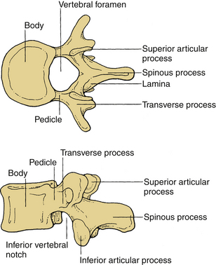
Vertebral bodies in this region are the largest and typically increase in the diameter caudally. They are larger in the transverse width than their AP diameter; a concavity of the vertebral body gives rise to an hourglass profile and a kidney-shaped cross section. The bodies of L1-2 vertebrae are deeper dorsally. The L4-5 vertebrae are deeper ventrally, whereas the L3 vertebra is transitional. The laminae are relatively broad, wide, and minimally overlap. The interlaminar spaces are covered by the ligaments and by large oblong and horizontal spinous processes. Long, thin, slender horizontal transverse processes incline slightly rostrally in the lower two lumbar segments. The transverse process of L3 projects the farthest and that of L5 spreads ventrally. The fifth lumbar vertebra represents the transition from the lumbar to the sacral spine. It is substantially taller ventrally. This contributes to the lumbosacral angle. The thick and conical transverse process arises from the junction of the pars and the pedicle of L5. The anatomy of a typical lumbar vertebra is shown in Figure 30-5.
Sacrum and Coccyx
The sacrum is formed by the fusion of the costal ligaments and the transverse processes. It is triangular in form, concave, and relatively smooth on its pelvic surface. It is convex and highly irregular dorsally. Five sacral bodies are demarcated by four transverse lines that end laterally in four pairs of ventral sacral foramina. The bilateral foramina are rounded laterally to indicate the courses of the emerging nerves. The coccyx may be a single bone fused from coccygeal elements, or the first segment may be separate from the other. These vertebrae are reduced in size, and they have no laminae, pedicles, or spinous processes.
Intervertebral Discs
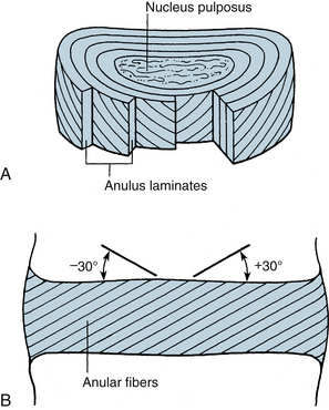
The most rostral intervertebral disc space is located between the second and third cervical vertebrae and the most caudal disc is between the L5 and S1 vertebrae. Twenty-three discs span the vertebral column between C2 and S1. Discs demonstrate regional geometric variations that parallel morphologic differences in the vertebral bodies. The discs account for approximately one third to one fifth of the total height of the vertebral column. Four concentrically arranged components are often identified in the intervertebral discs: an outer alternating layer of collagen fibers that form the peripheral rim of the anulus fibrosus, a fibrocartilage component that forms a major portion of the anulus fibrosus, a transitional region between the central nucleus pulposus where the anulus and nucleus merge, and the nucleus pulposus. The core of the disc, termed the nucleus pulposus, is made of a soft, pulpy, highly elastic mucoprotein gel. The nucleus contains various mucopolysaccharides with relatively few collagen fibers and a high water content. The anulus fibers pass obliquely from the vertebral body above and below and are arranged in a helicoid manner. The anulus is composed of concentric layers of fibrous tissue. The orientation of the fibers within each layer is the same. The orientation of the fibers in adjacent layers differs by 30 degrees (Fig. 30-6). The disc undergoes age-related changes. At birth, the disc has four distinct anatomic regions. However, the distinguishing features disappear as age transforms the disc into fibrocartilage and the number and size of the collagen fibers increases. With age, the macromolecular framework consists of collagen, proteoglycans, a noncollagenous matrix of proteins, glycol proteins, and small amounts of elastin. The elastic fibers are made of a central amorphous zone and a peripheral rim of dense microfibers. The arrangement of the fibers in the nucleus is irregular. The disc is approximately cylindrical with different ventral and dorsal heights. Typical cross sections of the disc resemble an ellipse in the cervical region, a rounded triangle in the thoracic region, and an ellipse in the lumbar region. Generally, midthoracic discs are mostly circular in cross section. In contrast, midcervical intervertebral discs are less circular. Like the vertebral body, cross-sectional areas of the disc increase from C2 to T1.
Ligaments
Ligaments are multilayered and are composed primarily of elastin and collagen. Ligaments connect adjacent vertebrae and may extend over several segments along the spinal column. Ligaments and joint capsules, while permitting normal spinal motion, restrict excessive motion.
Interspinous and Supraspinous Ligaments
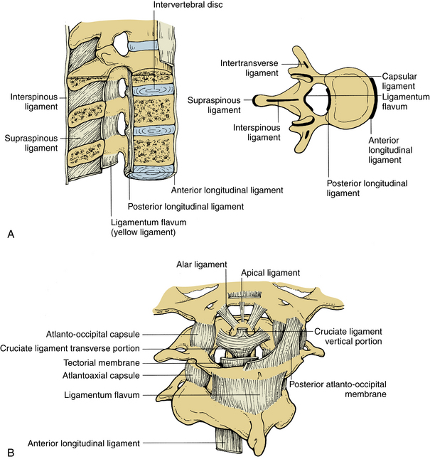
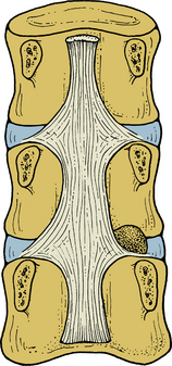
These ligaments connect the adjacent spinous processes. They are composed predominantly of elastin. The interspinous ligaments attach from the base to the tip of each spinous process. They start at C2-3 and terminate at L5-S1. Both spinous ligaments are most prominent in the lumbar region. In contrast, the supraspinous ligament begins at the most dorsal aspect of the spinous process of C7 and continues into the lumbosacral region. The supraspinous ligament is primarily associated with the ligamentum nuchae of the neck contacting the spinous processes at their tips. It is the continuation of the ligamentum nuchae in the cervical spine. The ligament fibers end between the L3 and L5 levels. Figure 30-7A illustrates the ligamentous structures in the sagittal and axial planes.
Upper Cervical Spine Ligaments
Upper cervical ligaments span from the occiput to C2 (see Fig. 30-7B). Beginning ventrally, the anterior longitudinal ligament is renamed as the anterior atlanto-occipital membrane from C1 to the occiput. The apical ligament attaches from the tip of the odontoid process of C2 to the basion of the occiput. The alar ligaments connect the rostrolateral aspect of the odontoid process and run obliquely to the occipital condyles. The cruciate ligament has ascending and descending bands and a strong transverse portion that courses dorsal to the odontoid process and attaches to tubercles on the medial aspects of the lateral masses of the atlas. The vertical cruciate ligament attaches from the occiput, just dorsal to the apical ligament, and intertwines with its transverse portion. The descending band attaches to the dorsocaudal aspect of the body of C2. The tectorial membrane attaches to the ventral one third of the basiocciput just dorsal to the vertical cruciate ligament. This ligament tapers caudally to become continuous with the posterior longitudinal ligament. Finally, the posterior atlanto-occipital membrane connects the rostral aspect of the dorsal arch of C1 to the occiput.
Muscles
In the thoracic region, the longus coli muscle extends only a few segments. In the lower thoracic and upper lumbar region, however, the lateral muscle groups are prominent, especially the psoas, intertransverse, and quadratus lumborum muscles. The iliopsoas muscles originate from the lateral aspects of the vertebral bodies and extend to the femur. As in the rest of the spine, the intertransverse muscles extend between the transverse processes. The quadratus lumborum also originates from the transverse processes and runs obliquely to the lateral ileum. Beneath the trapezius muscle, the splenius capitis muscle arises from the lower ligamentum nuchae and the cervical and upper six thoracic transverse processes, to attach to the occiput. The narrowest muscle, the splenius cervicis, originates only from the upper six thoracic spinous processes to insert on the posterior tubercles of C1 to C3. The adjacent deeper layer includes the semispinalis capitis and semispinalis cervicis muscles. The more medial semispinalis cervicis arises from the transverse and articular processes of the upper thoracic vertebrae inserting into the spinous process of the cervical spine. The lateral muscle originates from the transverse processes of C3 to C6 and inserts on the occipital bone. The deepest muscles of this group include the iliocostalis and longissimus cervicis, which arise from the upper thoracic ribs and transverse processes, respectively, to end on the transverse processes and facets of C4 to C7. Other deep muscles include the rectus capitis and capitis obliques, which serve as head extensors.
Deep to the erector spinae muscle lie the paravertebral or transverse spinal muscles. These muscles, including the semispinalis discussed previously, have their origins primarily from the vertebral transverse process and insert into the spinous process. The semispinalis group is continuous in the cervical and thoracic regions. The multifidus muscle is different in the cervical and lumbar areas, where the attachments are to the articular joint, but in the thoracic region the attachments are to the transverse processes. This muscle is thickest in the lumbar region.
Spinal Cord
The spinal cord and nerve roots traverse the spinal canal. The spinal cord is approximately 40 to 45 cm long in the adult and usually terminates at L1-2. The rostral cord at the level of the foramen magnum is continuous with the medulla oblongata. The dura mater, the pia mater, and the arachnoid are the three membranes that cover the spinal cord. The spinal cord is suspended in the spinal canal by dentate ligaments. These arise from the pia and are attached to the dura. Usually, the spinal cord terminates approximately at the caudal aspect of the L1 vertebral body. The cauda equina consists of the nerve roots, which have not exited through their neural foramina. Spinal nerves are composed of a dorsal sensory root and a ventral motor root. With the exception of the C1 and C2 contributions to the spinal accessory nerve, nerve roots leave the spinal canal via the neural foramina. Anatomically, the spinal cord is divided into five sections: 8 cervical, 12 thoracic, 5 lumbar and 5 sacral, and 1 coccygeal. Figure 30-8A shows a schematic of the spinal cord, indicating the relationship among spinal segments, nerves, and vertebral bodies.
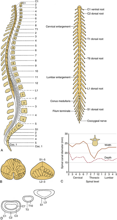
(A, Modified from Carpenter MB: Human neuroanatomy, 7th ed, Baltimore, 1976, Williams & Wilkins. B, From Benzel EC: Stability and instability of the spine. In Benzel EC, editor: Biomechanics of spine stabilization, principles and clinical practice, New York, 1995, McGraw-Hill, pp 25–40. C, Data from references 67–70. D, From Sances A Jr, Weber RC, Larson SJ, et al: Bioengineering analysis of head and spine injuries. Crit Rev Bioeng 5:79–122, 1981.)
The tracts within the spinal cord in the cervical and thoracic regions and nerve roots in the lumbar region are somatotopically oriented. The cortical spinal tracts are somatotopically arranged so that hand function is located more medially, whereas the foot function is located laterally. The spinothalamic tract is arranged so that hand sensation is located most medially and ventrally, and the sacral sensation is located most dorsally and laterally. The posterior columns are similarly arranged in a somatotopic manner. In the lumbar region, the nerve roots are arranged so that the lower sacral segments are located most medially and the exiting upper lumbar regions most laterally (Fig. 30-8B).
In a normal spine, spinal canal dimensions and hence the subarachnoid space are generous except in the midthoracic region (Fig. 30-8C). In the case of preexisting spinal stenosis, the factor of safety is reduced. This is important during a spinal instrumentation procedure that might impinge on the neural elements (e.g., sublaminar wire or hook placement). The lumbar spinal canal depth does not change significantly as one descends from the upper to the lower lumbar regions; however, its width increases (see Fig. 30-8C). The lumbar and sacral spinal canal cross-sectional areas are also more generous than in other areas of the spine. It contains the cauda equina, which consists of peripheral nerves and is relatively resistant to traumatic insults. For both reasons, posttraumatic neural element injury in the lumbar region is less severe than that associated with comparable deformation in the other regions of the spinal column, particularly the midthoracic area. The respective shapes of the typical spinal canal in the cervical, thoracic, and lumbar regions are depicted in Figure 30-8D.
Fundamental Biomechanics
Biomechanics is defined as the application of the principles of engineering and computers to solve biologic problems. Clinical biomechanics of the spine refers to the understanding of the normal and the pathologic functions of the human vertebral column due to the application of mechanical insult. The insult could be in the form of traumatic dynamic forces, deformations, and/or slowly applied loads to the spine.2 Several terms are explained to facilitate a better understanding of clinical spinal biomechanics.
Cartesian Coordinate System
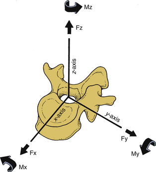
The right-handed Cartesian system of reference is commonly adopted in spine biomechanics. The system consists of three axes: x, y, and z. Rotational and translational movements can occur along and about these axes. Translational movements are considered positive if the movements occur along the positive direction of the axis; it is considered negative if the moments are in the negative direction. Similarly, a clockwise rotation around an axis looking from the origin of the coordinate system toward the positive direction of the axis is termed positive rotation, whereas the counterclockwise rotation is termed negative. Figure 30-9 illustrates the right-handed Cartesian coordinate system of reference with the z-axis oriented along the caudal to rostral direction, the x-axis along the dorsal to ventral direction, and the y-axis along the right-to-left direction. For the right-handed system, this results in a positive flexion moment (extension being negative), positive moment left-to-right lateral bending (right-to-left lateral bending is a negative moment), and positive twisting right axial rotation moment (left axial rotation is a negative moment). This reference system has been adopted by the American Standard for Testing Materials. Once the coordinate system of reference is chosen, the force vector can be divided into its components.
Strain is defined as the change in unit length (linear) or change in unit angle (shear) in the body subjected to a force (vector). There are two types of strain: normal and shear. Normal strain is defined as the change in the length divided by the original length. Shear strain is defined as the change in the right angle (90 degrees). When a deformable body is subjected to a load vector, deformations occur, resulting in strains. The deformation along the direction of the force application is termed axial strain, whereas the deformation transverse to the direction of application of the force is often termed the transverse strain. The ratio of the lateral (transverse) to the longitudinal (axial) strain is termed Poisson’s ratio.
Force Deformation Response
Because of the deformability characteristics of the spine, the application of an external force or a load vector results in deformations. Energy is frequently used to relate the force and the deformation; it represents the amount of work done by a force on a body. It is defined as the area under the force deformation curve. In contrast, stiffness is defined as the ratio of force to deformation. Because the force deformation characteristics of a spinal structure are not always linear (Fig. 30-10), the most linear portion of the curve is often selected for obtaining the maximum stiffness of the structure. Analysis of the typical force deflection characteristics of the spinal structure (example of a functional unit) is given subsequently. Response is nonlinear; that is, force does not increase linearly with the deformation or vice versa. Within the principles of structural mechanics, this biomechanical load deflection response has been classified into the physiologic loading phase; the traumatic loading phase; and the failure, or the posttraumatic, loading phase. The stiffness response of the structure has been used to derive these biomechanical classifications. This system has been used to design a schema to evaluate the onset of spinal injury due to external load. This may help define the mechanism of spinal disorders.
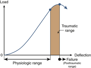
In the physiologic loading phase, the spinal structure acts as an integral unit, and the stiffness increases gradually to a maximum value. During this phase, the structure obtains its highest stiffness; consequently, its resistance increases with the externally applied loads. This region represents the highest mechanical efficiency domain in the structural response. Trauma does not occur during this region of loading. With the increase in the application of load, yielding of the structures occurs. This is identified biomechanically by the onset of decreased stiffness for the first time during the loading process. Previous studies have demonstrated microfailures during this phase of loading.3 The end of this traumatic range is characterized by changes in the stiffness that correspond to the ultimate load-carrying capacity of the structure. After reaching its peak during the physiologic loading phase, the stiffness gradually decreases to zero at the end of the traumatic loading phase, indicating that the structure has reached its ultimate load-carrying capacity. In the subsequent phase (i.e., the posttraumatic loading phase), the structure responds with negative resistance; that is, an increase in the deformation results in a decrease of the load. Trauma has been identified on radiographs when the structure has been loaded to this level. Based on the simple fundamental force deformation response and using the stiffness as a mechanics-based criterion, studies have indicated that microtrauma may initiate the loss of a local component before the structure has reached its ultimate load-carrying capacity.4,5 In other words, even under subfailure loading, the structure may exhibit signs of weakness or microfailure.
Coupling
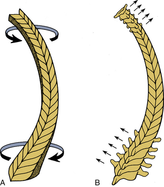
Because of the three-dimensional nature of the spinal structure, motions are coupled. Coupling is defined as the capacity of the spine to move in translations and/or rotations independent of the principal motion. In other words, it represents obligatory movements of the spine (translations or rotations) that always accompany a primary motion. Both principal and coupled motions exist in the spine.6 Principal motion can be defined as the motion associated with the direction or the plane of application of the external force. Any out-of-phase motion is the coupled motion. For example, axial rotation of the upper cervical spine is usually coupled with lateral bending.7 Similarly, in the lower cervical spine, axial rotation and lateral bending of the vertebra in the opposite direction are usually coupled (Fig. 30-11).
Bending Moment
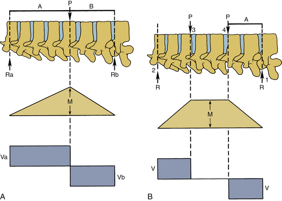
The force vector may act on a lever arm to cause a bending moment. A diagram indicating the amount of bending moment at various sections of the structure is termed the bending moment diagram. Frequently, in spinal biomechanics, three-point bending (Fig. 30-12A) and four-point bending (Fig. 30-12B) are often used. In three-point bending, the force is applied at the middle of the length of a structure with the structure being supported at its two ends.2 This results in a triangular-shaped bending moment with the maximum moment under the point of load application. In four-point bending, the spinal structure is subjected to two equal loads placed at equal distances from the center, and the structure rests on two simple supports. This results in a trapezoidal-shaped bending moment diagram, in which the bending moment is constant between the points of load application. In this region, the sheer force is zero. A pure moment is sustained by the structure between the points of loading, and consequently the results obtained using a four-point bending technique can be applied for a pure bending moment situation.
Instantaneous Axis of Rotation
If the load is applied along the spinal long axis, it is called an axial or a longitudinal load. This load may result in structural buckling. The buckling load represents the highest load that the column can sustain before failure when the load is applied in the longitudinal manner. The instantaneous axis of rotation (IAR) defines characteristic movements during rotation of a vertebra. It is the point about which the vertebra rotates. The IAR is defined as the axis perpendicular to the plane of the motion of the body and passing through a point within the confines of the body or outside the body that does not move is the IAR for that motion at that point in time. Table 30-1 includes additional details.
| Description | Units |
|---|---|
| Displacement | mm |
| Elastic modules | N/cm2 |
| Energy | N-m, J |
| Force | N |
| Moment | N-m |
| Rotation | Degrees, rad |
| Strain | Nondimensional |
| Stress | N/cm2, MPa |
| Torque | N-m |
| Stiffness | N/mm |
| Flexibility | mm/N |
Clinical Biomechanics
Internal Deformation
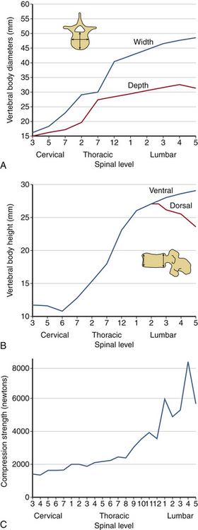
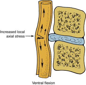
The human spinal column resists external mechanical forces by undergoing internal deformations. The mechanical and structural changes depend on the type of force vector applied to the spine. The following terms are used routinely: flexion, extension, subluxation, rotation, and distraction (Table 30-2). Flexion refers to a forward bending moment. Extension refers to a backward bending moment. Subluxation refers to an AP or posteroanterior shear. Rotation refers to an axial twist or torsion. Distraction refers to stretch or tension. Due to the anatomic characteristics of the vertebral column, the human spine is under the action of compressive force applied in an eccentric manner. Depending on the location of the center of gravity (see Fig. 30-2), this force generally induces a flexion moment. One of the principal actions of the vertebral body is to resist compressive forces. The compressive force resisted by the body gradually increases from the cervical to the lumbar levels. As described earlier, the width, depth, and height of the vertebral bodies increase from the rostral to caudal direction. This geometric phenomenon permits an efficient load-carrying capacity of the structure of the lumbar region compared with the cervical region. The exception is the height of the C6 vertebral body, which is less than C5 and C7; the height of the lower lumbar vertebral body is usually less than that of L2. Although the general shape of the vertebral body is cylindrical, the concave geometry of the dorsal aspect of the vertebral body (the surface facing the spinal canal) is significant in ventral spinal operations where screw purchase of the dorsal vertebral body cortex is critical. Misinterpretation of the lateral radiograph may lead to neural impingement by the screw. Figure 30-13 presents properties of the vertebrae from the cervical to the lumbar region. The compression strength of the vertebral body shown in Figure 30-13C indicates the general trend. Variations are due principally to the sample size, population, and age-dependent characteristics of specimens tested in the literature. An understanding of the tolerance levels under compression for the vertebral bodies is important in fracture fixation techniques.
| Clinical | Bioengineering |
|---|---|
| Extension | Rearward bending |
| Flexion | Forward bending |
| Lateral flexion | Lateral bending |
| Angulation | Rotation |
| Rotation | Torque/twist |
| Stretch/distraction | Tension |
| Subluxation | Shear |
Facet Joints
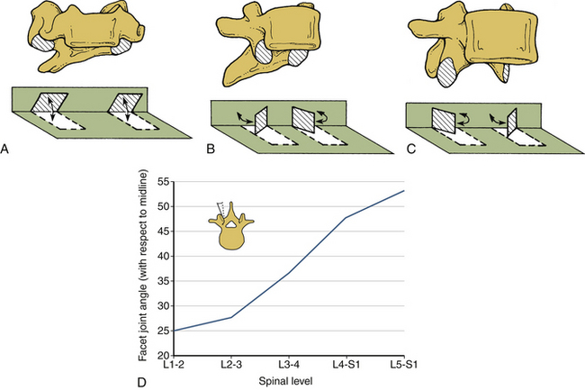
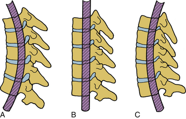
The facet joints do not substantially support axial compressive loads unless the spine is in extension. Change in the orientation of the facet joints alters the mobility—and hence the load-carrying capacity—of the spinal column under different force vectors. For example, the primarily coronal orientation of the facet joints in the cervical spine, compared with an intermediate orientation in the thoracic region and a sagittal orientation in the lumbar region, account for the alterations in the magnitudes of the rotations of these regions. In particular, the facet joint orientation changes substantially from L1 (approximately 25 degrees) to L5-S1 (approximately 50 degrees). Figure 30-14 depicts the orientation of the facet joints in the cervical, thoracic, and lumbar regions. The general sagittal plane orientation of the facet joints in the lumbar region renders the lumbar spine unable to resist flexion or translational movements, whereas the ability to resist rotation is substantial (Fig. 30-15). Relatively decreased incidents of subluxation found clinically can be attributed to a nearly coronal facet orientation at the L5-S1 level. It is well known that the subluxation is more common at L4-5 than at L5-S1 despite the relatively oblique orientation of the L5-S1 disc interspace. The ability of the cervical spine facet joints to resist flexion and extension, lateral bending, and rotation is relatively reduced because of the coronal plane orientation. Consequently, such movements are substantial in the cervical spinal region.
Spinal Cord
The spinal cord participates with the vertebral column in configuration changes due to alterations in body positioning. The susceptibility to injury varies with the specific abnormalities of the column. The physical properties of the spinal cord and related nerve roots, dentate ligaments, and pia and dura mater have been reported.8,9 The spinal cord is part of a continuous tract originating in the mesencephalon and extending to the point where the nerve roots exit. This structure participates in the physical alterations, with the predominant effects occurring at the local level of distraction. Similar to the biomechanical response of a functional spinal unit, distraction in the cadaver cord demonstrates a load displacement curve with two phases. Large initial displacements occur with small force levels, demonstrating the elastic flexibility of the cord. However, this initial flexibility is followed by stiffening in which additional stretch or distraction requires higher load levels.10
In flexion, the spinal cord elongates within the spinal canal and decreases in the AP diameter. This induces increased axial tension in the axon cylinders of the white matter tracts and lesions of the vertebral canal that compromise the cross-sectional area; especially those processes ventral to the spinal cord call for the local and generalized increases in axial tension within the spinal cord. In extension, the spinal cord shortens and increases in the AP diameter with relative relaxation of the axon cylinders. The corresponding decreased cross-sectional area of the canal occurring from the dorsal bulging of the anulus, as well as the infolding of the ligamentum flavum and scaffolding of the lamina, may result in a “pincerlike” action on the cord. Studies indicate that irreversible spinal cord damage occurs when the compression exceeds approximately 30% of the initial cord diameter. Tensile forces applied to the spinal cord in the neutral position produce a relatively even load distribution across the structure, but if the cord undergoes bending, compressive forces increase on the concave side, causing increasing distractive forces on the convex side (Fig. 30-16). Shear forces, in contrast to tensile forces, are maximal toward the center of the cord. By definition, shear forces act in a perpendicular plane to the tensile forces. Interaction of these force vectors applied to the various regions of the spinal cord during flexion indicates the potential for a complex pattern of injury. Increases in the shear stresses in the central region of the cord occur due to the “pincerlike” action, during a sudden forceful hyperextension.
Pedicle
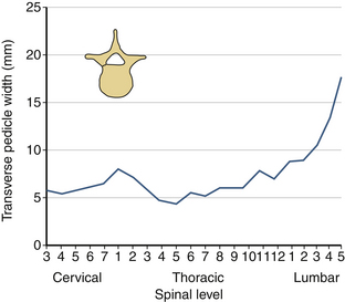
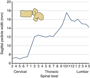
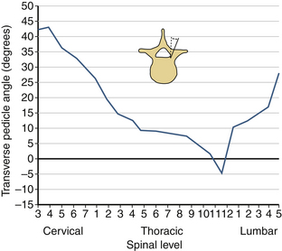
The sagittal pedicle height increases gradually from the cervical to thoracolumbar region and decreases caudally in the lumbar spine. The transverse pedicle width decreases from the cervical to the midthoracic area and then increases caudally in the lumbar spine, favoring the placement of pedicle screws in the lumbar spine (Fig. 30-17). Because of the generous dimension, a small variation in the pedicle height in the lumbar region is clinically insignificant (Fig. 30-18). The decrease of the transverse pedicle angle from the cervical to the thoracolumbar region, and then a caudal increase in the lumbar spine, necessitates a wider angle of approach for the placement of pedicle screws in the lower lumbar spine (Fig. 30-19). An appreciation of vertebral anatomy is important for pedicle screw placement in the sacral region. There is, however, usually a great margin of safety for screw placement in this region of the vertebral column.
Intervertebral Disc
Unlike the vertebral body, discs cannot be tested in isolation, that is, the adjacent supports of the vertebra are necessary to determine its gross biomechanical properties. Routinely, functional segments (vertebra-disc-vertebra structure with or without the posterior complex) are used to determine the strength.11 Biomechanical testing has indicated that the first component to fail in a functional spinal unit is the end plate.3,12 In the lumbar spine, normal discs respond with higher load-carrying capacity and higher stiffness compared with degenerated discs.4 Studies have also demonstrated the movement of the nucleus material into the cancellous core of the vertebral body under discographic techniques.13 Initiation of trauma identified biomechanically by the first decrease of stiffness within the specimen still able to resist further increases of load, occurs with the movement of the nucleus pulposus into the vertebral end plate, causing its rupture.14 Under symmetrical axial compressive loading, the disc bulges in the transverse plane.15 The compressive structural property of the disc does not contribute to the commonly observed disc herniation in the dorsal lateral direction; it depends primarily on the specific loading situations, which include compression, combined with other loading modes.16 Although the disc is never subjected to a direct uniform tension along its entire cross section, certain modes of loading induce tensile forces in different regions of the disc. For example, under physiologic conditions, the anulus of the disc is subjected to tensile forces. Under flexion, the dorsal aspect of the disc is subjected to tension; in extension the ventral part of the disc experiences tension. In right lateral bending, tensile forces are resisted by the disc on the left side; in left lateral bending, tensile forces are resisted on the right side of the disc. From this point of view, the disc resists tensile forces locally, although the applied load vector may be in a different loading mode.
Depending on the spinal level, the disc resists a considerable amount of rotation or torsional forces. The average failure torque for a nondegenerated disc is 25% higher than a degenerated disc. Similar to the case of an axial compressive load-deflection curve on a spinal unit, the torque versus angle curves are nonlinear. With increasing rotation, the torsional stiffness increases. Whereas the end-plate integrity alters in compression, under torsion the end plates generally remain intact. In experimental in vitro human cadaver studies, cracking sounds emanate secondary to injury to the anulus. This may have a clinical correlation in the fact that patients with low back pain often report that they have experienced a “pop” in the back.
Ligaments
Although ligaments possess three-dimensional geometry in terms of attachment and insertion, from a biomechanical perspective they are uniaxial structures; that is, they respond to direct tensile forces. Figure 30-20 illustrates the tensile load-carrying capacity of spinal ligaments. The effectiveness of a ligament depends on the morphology and the moment arm through which it acts. To appreciate the contribution of a ligament to the load-carrying capacity of the spine, one must consider the anatomic location as well as the strength of the ligament under tensile forces. A very strong ligament that functions through a relatively short lever arm may contribute less to the stability than a weaker ligament working through a longer lever arm (Fig. 30-21). For example, although the posterior longitudinal ligament is relatively strong, it offers little resistance to flexion because of its ventral attachment. In other words, because the ligament is closer to the IAR than the interspinous ligament, it is less effective (Fig. 30-22). This is similarly true for the ligamentum flavum. This ligament is deficient in the midline; that is, a longitudinal midline cleavage plane exists. This property facilitates surgical entrance to the epidural space. The ligamentum flavum is not lax except under hyperextension. This factor, along with its high elastin content, minimizes the likelihood of buckling during extension, which might result in dural sac compression. The dorsal location of the posterior longitudinal ligament relative to the IAR, combined with a shorter moment arm, renders it a weak resistor of flexion. Although the capsular ligaments have a shorter lever arm, particularly in the cervical spine, they play a large role in the maintenance of spinal stability. This stems from their increase of strength compared to their counterparts in the thoracic and lumbar regions.
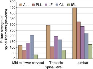
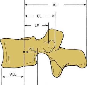
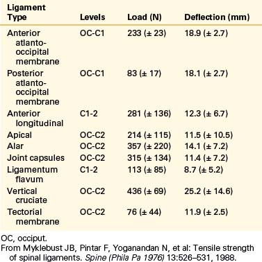
Biomechanical studies have shown that the ligaments farthest from the IAR, in general, demonstrate the highest amount of strength.17,18 Variations in strength and stability can be related to anatomy and loading characteristics.19 The failure deflection generally increases with the distance from the vertebral center of rotation with a general increase in strength moving from cervical to lumbar levels. Ligaments in the convex side of the spinal curvature are generally stronger. Additional increases in the strength are observed at the thoracolumbar and cervicothoracic junctions. Based on an exhaustive study of 132 samples, Pintar et al. determined the biomechanical parameters for the six major ligaments of the lumbar spine.20 Responses based on mechanical characteristics and anatomic considerations were grouped into T12 to L2, L2 to L4, and L4 to S1 levels maintaining individuality and nonlinearities. Using nondimensional analyses and accounting for interspecimen variability, biomechanical parameters in terms of the stiffness, energy, stress, and strain to failure, along with cross-sectional area and original length have been computed for the longitudinal ligaments, joint capsules, ligamentum flava, and interspinous and supraspinous ligaments (Fig. 30-23 and Tables 30-3 to 30-5). Upper cervical ligament data are available in the literature (Table 30-6).20
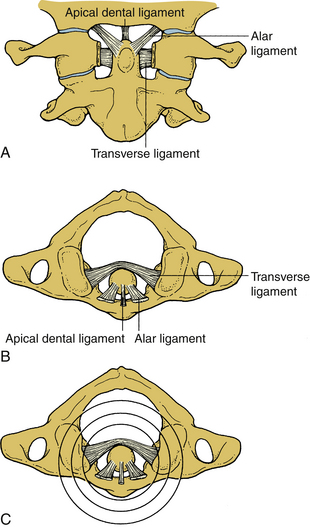
TABLE 30-3 Values of Cross-Sectional Area and Original Length for Ligaments of the Lumbar Spine (T12-S1)
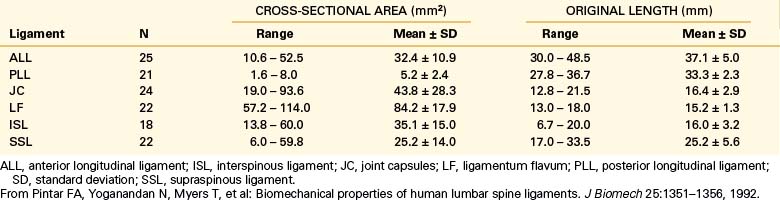
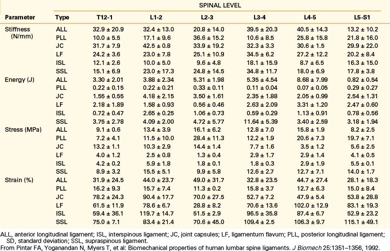
TABLE 30-5 Overall Mean Values of Stiffness (N/mm–1) for Ligaments of the Lumbar Spine (T12-S1)
| Ligament | Mean ± SD |
| ALL | 33.0 ± 15.7 |
| PLL | 20.4 ± 11.9 |
| JC | 33.9 ± 10.7 |
| LF | 27.2 ± 9.2 |
| ISL | 11.5 ± 6.6 |
| SSL | 23.7 ± 10.9 |
ALL, anterior longitudinal ligament; ISL, interspinous ligament; JC, joint capsules; LF, ligamentum flavum; PLL, posterior longitudinal ligament; SD, standard deviation; SSL, supraspinous ligament.
From Pintar FA, Yoganandan N, Myers T, et al: Biomechanical properties of human lumbar spine ligaments. J Biomech 25:1351–1356, 1992.
TABLE 30-6 Mean and Standard Deviation Values of Force and Deflection at Failure for Human Upper Cervical Spinal Ligaments
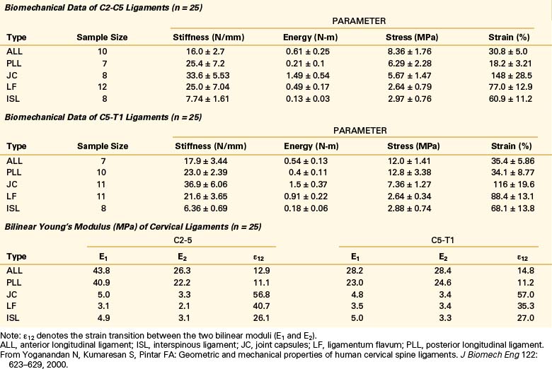
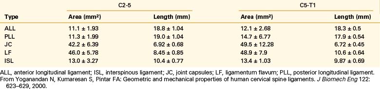
Yoganandan et al. conducted an analysis of mid- to lower cervical spine ligaments.21 Using in situ testing and cryomicrotomy, properties of the C2-5 and C5-T1 ligaments were determined. Data were reported in the form of stiffness, energy, stress, strain, and modulus of elasticity (Table 30-7) and area and length (Table 30-8). In the original article, Yoganandan et al. provided force-deflection curves as a function of ligament type and vertebral level.
Muscles
The force resisted by the muscle depends on factors such as its length at the initiation of contraction. The maximum force develops at approximately 125% of the resting length of the muscle; in contrast, at approximately 50% of its resting length, the muscle develops very low force. The muscle stress (the maximum force per unit area) ranges from 30 to 90 newtons/cm222 Electromyographic (EMG) studies are used to determine muscle action. Generally, the relationship between an EMG and a muscle’s distractive force is monotonic. Whereas muscles contribute significantly to maintain the stability of the spinal column under physiologic conditions, the action of the muscles is not clearly understood under dynamic forces. During flexion, most of the back muscles are active; at full flexion, however, they often become inactive except for the iliocostalis dorsi. EMG activity in the back muscles occurs at the beginning and at the completion of the full extension from the neutral position, with only slight activity between these two extremes. The abdominal muscles, in contrast, respond with increasing activity during bending, and in this mode, the activity of the muscle increases primarily on the ipsilateral side. During axial rotation, the erector spinae muscles on the ipsilateral side and musculi rotators on the contralateral side are active. Abdominal muscles show slight activity during rotation.
Regional Characteristics
Cervical Spine
Upper Cervical Spine and Craniocervical Junction
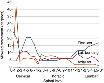
Atlanto-occipital joints allow flexion-extension. A minimal degree of lateral bending coupled with minimal rotation is allowed. Most cervical rotation occurs about the occiput-C2 complex. The movements allowed in the craniocervical region are shown in Table 30-9. Although movement in the upper cervical region does not occur in all planes and in rotation at each spinal level, its sum from occiput to C2 exceeds that observed in any other region of the spine (see Fig. 30-23). Anatomic features of the upper cervical spine offer several fixation points for instrumentation constructs and sites for bony fusion attachment. Upper cervical spine surgery is complicated by difficulties associated with calvarial fixation, unique anatomy of the upper cervical vertebrae, and substantial spinal movements in this region.23
| Joint | Motion | Range of motion (degrees) |
|---|---|---|
| Occiput-C1 | Combined flexion/extension | 25 |
| Lateral bending (unilateral) | 5 | |
| Axial rotation (unilateral) | 5 | |
| C1-2 | Combined flexion/extension | 20 |
| Lateral bending (unilateral) | 5 | |
| Axial rotation (unilateral) | 40 |
From Maiman DJ, Yoganandan N: Biomechanics of cervical spine trauma. Clin Neurosurg 37:543–570, 1991.
The atlantoaxial region represents a unique integration of anatomy and function, allowing three-dimensional movement of the head through both individual and coupled motions. At the atlanto-occipital joint, 13 to 16 degrees of flexion-extension occurs. In addition, more than 8 degrees of lateral bending occurs without rotation. At the atlantoaxial junction, flexion-extension is significant (10–13 degrees). The most significant motion at C1-2 is 40 degrees of unilateral axial rotation, which represents 40% of the total rotation seen in the cervical spine. In any forced rotation of the entire cervical column, maximum rotation occurs at C1-2 before use of potential rotation in the lower cervical spine.24
Translation also occurs in the upper cervical spine, although it is normally limited to approximately 2 mm, primarily because of the anatomic relation between the odontoid process, arch of C1, and transverse atlantal ligament. Other motion limiters include those that inhibit hyperflexion: the relationship between the anterior lip of the foramen magnum and the odontoid process at the occiput-C1 and low elasticity of the tectorial membrane at C1-2. Extension limiters include the tectorial membrane and anterior longitudinal ligament. Rotation is contained by the contralateral C1-2 alar ligament.24
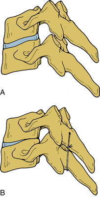
Mid- and Lower Cervical Spine
Orientation of the facet joints in the coronal plane does not excessively limit spinal movement in any direction or in rotation. An exception is extension. This orientation facilitates spinal instrumentation in certain situations. With the integrity of the facet joints and pedicles maintained, the vertebral bodies are able to equally resist axial loading, and translation instability may be effectively managed by the application of a tension band fixation construct (Fig. 30-24). Facets and the joint capsules are injured under internal tension secondary to spinal hyperflexion. Normally, they absorb approximately one fifth of the total compressive loads applied to the lumbar spine segment.25 They have an important role in resisting pathologic forces. In facetectomy studies, the shear and combined compression-flexion strength and kinematics of the spine are significantly compromised.25–29
In the lower cervical spine, primary spinal motions are related to disc integrity. Flexion-extension is distributed throughout the cervical spine a total of 60 to 75 degrees. Sagittal translation is limited to 2 to 3 mm at all cervical levels. This is a function of facets, ligaments, and discs. Thus, even small increases in translations may be harmful. Lateral bending, on the other hand, is a prominent motion, particularly above C6. Between C2 and C5 there is 10 to 12 degrees of lateral bending per spinal level, and at C7-T1 there is 4 to 8 degrees. Typically, lateral bending is coupled with axial rotation.6 This coupling in which the spinous processes are rotated in the opposite direction of the lateral bending may be a consequence of muscle contraction or the three-dimensional spatial orientation of the spinous processes (Table 30-10).2
| Maiman et al.* | Johnson et al.† | |
|---|---|---|
| Lateral bending | 64.2 (± 6.8) | |
| Rotation | 134.2 (± 17.1) | |
| Flexion-extension | ||
| OC-C1 | 16.7 (± 10.0) | 13.6 (± 6.0) |
| C1-2 | 11.6 (± 4.7) | 15.2 (± 3.8) |
| C2-3 | 17.1 (± 4.5) | 17.1 (± 3.9) |
| C3-4 | 18.1 (± 6.1) | 18.8 (± 2.2) |
| C4-5 | 13.7 (± 1.7) | 12.0 (± 1.2) |
| C5-6 | 17.6 (± 1.5) | 20.1 (± 1.6) |
| C6-7 | 21.8 (± 1.6) | 20.7 (± 1.6) |
* Maiman DJ, Yoganandan N: Biomechanics of cervical spine trauma. Clin Neurosurg 37:543–570, 1991.
† Johnson RM, Hart DL, Simmons EF, et al: Cervical orthoses. A study comparing their effectiveness in restricting cervical motion in normal subjects. J Bone Joint Surg [Am] 59:332–339, 1977.
Thoracic Spine
The thoracic spinal cord is shielded from injury by the massive regional paraspinal muscle masses and by the thoracic cage. The narrow spinal canal diameter in the upper thoracic region, however, complicates the issue. The former protects the neural elements; the latter contributes to neural injury. This may explain the increased incidence of catastrophic neurologic injuries associated with thoracic fractures. The significant paraspinal muscle mass protects the spine from injury. However, the narrow spinal canal leaves little room to spare for the spinal cord, which is easily compromised by malalignment of the spine or retropulsion of bone due to a fracture30 (Fig. 30-25). The normal kyphotic posture of the thoracic spine, with its associated predisposition to spinal fracture, amplifies all of these factors. Biomechanical effects of laminectomy on thoracic spine stability are reported.31
Lumbar Spine
Its relatively large proportions and the resumption of lordosis make this region relatively resistant to failure. Furthermore, the transition of the spinal cord into the cauda equina makes catastrophic spinal injury from trauma less likely. The caudal end of the column is associated with significant logistical therapeutic dilemmas. Frequently, an inability to obtain a solid point of sacral fixation creates surgical problems. Similarly, an appropriate bending moment is not often resisted by the instrumentation construct because of an inadequate length of the lever arm below the injury.30,32–34 Furthermore, the relatively steep orientation of the lumbosacral joint exposes the lumbosacral spine to increased translational deformations.
Spinal Stability
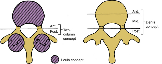
The original two-column stability concept presented by Holdsworth was based on the clinical experiences of Holdsworth and Nicoll, and the experimental work of Roaf.35–37 In the two-column definition, the dorsal column consists of the posterior ligamentous complex (i.e., the interspinous and the supraspinous ligaments, ligamentum flavum, and apophyseal joints). The anterior column consists of the vertebral body, intervertebral disc, and anterior and posterior longitudinal ligaments. Holdsworth contended that the stability depends principally on the integrity of the dorsal ligament complex.35 Consequently, a simple burst fracture with no dorsal involvement was deemed stable. A compression burst fracture with an intact dorsal complex also is stable. Unstable fractures consist of the loss of integrity of the posterior ligament complex and at least one of the components of the anterior column.
The consideration of “columns” in defining the extent of stability helps the physician conceptualize and categorize case-specific phenomena. The theory of Louis is that the spine bears weight principally by sustaining axial loads along the vertebral body, the disc, and the two facet joint complexes (Fig. 30-26) at each spinal level.38 This concept assists in the instability assessment process when predominantly axial loads are involved. Because of its obvious association with the bony columns of the spine (vertebral body and facet joints), this three-column concept of Louis assesses the bony component failure more effectively than soft tissue damage.38 Conventional radiographs and CT scans are tools to assess this type of instability. However, except for the case of a significant vertebral body failure, a correlation between the external bony injury and chronic instability may be tenuous.33 In addition, this theory does not facilitate the assessment of the distraction, flexion, and extension components of injury. The three-column concept of Denis is more applicable to this situation.39,40 This theory assists in assessing bony collapse associated with axial load bearing; it also provides insight into the assessment of the distraction, flexion, and extension components of injury (injury to the dorsal elements) of the spinal column. The three-column theory adds the concept of a middle column to the two-column theory and allows specific assessment of that component to the spinal column in the region of the neutral axis.39,40
The neutral axis is that longitudinal region of the spinal column that bears a significant portion of the axial load and about which spinal distraction or compression does not necessarily occur with flexion or extension (Fig. 30-27). Usually, the neutral axis is located in the region of the midposterior aspect of the vertebral body (i.e., the middle column of Denis).39 This also encompasses the IAR in the sagittal plane.
The middle-column definition of Denis was based on experimental studies demonstrating that transection of the entire dorsal ligament complex alone was insufficient to produce instability. However, when the posterior longitudinal ligament and the dorsal portion of the disc were also transected, instability ensued. Therefore, in the three-column spine of Denis, the middle column consists of the posterior longitudinal ligament, the dorsal anulus fibrosus, and the dorsal wall of the vertebral body; the anterior column consists of the anterior longitudinal ligament, the ventral anulus fibrosus, and the ventral wall of the vertebral body. The posterior column is the same as in the two-column approach of Holdsworth. Of the major spinal injuries defined by Denis, only minimal and moderate compression fractures with an intact posterior column should be considered stable. The two- and three-column theories differ in classifying burst fractures in terms of stability. Denis classifies the burst fracture as unstable because both anterior and middle columns are affected. All fractures and fracture/dislocations categorized as unstable by Denis demonstrated trauma in at least two of three columns. Many other definitions of clinical instability also exist. Clinical instability is also defined as the loss of the ability of the spine under physiologic loads to maintain its pattern of displacement so that there is no initial or additional neurologic deficit, no major deformity, and no incapacitating pain.11
In biomechanical literature, stability and instability are used interchangeably. Instability is the inverse of stability. Benzel defined instability as the inability to limit excess or abnormal spinal displacement. The use of the word excessive reflects the difficulty of quantifying instability in clinical situations.33 Stability has also been classified as acute and chronic. Acute instability may be categorized as vertical and limited. Chronic instability can similarly be classified into two subgroups: glacial instability and the instability associated with dysfunctional segmental motions.
Quantification of Acute Instability
Numerous authors have attempted to quantify the degree or extent of acute instability by a point system approach. White and Panjabi described a region-specific point system in which an accumulation of five or more points indicates an unstable spine.11 The system emphasizes the differences between the cervical, thoracic, and thoracolumbar and lumbar regions. These are the essential assessments of overt and limited instability as defined subsequently. The primary purpose of a stability determination is to delineate the most appropriate management scheme for patient care. Recently, Benzel presented the quantification of acute instability in subaxial cervical, thoracic, and lumbar regions based on the point system suggested earlier by White and Panjabi.33 In principle, the earlier classification was combined in such a way that regional differences were eliminated so that the point system was independent of spinal region.
The stretch test for the assessment of acute cervical spine instability by White and Panjabi involves a progressive addition of cervical traction up to 33% of the patient’s weight with serial radiographic and clinical assessments. A positive test indicating the presence of instability is the one that shows a disc interspace separation of more than 1.7 mm or a change in the angle between the vertebrae of more than 7.5 degrees between the prestretch and poststretch conditions. The merits of this test are debatable. First, it is clearly not without risk, whether those risks be immediately obvious or occult. A risk of tethering the spinal cord over a ventral mass may also exist. The most significant and least immediately recognized risk of this procedure is that of a false-negative test (i.e., the presence of stability in a real unstable circumstance). This test has been used as a determinant of eligibility for participation in contact sports.33 It should be noted that the resistance of stretching by muscle action (voluntary or involuntary) may conceal ligament deficiencies, particularly in an athlete.
Flexion-extension radiographs may also not be helpful, and in certain cases, could be misleading, particularly following trauma. If pathology is observed and iatrogenic injury via the act of flexion and extension is not incurred, they are useful.33 They are, however, not without risk if spinal instability is present. A “normal” flexion-extension radiograph may not always indicate stability (i.e., the test may be a false negative). Incomplete patient cooperation and “guarding” against excessive spinal movement due to underlying acute pathology can also disguise an injury process that, if not treated properly, may lead to catastrophe.
Anomalous Anatomy
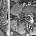
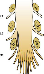
This feature is occasionally associated with structural, biomechanical, or neurologic sequelae. For example, the Klippel-Feil anomaly in the cervical spine can place excessive stress on adjacent motion segments via the application of an abnormally lengthy moment arm. This, in turn, could result in the acceleration of degenerative changes at adjacent motion segments. Similarly, the lumbarization of the L5 vertebral body (i.e., the presence of 4, instead of 5, lumbar segments) could place excessive stress at the L4-5 disc interspace. Conversely, the presence of six lumbar vertebrae could result in excessive lordosis and abnormal loading patterns that expose the lower lumber motion segments to significant stress that may lead to increased rates of disc herniation and degenerative changes. Anomalous nerve root anatomy, such as conjoined nerve roots (Fig. 30-28), can expose the patient to injury from disc herniation or trauma, due to the restriction of normal nerve root motion and mobility. In addition, the unaware surgeon may cause intraoperative iatrogenic injury if the presence of this anomaly is not evident to the surgeon prior to surgery.
Soft Tissue Biomechanics
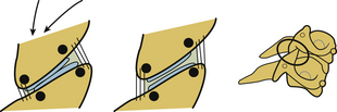
As discussed, integrity of soft tissues is vital to maintain spinal stability and physiologic function. Physiologic dysfunction in the form of pain to the neck or headache occurs due to motor vehicle rear impacts, and these injuries do not often result in osseous damage. These injuries, often termed whiplash trauma, are soft tissue related.41 Studies conducted by Yoganandan et al. have explained the mechanisms of headache and neck pain, the two most common complaints of whiplash patients. Using biomechanical tests, Yoganandan et al. documented soft tissue injuries in the form of ligament and facet joint compromise secondary to single rear impact acceleration using intact whole-body postmortem human subjects.42 Cusick et al. discussed the formation of a reverse curve during the earlier stages of the rear impact acceleration wherein the spine attains a nonphysiologic curvature (i.e., upper cervical spine flexion associated with lower cervical spine extension).42–48 Using kinematic analysis as a biomechanical basis, these studies indicated that flexion at the upper segment may stretch the posterior suboccipital structures, creating tensile forces, which may affect the related neural structures and be responsible for suboccipital headaches. The local lower cervical spinal extension indicated that the facet joint slides from the anterior to the posterior direction and the joint stretches ventrally while compressing dorsally, indicating a pinching mechanism. The sliding and the pinching mechanism result in a stretch of the joint itself. This local stretch of the lower cervical spine facet joint may be responsible for neck pain in whiplash patients. A diagrammatic representation of the facet joint pinching mechanism resulting in a stretch of the facet joint is shown in Figure 30-29. Differences have been reported between men and women with regard to cervical spine motions during rear impact, in particular, during the time of formation of the nonphysiologic S curve.48,49 Specifically, female intervertebral joints have shown a higher degree of motion than male joints at the lower cervical spine levels. These studies appear to support the clinical and epidemiologic finding that females are more susceptible to soft tissue–related injuries than males.50,51 The role of gender on the anatomic variations is discussed in the next section.
Gender Effects
The human spine exhibits anatomic and biomechanical differences between genders. It is well known that the rate of maturation process is earlier in women than men. Men have larger vertebral dimensions than women.52–54 Lumbar vertebral body heights and cross-sectional areas are greater in men than women.55 In addition, lumbar body sizes in adult and pediatric women are smaller than men, after accounting for age, stature, and total body mass.56–58 Widths of lumbar vertebrae are also smaller in women. In the adult cervical spine, sizes of vertebrae are also greater in men than women, and in particular, vertebral bodies are longer in the midsagittal plane, and the canal-to-body ratio is greater.52,53,56 Lumbar ligaments in women have decreased collagen and increased elastin.59 In a quantitated CT study of 98 adult healthy human volunteers from the North American population between the ages of 18 to 40 years, Yoganandan et al. showed that the trabecular bone densities of cervical vertebrae are greater than those of lumbar vertebrae, and furthermore, the density increases caudally in the cervical region.60,61 Also, lumbar spine density was the best predictor of cervical vertebral density. Using the same group of 98 volunteers and size-matching based on sitting height and circumference, the following parameters were extracted: vertebral width, disc-to-facet depth, and segmental support area, combining interfaced width and disc-to-facet depth.62 Vertebral width was defined as the distance between the most lateral extents of the right and left articular masses. Disc-to-facet depth was defined as the distance between the most anterior vertebral body extent and the most posterior articular mass extent. Interfacet width was defined as the distance between the posterior extents of the right and left articular masses. Segmental support area was defined as the triangular area formed by the interfacet width and disc-to-facet depth. These parameters (i.e., vertebral width, disc-to-facet depth, and segmental support area) were significantly greater in men than in women.
Regions of cervical vertebrae with specific relevance to posterior surgical procedures were evaluated for gender dependence using the quantitated CT study on 98 human volunteers.62 Pedicle width, height, length, axis length, and medial and sagittal offsets, as well as transverse and sagittal angulations, significantly depended on gender and vertebral level.63 All six linear parameters showed gender and level bias; they were larger in men than in women. In addition, the angular parameters were also gender dependent. The mean pedicle width and height data were 19% and 18% greater in men than in women. These findings are consistent with the results of a study involving the Japanese population; pedicle width and height data are 5% and 19% greater in men.64 Variations in pedicle lineal dimensions and angulations may be important in presurgical planning. Further evaluations of the mean lateral mass width and bicortical screw lengths for the Roy-Camille and Magerl techniques also indicated greater dimensions in men than women in the subaxial cervical column, although these parameters showed level dependence.65 Additionally, using unembalmed human cadaver cervical spinal columns coupled with cryomicrotomy, facet joint width, cartilage thickness, and cartilage gap (defined as the distance from the most ventral or most dorsal region of the facet joint to the location where the cartilage began to appear) were extracted from occiput to T1 levels.66 The cartilage gap in the dorsal region was greater in women than in men, and the overall mean facet cartilage thickness was lower in men than in women. The lack of adequate cartilage in females may expose the underlying adjacent subchondral bone to direct stresses during normal physiologic and traumatic loads.
Cusick J.F., Yoganandan N., Pintar F.A., et al. Biomechanics of sequential posterior lumbar surgical alterations. J Neurosurg. 1992;76:805-811.
Yoganandan N., Knowles S.A., Maiman D.J., et al. Anatomic study of the morphology of human cervical facet joint. Spine. 2003;28:2317-2323.
Yoganandan N., Kumaresan S., Pintar F.A. Geometric and mechanical properties of human cervical spine ligaments. J Biomech Eng. 2000;122:623-629.
Yoganandan N., Larson S.J., Gallagher M., et al. Correlation of microtrauma in the lumbar spine with intraosseous pressures. Spine. 1994;19:435-440.
Yoganandan N., Maiman D.J., Pintar F., et al. Microtrauma in the lumbar spine: a cause of low back pain. Neurosurgery. 1988;23:162-168.
Yoganandan N., Maiman D.J., Pintar F.A., et al. Biomechanical effects of laminectomy on thoracic spine stability. Neurosurgery. 1993;32:604-610.
Yoganandan N., Pintar F.A., Larson S.J., et al, editors. Frontiers in head and neck trauma: clinical and biomechanical. Amsterdam: IOS Press, 1998.
Yoganandan N., Pintar F.A., Stemper B.D., et al. Level-dependent coronal and axial moment-rotation corridors of degeneration-free cervical spines in lateral flexion. J Bone Joint Surg [Am]. 2007;89:1066-1074.
Yoganandan N., Ray G., Pintar F.A., et al. Stiffness and strain energy criteria to evaluate the threshold of injury to an intervertebral joint. J Biomech. 1989;22:135-412.
Yoganandan N., Stemper B.D., Pintar F.A., et al. Normative segment-specific axial and coronal angulation corridors of subaxial cervical column in axial rotation. Spine. 2008;33:490-496.
1. Woodburne R.T. Essentials of human anatomy, ed 7. Oxford, England: Oxford University Press; 1982.
2. Yoganandan N., Myklebust J.B., Ray G., et al. Mathematical and finite element analysis of spine injuries. Crit Rev Biomed Eng. 1987;15:29-93.
3. Yoganandan N., Maiman D.J., Pintar F., et al. Microtrauma in the lumbar spine: a cause of low back pain. Neurosurgery. 1988;23:162-168.
4. Yoganandan N., Ray G., Pintar F.A., et al. Stiffness and strain energy criteria to evaluate the threshold of injury to an intervertebral joint. J Biomech. 1989;22:135-142.
5. Yoganandan N., Ray G., Sances A.Jr., et al. Assessment of traumatic failure load and microfailure load in an intervertebral disc segment. New York: Paper presented at ASME; 1985. Advances in Bioengineering, pp 130–131
6. Yoganandan N., Pintar F.A., Stemper B.D., et al. Level-dependent coronal and axial moment-rotation corridors of degeneration-free cervical spines in lateral flexion. J Bone Joint Surg [Am]. 2007;89:1066-1074.
7. Yoganandan N., Stemper B.D., Pintar F.A., et al. Normative segment-specific axial and coronal angulation corridors of subaxial cervical column in axial rotation. Spine. 2008;33:490-496.
8. Breig A. Biomechanics of the central nervous system. Some basic normal and pathological phenomena. Stockholm: Almqvist & Wiksell International; 1960.
9. Breig A., Turnbull I., Hassler O. Effects of mechanical stresses on the spinal cord in cervical spondylosis. A study on fresh cadaver material. J Neurosurg. 1966;25:45-56.
10. Cusick J.F. Pathophysiology and treatment of cervical spondylotic myelopathy. Clin Neurosurg. 1991;37:661-681.
11. White A.A., Panjabi M.M. Clinical biomechanics of the spine, ed 2. Philadelphia: JB Lippincott; 1990.
12. Perry O. Fracture of the vertebral end-plate in the lumbar spine. Acta Orthop Scand. 1957;25:157-165.
13. Yoganandan N., Larson S.J., Pintar F.A., et al. Intravertebral pressure changes caused by spinal microtrauma. Neurosurgery. 1994;35:415-421. discussion 21
14. Yoganandan N., Larson S.J., Gallagher M., et al. Correlation of microtrauma in the lumbar spine with intraosseous pressures. Spine. 1994;19:435-440.
15. Brinckmann P., Horst M. The influence of vertebral body fracture, intradiscal injection, and partial discectomy on the radial bulge and height of human lumbar discs. Spine. 1985;10:138-145.
16. Adams M.A., Hutton W.C. Gradual disc prolapse. Spine. 1985;10:524-531.
17. Myklebust J.B., Pintar F., Yoganandan N., et al. Tensile strength of spinal ligaments. Spine. 1988;13:526-531.
18. Pintar F.A., Myklebust J.B., Yoganandan N., et al. Biomechanics of human spinal ligaments. In: Sances A.Jr., Thomas D.J., Ewing C.I., et al, editors. Mechanisms of head and spine trauma. Goshen, NY: Aloray Publishers; 1986:505-530.
19. Yoganandan N., Pintar F., Butler J., et al. Dynamic response of human cervical spine ligaments. Spine. 1989;14:1102-1110.
20. Pintar F.A., Yoganandan N., Myers T., et al. Biomechanical properties of human lumbar spine ligaments. J Biomech. 1992;25:1351-1356.
21. Yoganandan N., Kumaresan S., Pintar F.A. Geometric and mechanical properties of human cervical spine ligaments. J Biomech Eng. 2000;122:623-629.
22. Ikegawa S., Tsunoda N., Yata H., et al. The effect of joint angle on cross-sectional area and muscle strength of human elbow flexors. D. Winter, R. Norman, R. Wells. Champaign, IL: In Human kinetics. 1979:39-43.
23. Wolfla C.E., Salerno S.A., Yoganandan N., et al. Comparison of contemporary occipitocervical instrumentation techniques with and without C1 lateral mass screws. Neurosurgery. 2007;61:87-93.
24. Maiman D.J., Yoganandan N. Biomechanics of cervical spine trauma. Clin Neurosurg. 1991;37:543-570.
25. Nachemson A. Lumbar intradiscal pressure. Experimental studies on post-mortem material. Acta Orthop Scand Suppl. 1960;43:1-104.
26. Cusick J.F., Yoganandan N., Pintar F., et al. Biomechanics of cervical spine facetectomy and fixation techniques. Spine. 1988;13:808-812.
27. Cusick J.F., Yoganandan N., Pintar F.A., et al. Biomechanics of sequential posterior lumbar surgical alterations. J Neurosurg. 1992;76:805-811.
28. Raynor R.B., Moskovich R., Zidel P., et al. Alterations in primary and coupled neck motions after facetectomy. Neurosurgery. 1987;21:681-687.
29. Raynor R.B., Pugh J., Shapiro I. Cervical facetectomy and its effect on spine strength. J Neurosurg. 1985;63:278-282.
30. Benzel E.C., Larson S.J. Functional recovery after decompressive operation for thoracic and lumbar spine fractures. Neurosurgery. 1986;19:772-778.
31. Yoganandan N., Maiman D.J., Pintar F.A., et al. Biomechanical effects of laminectomy on thoracic spine stability. Neurosurgery. 1993;32:604-610.
32. Benzel E.C. Biomechanics of lumbar and lumbosacral spine fracture. In: Rea G.L., Miller C.A., editors. Spinal trauma: current evaluation and management. Park Ridge, IL: American Association of Neurological Surgeons; 1993:165-195.
33. Benzel E.C. Stability and instability of the spine. In: Benzel E.C., editor. Biomechanics of spine stabilization, principles and clinical practice. New York: McGraw-Hill; 1995:25-40.
34. Benzel E.C., Kesterson L. Posterior cervical interspinous compression wiring and fusion for mid to low cervical spinal injuries. J Neurosurg. 1989;70:893-899.
35. Holdsworth F. Fractures, dislocations, and fracture-dislocations of the spine. J Bone Joint Surg [Am. 1970;52:1534-1551.
36. Nicoll E.A. Fractures of the dorso-lumbar spine. J Bone Joint Surg [Br]. 1949;31:376-394.
37. Roaf R. A study of the mechanics of spinal injuries. J Bone Joint Surg [Br]. 1960;42:810-815.
38. Louis R. Spinal stability as defined by the three-column spine concept. Anat Clin. 1985;7:33-42.
39. Denis F. The three column spine and its significance in the classification of acute thoracolumbar spinal injuries. Spine. 1983;8:817-831.
40. Denis F. Spinal instability as defined by the three-column spine concept in acute spinal trauma. Clin Orthop Relat Res. 1984;189:65-76.
41. Bogduk N., Yoganandan N. Biomechanics of the cervical spine. Part 3: minor injuries. Clin Biomech. 2001;16:267-275.
42. Yoganandan N., Cusick J.F., Pintar F.A., et al. Whiplash injury determination with conventional spine imaging and cryomicrotomy. Spine. 2001;26:2443-2448.
43. Yoganandan N., Pintar F.A., Cusick J.F. Cervical spine kinematics under inertial flexion-extension. Vancouver, BC, Canada: 11th North American Spine Society; 1996. pp 265–266
44. Yoganandan N., Pintar F.A., Cusick J.F., et al. Head-neck biomechanics in simulated rear impact. Charlottesville, VA: 42nd Association for the Advancement of Automotive Medicine; 1998. 209–231
45. Yoganandan N., Pintar F.A., Larson S.J., et al, editors. Frontiers in head and neck trauma: clinical and biomechanical. Amsterdam: IOS Press, 1998.
46. Cusick J.F., Pintar F.A., Yoganandan N. Whiplash syndrome: kinematic factors influencing pain patterns. Spine. 2001;26:1252-1258.
47. Stemper B.D., Yoganandan N., Gennarelli T.A., et al. Localized cervical facet joint kinematics under physiological and whiplash loading. J Neurosurg Spine. 2005;3:471-476.
48. Stemper B.D., Yoganandan N., Pintar F.A. Gender dependent cervical spine segmental kinematics during whiplash. J Biomech. 2003;36:1281-1289.
49. Stemper B.D., Yoganandan N., Pintar F.A. Gender- and region-dependent local facet joint kinematics in rear impact: implications in whiplash injury. Spine. 2004;29:1764-1771.
50. Cassidy J.D., Carroll L.J., Cote P., et al. Effect of eliminating compensation for pain and suffering on the outcome of insurance claims for whiplash injury. N Engl J Med. 2000;342:1179-1186.
51. Spitzer W.O., Skovron M.L., Salmi L.R., et al. Scientific monograph of the Quebec Task Force on Whiplash-Associated Disorders: redefining “whiplash” and its management. Spine. 1995;20:S1-S73.
52. Katz P.R., Reynolds H.M., Foust D.R., et al. Mid-sagittal dimensions of cervical vertebral bodies. Am J Phys Anthropol. 1975;43:319-326.
53. Hukuda S., Kojima Y. Sex discrepancy in the canal/body ratio of the cervical spine implicating the prevalence of cervical myelopathy in men. Spine. 2002;27:250-253.
54. Francis C.C. Dimensions of the cervical vertebrae. Anat Rec. 1955;122:603-609.
55. Mosekilde L., Mosekilde L. Sex differences in age-related changes in vertebral body size, density and biomechanical competence in normal individuals. Bone. 1990;11:67-73.
56. Gilsanz V., Boechat M.I., Gilsanz R., et al. Gender differences in vertebral sizes in adults: biomechanical implications. Radiology. 1994;190:678-682.
57. Gilsanz V., Boecha M.I., Roe T.F., et al. Gender differences in vertebral body sizes in children and adolescents. Radiology. 1994;190:673-677.
58. Gilsanz V., Kovanlikaya A., Costin G., et al. Differential effect of gender on the sizes of the bones in the axial and appendicular skeletons. J Clin Endocrinol Metab. 1997;82:1603-1607.
59. Osakabe T., Hayashi M., Hasegawa K., et al. Age- and gender-related changes in ligament components. Ann Clin Biochem. 2001;38:527-532.
60. Yoganandan N., Pintar F.A., Stemper B.D., et al. Bone mineral density of human female cervical and lumbar spines from quantitative computed tomography. Spine. 2006;31:73-76.
61. Yoganandan N., Pintar F.A., Stemper B.D., et al. Trabecular bone density of male human cervical and lumbar vertebrae. Bone. 2006;39:336-344.
62. Stemper B.D., Yoganandan N., Pintar F.A., et al. Anatomical gender differences in cervical vertebrae of size-matched volunteers. Spine. 2008;33:E44-E49.
63. Rao R.D., Marawar S.V., Stempe B.D., et al. Computerized tomographic morphometric analysis of subaxial cervical spine pedicles in young asymptomatic volunteers. J Bone Joint Surg [Am]. 2008;90:1914-1921.
64. Chazono M., Soshi S., Inoue T., et al. Anatomical considerations for cervical pedicle screw insertion: the use of multiplanar computerized tomography reconstruction measurements. J Neurosurg Spine. 2006;4:472-477.
65. Stemper B.D., Marawar S.V., Yoganandan N., et al. Quantitative anatomy of subaxial cervical lateral mass: an analysis of safe screw lengths for Roy-Camille and magerl techniques. Spine. 2008;33:893-897.
66. Yoganandan N., Knowles S.A., Maiman D.J., et al. Anatomic study of the morphology of human cervical facet joint. Spine. 2003;28:2317-2323.
67. Berry J.L., Moran J.M., Berg W.S., et al. A morphometric study of human lumbar and selected thoracic vertebrae. Spine. 1987;12:362-367.
68. Panjabi M.M., Duranceau J., Goel V., et al. Cervical human vertebrae. Quantitative three-dimensional anatomy of the middle and lower regions. Spine. 1991;16:861-869.
69. Panjabi M.M., Takata K., Goel V., et al. Thoracic human vertebrae. Quantitative three-dimensional anatomy. Spine. 1991;16:888-901.
70. Reynolds A.F.Jr., Roberts P.A., Pollay M., et al. Quantitative anatomy of the thoracolumbar epidural space. Neurosurgery. 1985;17:905-907.
71. Ahmed A.M., Duncan N.A., Burke D.L. The effect of facet geometry on the axial torque-rotation response of lumbar motion segments. Spine. 1990;15:391-401.
72. Taylor J.R., Twomey L.T. Age changes in lumbar zygapophyseal joints. Observations on structure and function. Spine. 1986;11:739-745.
73. Van Schaik J.P., Verbiest H., Van Schaik F.D. The orientation of laminae and facet joints in the lower lumbar spine. Spine. 1985;10:59-63.
74. Lin H.S., Liu Y.K., Adams K.H. Mechanical response of the lumbar intervertebral joint under physiological (complex) loading. J Bone Joint Surg [Am]. 1978;60:41-55.
75. Panjabi M., Dvorak J., Duranceau J., et al. Three-dimensional movements of the upper cervical spine. Spine. 1988;13:726-730.
76. Krag M.H., Weaver D.L., Beynnon B.D., et al. Morphometry of the thoracic and lumbar spine related to transpedicular screw placement for surgical spinal fixation. Spine. 1988;13:27-32.
77. Zindrick M.R., Wiltse L.L., Doornik A., et al. Analysis of the morphometric characteristics of the thoracic and lumbar pedicles. Spine. 1987;12:160-166.
78. Chazal J., Tanguy A., Bourges M., et al. Biomechanical properties of spinal ligaments and a histological study of the supraspinal ligament in traction. J Biomech. 1985;18:167-176.
79. Goel VK, Njus GO: Stress-strain characteristic of spinal ligaments. New Orleans, 1986, 32d Annual Meeting of the Orthopaedic Transections Research Society, pp 1–2.
80. Nachemson A.L., Evans J.H. Some mechanical properties of the third human lumbar interlaminar ligament (ligamentum flavum). J Biomech. 1968;1:211-220.
81. Panjabi M.M., Hausfeld J.N., White A.A.III. A biomechanical study of the ligamentous stability of the thoracic spine in man. Acta Orthop Scand. 1981;52:315-326.
82. Tkaczuk H. Tensile properties of human lumbar longitudinal ligaments. Acta Orthop Scand Suppl. 115:1+, 1968.
83. White A.A.III., Panjabi M.M. The basic kinematics of the human spine. A review of past and current knowledge. Spine. 1978;3:12-20.