[level-membership-for-basic-science-category]
Powder flow
Michael E. Aulton
Chapter contents
Particle properties and bulk flow
Process conditions: hopper design
Characterization of powder flow
Determinations based on bulk density
Improvement of powder flowability
Alteration of particle size and size distribution
Alteration of particle shape or texture
Formulation additives: flow activators
Key points
Introduction
Powders are generally considered to be composed of solid particles of the same or different chemical compositions having equivalent diameters less than 1000 µm. Granules are groups of particles formed into granules and individual larger particles which may have overall dimensions greater than 1000 µm (Chapter 28). As far as powder flow is concerned, these will be discussed together and the word ‘powder’ is used here to describe either system.
The largest pharmaceutical use of powders is to produce tablets and capsules. Together with mixing and compaction properties, the flowability of a powder is of critical importance in the production of pharmaceutical dosage forms. Some of the reasons for producing free-flowing pharmaceutical powders include:
There are many industrial processes that require powders to be moved from one location to another and this is achieved by many different methods, such as gravity feeding, mechanically assisted feeding, pneumatic transfer, fluidization in gases and liquids and hydraulic transfer. In each of these examples, powders are required to flow and, as with other operations described earlier, the efficiency with which they do so is dependent on both process design and particle properties.
Particle properties
Adhesion and cohesion
The presence of molecular forces produces a tendency for solid particles to stick to themselves and to other surfaces. Adhesion and cohesion can be considered as two aspects of the same phenomenon. Cohesion occurs between like surfaces, such as the same component particles in a bulk solid, whereas adhesion occurs between two different objects, for example between two different particles, or between a particle and, say, a hopper wall.
Adhesive and cohesive forces acting between particles in a powder bed are composed mainly from short-range non-specific van der Waals forces which increase as particle size decreases and vary with changes in relative humidity. Other attractive forces contributing to interparticulate adhesion and cohesion may be produced by surface tensional forces between adsorbed liquid layers at the particle surfaces and by electrostatic forces arising from contact or frictional charging. These may have short duration but increase adhesion and cohesion through improving interparticulate contacts and hence increasing the quantity of van der Waals interactions. Cohesion provides a useful method of characterizing the drag or frictional forces acting within a powder bed to prevent powder flow.
Angle of repose
Angle of repose is a simple measure of powder flow but it is based on scientific principles. An object, such as a particle, will begin to slide when the angle of inclination is large enough to overcome frictional forces. Conversely, an object in motion will stop sliding when the angle of inclination is below that required to overcome adhesion/cohesion. This balance of forces causes a powder poured from a container on to a horizontal surface to form a heap. Initially the particles stack until the approach angle for subsequent particles joining the stack is large enough to overcome friction. They then slip and roll over each other until the gravitational forces balance the interparticulate forces. The sides of the heap formed in this way make an angle with the horizontal which is called the angle of repose and is a characteristic of the internal friction or cohesion of the particles.
The value of the angle of repose will be high if a powder is cohesive and low if a powder is non-cohesive. If the powder is very cohesive, the heap may be characterized by more than one angle of repose. Initially, the interparticulate cohesion causes a very steep cone to form but, on the addition of further powder, this tall stack may suddenly collapse, causing air to be entrained between particles and partially fluidizing the bed, thus making it more mobile. The resulting heap has two angles of repose: a large angle remaining from the initial heap and a shallower angle formed by the powder flooding from the initial heap (Fig. 12.1).

Particle properties and bulk flow
In the discussion concerning adhesion/cohesion it is clear that an equilibrium exists between forces responsible for promoting powder flow and those preventing powder flow, i.e. at equilibrium:
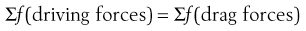 (12.1)
that is:
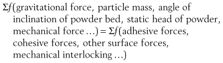 (12.2)
Some of these forces are modified or controlled by external factors related to particle properties, such as size, shape and density.
Particle size effects
Because adhesion and cohesion are phenomena that occur at surfaces, particle size will influence the flowability of a powder. In general, fine particles with very high surface-to-mass ratios are more adhesive/cohesive than coarser particles which are influenced more by gravitational forces. Particles larger than 250 µm are usually relatively free flowing but as the size falls below 100 µm, powders become more adhesive/cohesive and flow problems are likely to occur. Powders having a particle size less than 10 µm are usually extremely adhesive/cohesive and resist flow under gravity. An important exception to this reduction in flowability is when the very small particles become adhered/cohered to larger ones and the flowability of the powder as a whole then become controlled by the larger particles. This phenomenon is important in the concept of ordered mixing (Chapter 11) and formulation of dry powder inhalers (Chapter 37).
Particle shape
Powders with similar particle sizes but dissimilar shapes can have markedly different flow properties owing to differences in interparticulate contact areas. For example, a group of spheres has minimum interparticulate contact and generally optimal flow properties, whereas a group of particle flakes or dendritic particles has a very high surface-to-volume ratio and poorer flow properties. Irregular shaped particles may experience mechanical interlocking in addition to adhesional and cohesional forces.
Particle density (true density)
Because powders normally flow under the influence of gravity, higher density particles are generally less adhesive/cohesive than less dense particles of the same size and shape.
Packing geometry
A set of particles can be filled into a volume of space to produce a powder bed which is in static equilibrium owing to the interaction of gravitational and adhesive/cohesive forces. By slight vibration of the bed, particles can be mobilized so that if the vibration is stopped, the bed is once more in static equilibrium but occupies a different spatial volume than before. The change in bulk volume has been produced by rearrangement of the packing geometry of the particles. In general, such geometric rearrangements result in a transition from loosely packed particles to more tightly packed ones, so that the equilibrium balance moves from left to right in Equations 12.1 and 12.2 and adhesion/cohesion increases. This also means that more tightly packed powders require a higher driving force to produce powder flow than more loosely packed particles of the same powder.
Characterization of packing geometry by porosity and bulk density
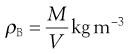
A set of monosized spherical particles can be arranged in many different geometric configurations. At one extreme, when the spheres form a cubic arrangement, the particles are most loosely packed and have a porosity of 48% (Fig. 12.2a). At the other extreme, when the spheres form a rhombohedral arrangement, they are most densely packed and have a porosity of only 26% (Fig. 12.2b). The porosity used to characterize packing geometry is linked to the bulk density of the powder. Bulk density, ρB, is a characteristic of a powder rather than individual particles and is given by the mass, M, of powder occupying a known volume, V, according to the relationship:
 (12.3)
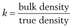
The bulk density of a powder is always less than the true density of its component particles because the powder contains intraparticular pores or interparticulate air-filled voids. Thus whereas a powder can only possess a single true density, it can have many different bulk densities, depending on the way in which the particles are packed and the bed porosity. However, a high bulk density value does not necessarily imply a close-packed low-porosity bed, as bulk density is directly proportional to true density.
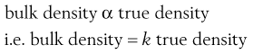 (12.4)
or:
 (12.5)
The constant of proportionality, k, is known as the packing fraction or fractional solids content. For example, the packing fraction for dense, randomly packed spheres is approximately 0.65, whereas the packing fraction for a set of dense, randomly packed discs is 0.83. Also:
 (12.6)
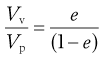
where e is the fractional voidage of the powder bed, which is usually expressed as a percentage and termed the bed porosity. Another way of expressing fractional voidage is to use the ratio of particle volume Vp to bulk powder volume VB, i.e.:
 (12.7)
A simple ratio of void volume Vv to particle volume Vp represents the voids ratio:
 (12.8)
which provides information about the stability of the powder mass.
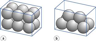
Fig. 12.2 Different geometric packings of spherical particles, (a) Cubic packing. (b) Rhombohedral packing.
For powders having comparable true densities, an increase in bulk density causes a decrease in porosity. This increases the number of interparticulate contacts and contact areas and causes an increase in adhesion/cohesion. For very coarse particles, this may still be insufficient to overcome the gravitational influence on particles. Conversely, a decrease in bulk density may be associated with a reduction in particle size and produce a loose-packed powder bed which, although porous, is unlikely to flow because of the inherent adhesiveness/cohesiveness of the fine particles.
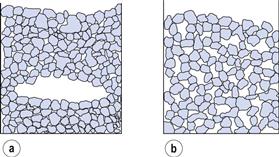
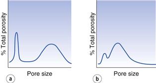
In powders where the particle shape or cohesiveness promotes arch or bridge formation, two equilibrium states could have similar porosities but widely different packing geometries. In such conditions, interparticulate pore size distributions can be useful for comparing packing geometry.
For example, Figure 12.3a shows a group of particles in which arching has occurred and Figure 12.3b shows a similar group of particles in which arch formation is absent. The total porosity of the two systems can be seen to be similar but the pore size distributions (Fig. 12.4) reveal that the powder in which arch formation has occurred is generally more tightly packed than that in which arching is absent.
The measurement of packing geometry by an assessment of percentage compressibility and changes in bulk density have proved to be useful indirect methods to estimate powder flow in an industrial manufacturing process (see later in this chapter).
Process conditions: hopper design
Flow through an orifice
There are many examples of this type of flow to be found in the manufacture of pharmaceutical solid dosage forms, for example when granules or powders flow through the opening in a hopper or bin used to feed powder to tableting machines, capsule-filling machines or sachet-filling machines. Because of the importance of such flow in producing unit doses containing the same or very similar powder masses, and the importance of flow behaviour in other industries, the behaviour of particles being fed through orifices has been extensively studied. This has led to the design of hopper now used in most industrial pharmaceutical powder applications.
A hopper or bin can be modelled as a tall cylindrical container having a closed orifice in the base and initially full of a free-flowing powder which has a horizontal upper surface (Fig. 12.5a). When the orifice at the base of the container is opened, flow patterns develop as the powder discharges (Fig. 12.5a–f).
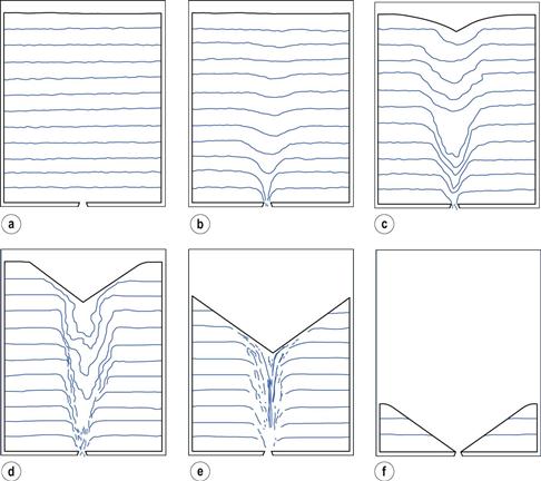
The observed sequence is as follows:
1. On opening the orifice, there is no instantaneous movement at the surface but particles just above the orifice fall freely through it (Fig. 12.5b).
2. A depression forms at the upper surface and spreads outwards to the sides of the hopper (Fig. 12.5c, d).
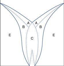
3. Provided that the container is tall and not too narrow, the flow pattern illustrated in Figure 12.5e and shown schematically in Figure 12.6 is rapidly established. Particles in zone A move rapidly over the slower moving particles in zone B, whereas those in zone E remain stationary. The particles in zone A feed into zone C, where they move quickly downwards and out through the orifice. The more slowly moving particles in zone B do not enter zone C.
Important practical consequences of this flow pattern are that if a square-bottomed hopper or bin is repeatedly refilled and partially emptied, the particles in a zone towards the base and sides of the container (Fig. 12.5f) will not be discharged and may eventually degrade. Alternatively, this static zone may provide a segregation potential for previously homogeneous powders. Thus process hoppers are designed to have a conical lower section, in effect eliminating zone E in Figure 12.6.
Factors affecting flow rates through orifices
The flow patterns described above, together with powder flow rates through orifices, are dependent on many different factors, some of which are particle related and some process related. Particle-related effects, notably particle size, are discussed above. Process-related effects include the following.
Orifice diameter.
The rate of powder flow through an orifice is proportional to a function of orifice diameter, DO. Flow rate is directly proportional to DOA, where A is a constant with a value of approximately 2.6. Provided that the height of the powder bed, called the head of powder, remains considerably greater than the orifice diameter, flow rate is virtually independent of powder head. This situation is unlike that relating to liquid flow through an orifice, where the flow rate falls off continuously as the head diminishes. The constant rate of flow for powders is a useful property as it means that if a bulk powder is filled into dies, sachets, capsules or other enclosures, they will receive equal weights if filled for equal times.
Hopper width, height of powder in the hopper and hopper wall angle also influence the rate of discharge of powder or granules from a hopper.
Characterization of powder flow
When examining the flow properties of a powder, it is useful to be able to quantify the type of behaviour in terms of speed and (possibly more importantly) uniformity of flow. Many different methods are available, either directly, using dynamic or kinetic methods, or indirectly, generally by measurements carried out on static beds. These tests attempt to correlate the various measures of powder flow to manufacturing properties. A wide range of equipment is available to cater for the wide range of powder types and particle sizes encountered in pharmaceutical applications.
The apparatus and techniques described below are illustrative of the principles on which most equipment is based. It is well established that no single, simple test will truly characterize the flow properties during large-scale manufacture but, with careful control, the tests can give a good estimate. This is particularly useful in the early stages of preformulation, formulation and scale up.
In general, methods of measuring powder flow must be practical, useful, reproducible and sensitive, and must yield meaningful results. An appropriate strategy is to use multiple standardized test methods to characterize the various aspects of powder flow that need to be understood by the pharmaceutical scientist. Pharmacopoeias are making an effort to standardize the tests used to assess powder flow and current tests that have an indicated preference are i) angle of repose, ii) compressibility index and Hausner ratio, iii) flow rate through an orifice and iv) shear cell. Each of these is described in the text below.
Indirect methods
Measurement of cohesive/adhesive properties
Adhesive or cohesive forces (acting between particles of different substances or between particles of the same substance, respectively) can, in practice, be determined by studying the adhesion/cohesion characteristics of a bed of powder. This avoids delicate and difficult experimentation to determine the attractive forces between, say, two individual particles.
Shear strength
Shear stress.
This can be defined as the stress (force per unit area) necessary to shear a powder bed under conditions of zero normal load. Using this criterion, the shear strength of a powder can be determined from the resistance to flow caused by adhesion, cohesion or friction and can be measured using a shear cell.
The shear cell (Fig. 12.7) is a relatively simple piece of apparatus which is designed to measure shear stress, τ, at different values of normal stress, σ. There are several types of shear cell which use different methods of applying the stresses and measuring the shear strengths. The most common being based on the original Jenike principle. In order to carry out a shear stress determination, powder is packed into the two halves of the cell and a normal stress is applied to the lid of the assembled cell. A shearing stress across the two halves of the cell is applied and the shear stress is determined by dividing the shear force by the cross-sectional area of the powder bed. The measured shear stress will increase as the normal stress is increased. Shear cell experiments are rather time-consuming and require a well-trained operator.
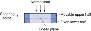
In order to calculate the cohesion in a powder bed using the shear cell method, the shear stress is plotted against normal stress and extrapolated back to zero normal stress, as the shear stress at zero normal stress is, by definition, equal to the cohesion of the powder. The higher the intercept the greater are the adhesive/cohesive forces. For a completely non-cohesive powder, the extrapolated shear stress will pass through the origin, equivalent to zero shear stress.
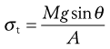
Tensile strength
The tensile strength of a powder bed is also a characteristic of the internal friction, adhesion or cohesion of the particles. In tensile strength determinations, the powder bed is caused to fail in tension by splitting, rather than failing in shear by sliding, as is the case with shear stress determinations. The powder is packed into a split plate, one half of which is fixed and the other half free to move (Fig. 12.8). The table is then tilted towards the vertical until the angle is reached at which the powder cohesion is overcome and the mobile half-plate breaks away from the static half-plate. The tensile strength, σt, of the powder can then be determined from Equation 12.8:
 (12.9)
where M is the mass of the mobile half-plate plus powder, θ the angle of the tilted table to the horizontal at the point of failure and A is the cross-sectional area of the powder bed.
The tensile strength values of different powders have been found to correlate reasonably well with another measurement of powder flowability – angle of repose.
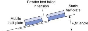
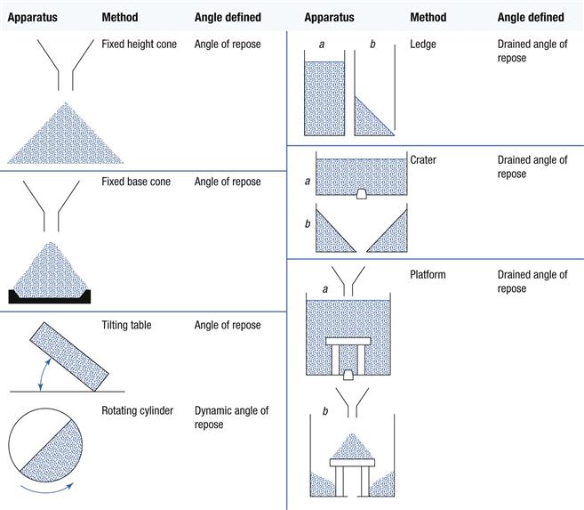
Angle of repose
Angles of repose have been used as indirect methods of quantifying powder flowability, because of their relationship with interparticulate cohesion. There are many different methods of determining angles of repose and some of these are shown in Table 12.1. The different methods may produce different values for the same powder, although these may be self-consistent. It is also possible that different angles of repose could be obtained for the same powder, owing to differences in the way the samples were handled prior to measurement. For these reasons, angles of repose tend to be variable and are not always representative of flow under specific conditions.
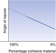
It is particularly difficult to determine this angle with very poor flowing material (see discussion of Fig. 12.1). In order to overcome this problem, it is suggested that determinations of angles of repose be carried out using different concentrations of a very adhesive/cohesive powder and a non-adhesive/cohesive powder. The angles of repose are plotted against mixture concentration and extrapolated to 100% of the more adhesive/cohesive powder content so as to obtain the appropriate angle of repose that would be unobtainable in practice (Fig. 12.9).
As a general guide, powders with angles of repose greater than 45° have unsatisfactory flow properties, whereas minimum angles close to 25° will have excellent flow properties. A more detailed correlation was suggested by Carr. This is shown in Table 12.2.
Table 12.2
Angle of repose as an indication of powder flow properties (based on Carr)
| Angle of repose (degrees) | Type of flow |
| 25–30 | Excellent |
| 31–35 | Good |
| 36–40 | Fair (flow aid not needed) |
| 41–45 | Passable (may hang up, flow aid might be needed) |
| 46–55 | Poor (agitation or vibration needed) |
| 56–65 | Very poor |
| Over 66 | Very, very poor |
Determinations based on bulk density
Bulk density measurements
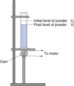
The bulk density of a powder is dependent on particle packing and changes as the powder consolidates. A consolidated powder is likely to have a greater arch strength than a less consolidated one and may therefore be more resistant to powder flow. The ease with which a powder consolidates can be used as an indirect method of quantifying powder flow.
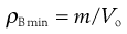
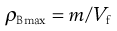
Figure 12.10 shows a mechanical tapping device or jolting volumeter which can be used to follow the change in packing volume that occurs when void space diminishes and consolidation occurs. The powder contained in the measuring cylinder is mechanically tapped by means of a constant velocity rotating cam. The volume decreases from its original state (Vo) to a final state (Vf). Initial bulk density ρBmin (also known as fluff or poured bulk density) and a final bulk density ρBmax (also known as equilibrium, tapped or consolidated bulk density when it has attained its most stable, i.e. unchanging, arrangement) are calculated from the mass (m) and bulk volume of the powder (Eqns 12.10 and 12.11).
 (12.10)
 (12.11)
In recent years, the popularity and perceived usefulness of flowability tests based on bulk density has increased. The two most useful and best characterized are Hausner ratio and compressibility index.
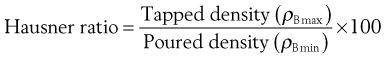
Hausner ratio
Hausner found that the ratio ρBmax/ρBmin (or the ratio Vo/Vf, which is quantitatively identical) was related to interparticulate friction. Because of this, he was able to demonstrate that the following ratio was predictive of powder flow.
 (12.12)
He showed that powders with low interparticulate friction, such as coarse spheres, had ratios of less than 1.2, whereas more cohesive, less free-flowing powders such as flakes have Hausner ratios greater than 1.5.
Carr’s index (Compressibility index)
Another indirect method of measuring powder flow from bulk densities was developed by Carr. The percentage compressibility of a powder (Carr’s Index) is a direct measure of the potential powder arch or bridge strength and stability and is calculated according to Equation 12.13:
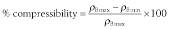 (12.13)
Table 12.3 shows the generalized relationship between descriptions of powder flow and percent compressibility according to Carr. The table also includes the equivalent Hausner ratios.
Table 12.3
Relationship between powder flowability, % compressibility and Hausner ratio
| Compressibility index (%) (Carr’s index) |
Type of flow | Hausner ratio |
| 1–10 | Excellent | 1.00–1.11 |
| 11–15 | Good | 1.12–1.18 |
| 16–20 | Fair | 1.19–1.25 |
| 21–25 | Passable | 1.26–1.34 |
| 26–31 | Poor | 1.35–1.45 |
| 32–37 | Very poor | 1.46–1.59 |
| >38 | Very, very poor | >1.60 |
Critical orifice diameter
Critical orifice diameter is a measure of powder cohesion and arch strength. In order to carry out measurements of critical orifice diameter, powder is filled into a shallow tray to a uniform depth with near-uniform packing. The base of the tray is perforated with a graduated series of holes, which are blocked either by resting the tray on a plane surface or by the presence of a simple shutter. The critical orifice diameter is the size of the smallest hole through which powder discharges when the tray is lifted or the shutter removed. Sometimes repetition of the experiment produces a range of values for critical orifice diameter; in these cases maximum and minimum values are sometimes quoted.
An alternative critical orifice method for determining powder flowability uses a cylinder with a series of interchangeable base plate discs having different diameter orifices. Flow rate through a particular orifice size can be used as a simple standard to specify materials for use in filling given capsule sizes, sachets or producing particular tablet sizes at a specified rate.
Direct measurements of flow
Hopper flow rate
A simple direct method of determining powder flowability is to measure the rate at which powder discharges from a hopper. A simple shutter is placed over the hopper outlet and the hopper is filled with powder. The shutter is then removed and the time taken for the powder to discharge completely is recorded. By dividing the discharged powder mass by this time, a mass flow rate is obtained which can be used for quantitative comparison of different powders.
Hopper or discharge tube outlets should be selected to provide a good model for a particular flow application. For example, if a powder discharges well from a hopper into a tablet machine feed frame but does not flow reproducibly into the tablet die, then it is likely that more useful information will be generated by selecting experimental conditions to model those occurring in flow from the feeder to the die, rather than those in flow from the hopper to the feeder.
Recording flowmeter
A recording flowmeter is essentially similar to the method described above except that powder is allowed to discharge from a hopper or container onto a balance. The digital signal from the balance records the increase in powder mass with time. Recording flowmeters allow mass flow rates to be determined and also provide a means of quantifying uniformity of flow.
Improvement of powder flowability
Alteration of particle size and size distribution
Because coarse (largest) particles are generally less cohesive than fine (smaller) particles and an optimum size for free flow exists, there is a distinct processing disadvantage in using a finer grade of powder than is necessary.
The size distribution can also be altered to improve flowability by removing a proportion of the fine particle fraction or by increasing the proportion of coarser particles, such as may be achieved through granulation.
Alteration of particle shape or texture
In general, for a given particle size, more spherical particles have better flow properties than more irregular particles. The process of spray-drying can be used to produce near-spherical excipients, for example spray-dried lactose. Under certain circumstances, drug particles that are normally acicular (needle-shaped) can be made more spherical by spray-drying or by temperature-cycling crystallization.
The surface texture of particles may also influence powder flowability, as particles with very rough surfaces will have a greater tendency to interlock than smooth-surfaced particles. The shape and texture of particles can also be altered by control of production methods, such as crystallization conditions.
Alteration of surface forces
Reduction of electrostatic charges can improve powder flowability and this can be achieved by altering process conditions to reduce frictional contacts. For example, where powder is poured down chutes or conveyed along pipes pneumatically, the speed and length of transportation should be minimized. Electrostatic charges in powder containers can be prevented or discharged by efficient earth connections.
The moisture content of particles is also of importance to powder flowability, as adsorbed surface moisture films tend to increase bulk density and reduce porosity. In cases where moisture content is excessive, powders should be dried and, if hygroscopic, stored and processed under low-humidity conditions.
Formulation additives: flow activators
Flow activators are commonly referred to pharmaceutically as ‘glidants’, although some also have lubricant or antiadherent properties. Flow activators improve the flowability of powders by reducing adhesion and cohesion.
A flow activator with an exceptionally high specific surface area is colloidal silicon dioxide, which may act by reducing the bulk density of tightly packed powders. Colloidal silicon dioxide also improves flowability of formulations, even those containing other glidants, although if used excessively it can cause flooding.
Where powder flowability is impaired through increased moisture content, a small proportion of very fine magnesium oxide may be used as a flow activator. Used in this way, magnesium oxide appears to disrupt the continuous film of adsorbed water surrounding the moist particles.
The use of silicone-treated powder, such as silicone-coated talc or sodium bicarbonate, may also be beneficial in improving the flowability of moist or hygroscopic powder.
Alteration of process conditions
Use of vibration-assisted hoppers
In cases where the powder arch strength within a bin or hopper is greater than the stresses in it due to gravitational effects, powder flow will be interrupted or prevented. If the hopper cannot be redesigned to provide adequate downward stresses and if the physical properties of the particles cannot be adjusted or the formulation altered, then extreme measures are required. One method of encouraging powder flow where arching or bridging has occurred within a hopper is to add to the flow-inducing stresses by vibrating the hopper mechanically. Both the amplitude and the frequency of vibration can be altered to produce the desired effect. This may vary from a single cycle or shock, produced by a compressed-air device or hammer, to continuous high frequencies produced, for example, by out-of-balance electric motors mounted on a hopper frame.
Use of force feeders
The flow of powders that discharge irregularly or flood out of hoppers can be improved by fitting vibrating baffles at the base of the conical section within a hopper.
The outflowing stream from a hopper can be encouraged to move towards its required location using a slightly sloping moving belt or, in the case of some tableting machines, the use of mechanical force feeders. Force feeders are usually made up of a single or two counter-rotating paddles at the base of the hopper just above the die table in place of a feed frame. The paddles act by preventing powder arching over dies and thereby improve die filling, especially at high turret speeds.
Summary
In most pharmaceutical technology operations, it is difficult to alter one process without adversely influencing another. In the case of alterations made in order to improve powder flow, relative particle motion will be promoted but this could lead to demixing or segregation. In extreme cases, improving powder flow to improve weight uniformity may reduce content uniformity through increased segregation.
Bibliography
1. Banker GS, Rhodes CT. Modern Pharmaceutics. 4th edn New York: Marcel Dekker; 2002.
2. Gotoh K, Masuda H, Higashitan K. Powder Technology Handbook. 2nd edn New York: Marcel Dekker; 1997.
3. Lieberman H. Pharmaceutical Dosage Forms: Disperse Systems. vol. 2 2nd edn New York: Marcel Dekker; 1996.
4. Lieberman H. Pharmaceutical Dosage Forms: Disperse Systems. vol. 3 2nd edn New York: Marcel Dekker; 1998.
5. Lieberman H, Lachman L, Schwartz JB. Pharmaceutical Dosage Forms: Tablets. vol. 2 2nd edn New York: Marcel Dekker; 1990.
6. McNaughton K, ed. Solids Handling. New York: McGraw-Hill; 1981.
7. Niazi SK, ed. Handbook of Pharmaceutical Manufacturing Formulations: vol 2 Uncompressed Solid Products, Part V Powder Flow Properties. Boca Raton, Florida: CRC Press; 2004.
8. Rhodes M. Principles of Powder Technology. Chichester: John Wiley; 1990.
9. Handbook of Powder Technology. vol. 11. Salmon AD, Hounslow MJ, Seville JPK, eds. 1st edn Amsterdam: Elsevier; 2007.
10. Advances in the Mechanics and the Flow of Granular Materials. vols 1 and 2. Shahinpoor M, ed. Houston: Gulf Publishing; 1983.
11. Swarbrick J, Boylan JC. Encyclopedia of Pharmaceutical Technology. New York: Marcel Dekker; 2002.
[/level-membership-for-basic-science-category][not-level-membership-for-basic-science-category]
Powder flow
Michael E. Aulton
Chapter contents
Particle properties and bulk flow
Process conditions: hopper design
Characterization of powder flow
Determinations based on bulk density
Improvement of powder flowability
Alteration of particle size and size distribution
Alteration of particle shape or texture
Formulation additives: flow activators
Key points
Introduction
Powders are generally considered to be composed of solid particles of the same or different chemical compositions having equivalent diameters less than 1000 µm. Granules are groups of particles formed into granules and individual larger particles which may have overall dimensions greater than 1000 µm (Chapter 28). As far as powder flow is concerned, these will be discussed together and the word ‘powder’ is used here to describe either system.
The largest pharmaceutical use of powders is to produce tablets and capsules. Together with mixing and compaction properties, the flowability of a powder is of critical importance in the production of pharmaceutical dosage forms. Some of the reasons for producing free-flowing pharmaceutical powders include:
There are many industrial processes that require powders to be moved from one location to another and this is achieved by many different methods, such as gravity feeding, mechanically assisted feeding, pneumatic transfer, fluidization in gases and liquids and hydraulic transfer. In each of these examples, powders are required to flow and, as with other operations described earlier, the efficiency with which they do so is dependent on both process design and particle properties.
Particle properties
Adhesion and cohesion
The presence of molecular forces produces a tendency for solid particles to stick to themselves and to other surfaces. Adhesion and cohesion can be considered as two aspects of the same phenomenon. Cohesion occurs between like surfaces, such as the same component particles in a bulk solid, whereas adhesion occurs between two different objects, for example between two different particles, or between a particle and, say, a hopper wall.
Adhesive and cohesive forces acting between particles in a powder bed are composed mainly from short-range non-specific van der Waals forces which increase as particle size decreases and vary with changes in relative humidity. Other attractive forces contributing to interparticulate adhesion and cohesion may be produced by surface tensional forces between adsorbed liquid layers at the particle surfaces and by electrostatic forces arising from contact or frictional charging. These may have short duration but increase adhesion and cohesion through improving interparticulate contacts and hence increasing the quantity of van der Waals interactions. Cohesion provides a useful method of characterizing the drag or frictional forces acting within a powder bed to prevent powder flow.
Angle of repose
Angle of repose is a simple measure of powder flow but it is based on scientific principles. An object, such as a particle, will begin to slide when the angle of inclination is large enough to overcome frictional forces. Conversely, an object in motion will stop sliding when the angle of inclination is below that required to overcome adhesion/cohesion. This balance of forces causes a powder poured from a container on to a horizontal surface to form a heap. Initially the particles stack until the approach angle for subsequent particles joining the stack is large enough to overcome friction. They then slip and roll over each other until the gravitational forces balance the interparticulate forces. The sides of the heap formed in this way make an angle with the horizontal which is called the angle of repose and is a characteristic of the internal friction or cohesion of the particles.
The value of the angle of repose will be high if a powder is cohesive and low if a powder is non-cohesive. If the powder is very cohesive, the heap may be characterized by more than one angle of repose. Initially, the interparticulate cohesion causes a very steep cone to form but, on the addition of further powder, this tall stack may suddenly collapse, causing air to be entrained between particles and partially fluidizing the bed, thus making it more mobile. The resulting heap has two angles of repose: a large angle remaining from the initial heap and a shallower angle formed by the powder flooding from the initial heap (Fig. 12.1).
Particle properties and bulk flow
In the discussion concerning adhesion/cohesion it is clear that an equilibrium exists between forces responsible for promoting powder flow and those preventing powder flow, i.e. at equilibrium:
(12.1)
that is:
(12.2)
Some of these forces are modified or controlled by external factors related to particle properties, such as size, shape and density.
Particle size effects
Because adhesion and cohesion are phenomena that occur at surfaces, particle size will influence the flowability of a powder. In general, fine particles with very high surface-to-mass ratios are more adhesive/cohesive than coarser particles which are influenced more by gravitational forces. Particles larger than 250 µm are usually relatively free flowing but as the size falls below 100 µm, powders become more adhesive/cohesive and flow problems are likely to occur. Powders having a particle size less than 10 µm are usually extremely adhesive/cohesive and resist flow under gravity. An important exception to this reduction in flowability is when the very small particles become adhered/cohered to larger ones and the flowability of the powder as a whole then become controlled by the larger particles. This phenomenon is important in the concept of ordered mixing (Chapter 11) and formulation of dry powder inhalers (Chapter 37).
Particle shape
Powders with similar particle sizes but dissimilar shapes can have markedly different flow properties owing to differences in interparticulate contact areas. For example, a group of spheres has minimum interparticulate contact and generally optimal flow properties, whereas a group of particle flakes or dendritic particles has a very high surface-to-volume ratio and poorer flow properties. Irregular shaped particles may experience mechanical interlocking in addition to adhesional and cohesional forces.
Particle density (true density)
Because powders normally flow under the influence of gravity, higher density particles are generally less adhesive/cohesive than less dense particles of the same size and shape.
Packing geometry
A set of particles can be filled into a volume of space to produce a powder bed which is in static equilibrium owing to the interaction of gravitational and adhesive/cohesive forces. By slight vibration of the bed, particles can be mobilized so that if the vibration is stopped, the bed is once more in static equilibrium but occupies a different spatial volume than before. The change in bulk volume has been produced by rearrangement of the packing geometry of the particles. In general, such geometric rearrangements result in a transition from loosely packed particles to more tightly packed ones, so that the equilibrium balance moves from left to right in Equations 12.1 and 12.2 and adhesion/cohesion increases. This also means that more tightly packed powders require a higher driving force to produce powder flow than more loosely packed particles of the same powder.
Characterization of packing geometry by porosity and bulk density
A set of monosized spherical particles can be arranged in many different geometric configurations. At one extreme, when the spheres form a cubic arrangement, the particles are most loosely packed and have a porosity of 48% (Fig. 12.2a). At the other extreme, when the spheres form a rhombohedral arrangement, they are most densely packed and have a porosity of only 26% (Fig. 12.2b). The porosity used to characterize packing geometry is linked to the bulk density of the powder. Bulk density, ρB, is a characteristic of a powder rather than individual particles and is given by the mass, M, of powder occupying a known volume, V, according to the relationship:
(12.3)
The bulk density of a powder is always less than the true density of its component particles because the powder contains intraparticular pores or interparticulate air-filled voids. Thus whereas a powder can only possess a single true density, it can have many different bulk densities, depending on the way in which the particles are packed and the bed porosity. However, a high bulk density value does not necessarily imply a close-packed low-porosity bed, as bulk density is directly proportional to true density.
(12.4)
or:
(12.5)
The constant of proportionality, k, is known as the packing fraction or fractional solids content. For example, the packing fraction for dense, randomly packed spheres is approximately 0.65, whereas the packing fraction for a set of dense, randomly packed discs is 0.83. Also:
(12.6)
where e is the fractional voidage of the powder bed, which is usually expressed as a percentage and termed the bed porosity. Another way of expressing fractional voidage is to use the ratio of particle volume Vp to bulk powder volume VB, i.e.:
(12.7)
A simple ratio of void volume Vv
[/not-level-membership-for-basic-science-category]
