Chapter 33 Posterior Stabilization of Craniovertebral Junction
OCCIPITAL BONE WIRING
Contoured loops or rods connected with sublaminar wires or cables have been the mainstay of occipitocervical fixation. This procedure is performed through partial- or full-thickness trephines in the occipital bone, with bone graft alone or supplemented with loop/rod constructs.2
PROCEDURE

OCCIPITAL BONE SCREW FIXATION3
For occipital fixation, the plate and screws are introduced.
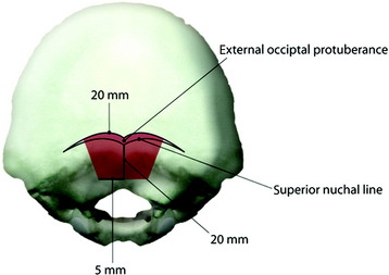
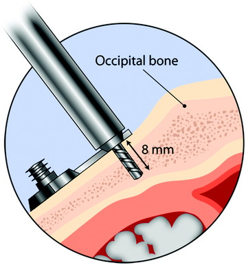
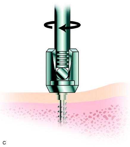
Occipital bone is thickest in the midline (10–18 mm, average 14 mm) and becomes thin as it goes to the peripheral area (Fig. 33-3). The best zone for screw insertion is up to 20 mm lateral to the external occipital protuberance (EOP) along the superior nuchal line decreasing to 5 mm lateral to the EOP at 20 mm inferior to the superior nuchal line. The plate should lie flush with the occipital bone. The screws are inserted through the holes that are made in the plates. After the plate is fit to the occipital bone surface, the pilot hole is made in the occiput with a 3.5-mm drill bit. The depth of drilling is determined by the examination of the radiographs. With a computed tomography (CT) scan, the correct thickness of the occipital bone can be measured at the purchase site. A depth gauge is used to check the depth drilled. Then the occipital screw is placed in a self-retaining screwdriver. The screw depth is usually 8 mm (Fig. 33-4). For the occipital screw, bicortical purchase provides better stability than unicortical purchase. However, bicortical purchase carries the risk of damaging the underlying structures (i.e., cerebellar or venous sinus injury). A recent biomechanical study showed that unicortical fixation at the midline ridge approached the pullout strength of bicortical fixation at other anatomical locations in the occiput.4 This fixation method shows an improved biomechanical profile compared with wiring.5 The number of the lower cervical vertebrae to be fixed to gain sufficient stability can be reduced with screw fixation.
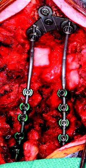
There are several kinds of plates: horseshoe-shaped, Y-shaped, and T-shaped. A horseshoe-shaped plate with three occipital screws is connected to the C1, C2 transarticular screw (Figs. 33-5 and 33-6). The T-shaped plate is attached firmly to occipital bone surface (Figs. 33-7 and 33-8). This construct shows bilateral rods connected at the occiput by a plate with large-bore cortical screws in the midline. It is mechanically advantageous to include as many fixation points as possible when atlantoaxial instability is treated surgically.6
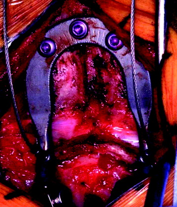
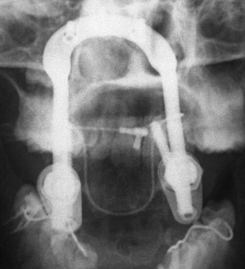
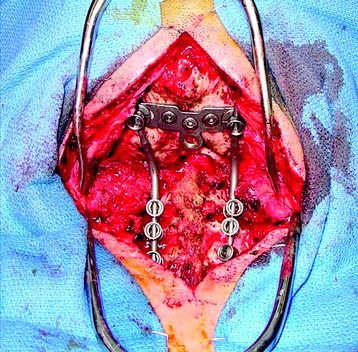
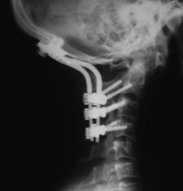
Fig. 33-8 The rod is connected from the occipital screw to the C1 lateral mass and the C2 pedicle screw.
C1 LATERAL MASS SCREW
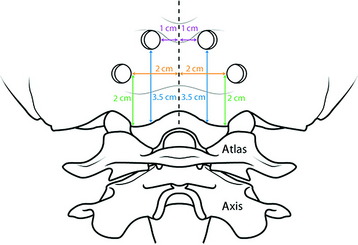
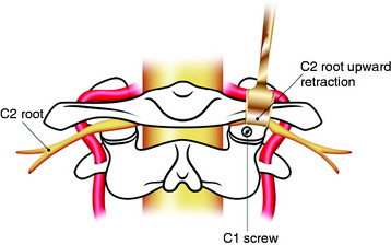
According to others’ data,7 the mean height and width for screw entry on the posterior surface of the lateral mass are 3.9 mm and 7.3 mm, respectively. The ideal point of entry is just below the C1 posterior arch and on the middle point of the lateral mass (Fig. 33-9). Medial angulation ranged from 25 to 45 degrees. The length of the screw for bicortical purchase is from 14.4–22.5 mm. The length and medial angulation degree can be measured with a preoperative CT scan (Fig. 33-10). The superiorly directed angle can be varied from 0–30 degrees.
C2 PEDICLE SCREW
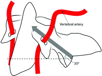
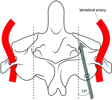
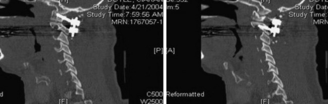
The entry point of the C2 screw is the superomedial portion of the C2 lateral mass. The direction of the screw is roughly 15 degrees toward the midline and 35 degrees superiorly into the bony isthmus (Figs. 33-11 and 33-12). Postoperative lateral view shows that the anterior margin of the screw nearly reaches the anterior cortex of the C2 body (Figs. 33-13 and 33-14).
Medial angulation of the C1 lateral mass screw and the C2 pedicle screw is nearly the same. With respect to the sagittal angulation, the C1 lateral mass screw shows a slightly higher angle (Figs. 33-15 and 33-16). The C1 lateral mass screw has a wider configuration than the C2 pedicle screw (see Fig. 33-15). The C1 lateral mass–C2 pedicle screw technique seems to be safer than C1–2 transarticular screw fixation with respect to vertebral artery injury. No serious complications caused by vertebral artery injury have been reported. The more perpendicular sagittal angle of screw trajectory into the C1 lateral mass and C2 pedicle, compared with that in the transarticular technique, make this technique less likely to hit the vertebral artery.
ROD CONTOURING AND CONNECTION METHOD
Occipital Attachment
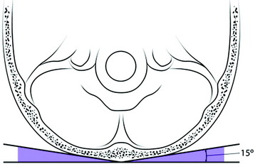
The plate should lie flush with the occiput. The occipital bone surface contours laterally with a 15-degree forward inclination (Fig. 33-17). For the complete attachment, the plate should be bent according to the inclination angle.
Alignment Of Occipitocervical Angle
After the occipital holes are made, a template is formed. A template is shaped such that its cranial end is adjacent to the midline, just reaching to the EOP (Fig. 33-18). The remainder of the template should pass over the lateral rims of the articular processes of the levels that are to be fused. The sagittal angle at the occipito-C1 junction is measured to be about 110 degrees.2 The occipital rod is shaped to the template.
Rod To Screw Connection
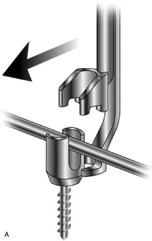
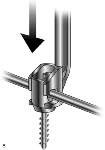
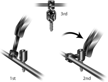
Sometimes the rod and screw connection may be difficult. The instrument for the adjustment of the rod into the screw head has been developed (Fig. 33-19). All the screws for use are polyaxial screws, which allow up to 55 degrees of angulation in one direction and up to 110 degrees of divergence. In cases of a difficult direct connection, a specially designed side connector can be used.
The connection between the laterally directed lateral mass screws and the medially directed pedicle screws often makes rod connection to adjacent fixation points difficult. The solution to this problem is the lateral offset connector (Fig. 33-20).
CASE ILLUSTRATION
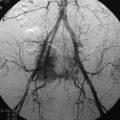
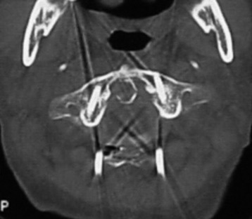
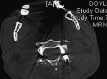
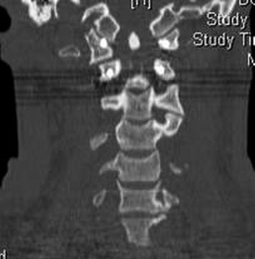
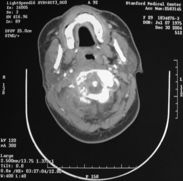
This case shows that a C1 lateral mass was destroyed by tumor metastasis on the right side (Fig. 33-22). The patient complained of severe neck pain, especially in rotation movement. The predental space measured 5 mm. Mild spinal cord compression was suspected, but myelopathic symptoms were not observed. The operation was performed with the aim of spinal stabilization without decompression. With extension position achieved, posterior instrumentation was performed. Occipital bone fixation was accomplished with plate and screw. At the C1 level, a lateral mass screw was fixed and a pedicle screw was purchased at C2 (Fig. 33-23). At C3, a lateral mass screw was used. All the screws were connected with the rods.
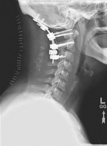
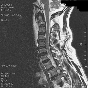
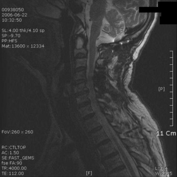
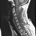
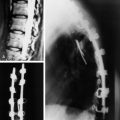
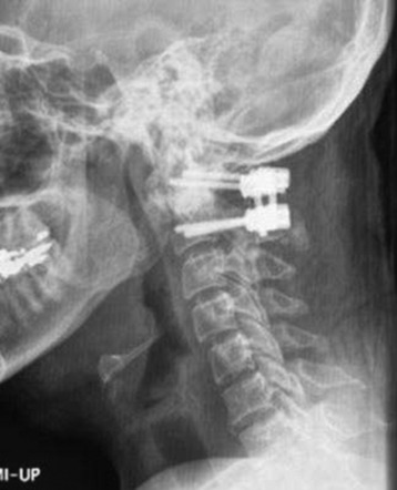
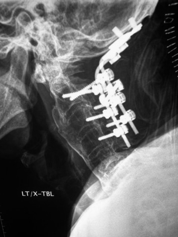
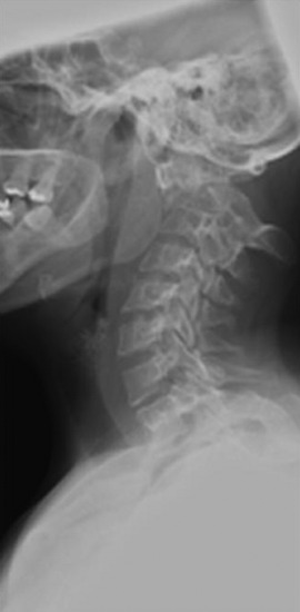
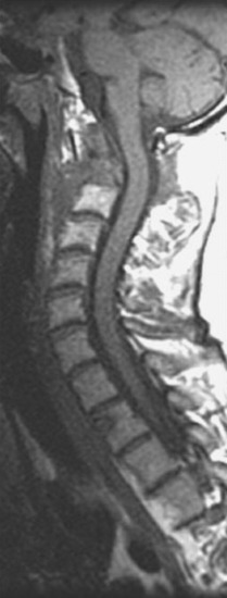
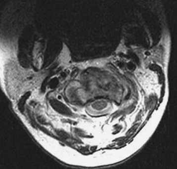
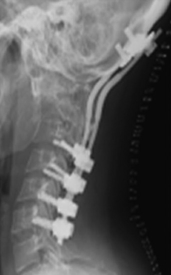
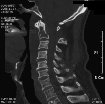
This patient presented with posterior neck pain with motion. With lateral x-ray, C2 dens could not be recognized easily. Cervical kyphosis measured 20 degrees (Fig. 33-24). Magnetic resonance imaging (MRI) showed that the mass was expanding to the anterior side and broke the anterior cortical margin. The posterior cortical margin was not bulging (Figs. 33-25 and 33-26). Ventral subarachnoid space was mildly effaced. The purpose of the operation was posterior stabilization without decompression. Occipital screws were used, and lateral mass screws were fixed onto the C3, C4, C5, and C6 levels (Fig. 33-27).
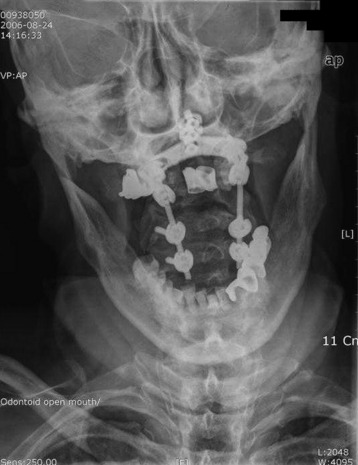
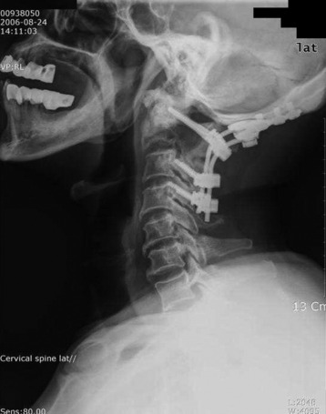
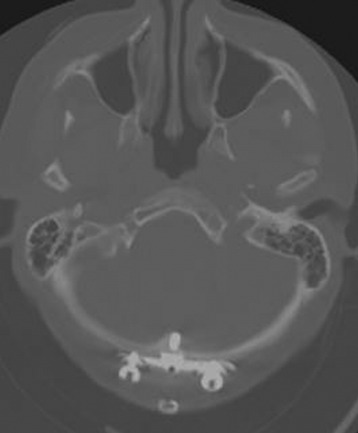
Postoperatively, the kyphotic angle was corrected to 5 degrees (Fig. 33-28). The occipital screws were seen to be located on the thickest portion of the occipital bone. The screws were confined within the inner cortex of the occipital bone (Fig. 33-29).
A 66-year-old man presented with severe posterior neck pain that was aggravated on sitting and standing posture. The pain radiated to the occipital area. He had no pain in either arm. CT and MRI were taken for a correct evaluation. CT showed that a low density mass filled the C2 body and destroyed the cortical continuity (Fig. 33-30).
MRI showed high signal mass on T2-weighted image (Fig. 33-31). Cord compression was not found. An operation was performed posteriorly. An occipital plate and screws were fixed on the occipital bone. At C1, C3, and C4, lateral mass screws were inserted. The screws were connected with a rod (Figs. 33-32 and 33-33). After posterior stabilization, CyberKnife radiosurgery was performed to the mass in the C2 body. Six months after radiosurgery was performed, follow-up MRI showed that the cortical discontinuity of the C2 body had been stabilized (Fig. 33-34).