[level-membership-for-neurosurgery-category]
Chapter 36 Posterior Stabilization in the Thoracic Spine
POSSIBLE OPTIONS IN THORACIC INSTRUMENTATION
Several posterior stabilization techniques have been used in patients with spinal tumors.1,2 Harrington distraction rods have long been used after resection of lesions of the thoracic and lumbar spine. But the Harrington three-point fixation system is likely to fail because of excessive bending loads when the anterior and middle vertebral columns are eroded by tumor. Segmental spinal fixation with a wire and rod system, introduced by Luque, provided more rigid fixation than the Harrington system. The major concerns associated with this system were complications related to the epidural passage of multiple sublaminar wires and limitations on the ability to resist axial forces. The hook system offered rigid segmental fixation and improved the ability to achieve spinal alignment in three dimensions. However, hook segmental fixation requires the presence of intact laminae and facets, and multiple motion segments above and below the level of tumor involvement should be fitted with the construct. The pedicle screw system provides the most rigid and stable construct, covering three columns with short segment application.3,4 Systems with increased stiffness and stability allow early mobilization without external immobilization. The rod hook/rod pedicle screw system has a stiffer construct compared with Luque rods or with wiring to Harrington rods.5
THORACIC WIRING
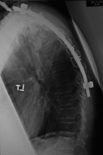
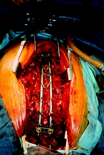
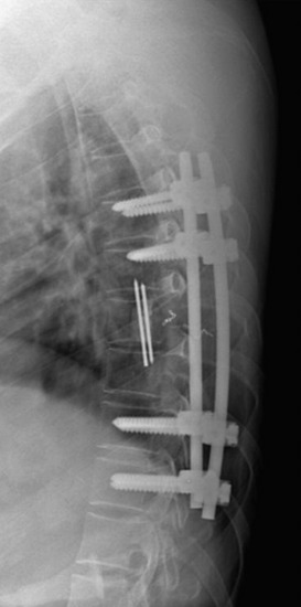
Sublaminar wires are often used in conjunction with the rods to provide rigid segmental stability to the posterior spine.6 Wire placement at the end of the instrumentation construct resists implant pullout in the sagittal plane (Fig. 36-1). The risk of bone/implant failure is lessened with this technique because of the multitude of points of fixation contact (Fig. 36-2).
TECHNIQUES OF WIRING
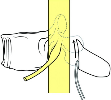
The radius of curvature of the bent sublaminar wire should be at least equal to the width of the lamina. The wires should be passed anterior to the lamina in a caudal to cranial direction and a lateral to medial direction. The tip of the wire should remain in contact with the undersurface of the lamina as it is advanced cranially (Fig. 36-3). The wire should be rolled so that the tip emerges at the upper end of the lamina in the midline. The looped leading edge can then be grasped with a nerve hook or narrow needle holder. The wire is then pulled through with a firm posterior force on the leading and trailing edge of the wire. The wire ends are bent to conform to the posterior lamina. Once the wire is passed, it should be twisted over the respective posterior lamina to prevent inadvertent canal migration.
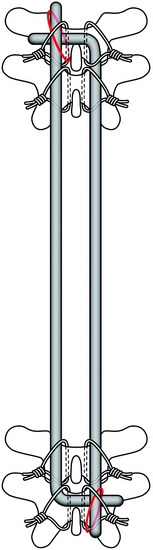
Harrington distraction rods with segmental wiring provide the best axial load stability. Luque segmental wiring, a semi-rigid fixation device, is best for rotational stability for burst fracture management (Fig. 36-4).7 The rod on each side of the midline is cut to the appropriate length and placed along the lamina. The wires are twisted around the rods. L-shaped rods are usually used. The L-shape aids in settling of the spine and prevents rod rotation. The L should be passed across the midline through an interspinous space and underneath the straight aspect of the opposing rod. This prevents the dorsal protrusion of the L-aspect of the rod. Wires are tightened down alternately, and double wires are recommended at the ends of the construct.
TRANSPEDICULAR SCREW FIXATION IN THORACIC SPINE
ANATOMY
There is no epidural space between the pedicle and dura.
The average distance between the pedicle and adjacent nerve root is known to be 1.9–4.1 mm superiorly and 1.5–3.2 mm inferiorly. There is a narrow safe zone (1–2 mm) between the pedicle and nerve root. Medial-lateral width of the pedicle is smaller than the superior-inferior diameter. The pedicle diameter decreases from the upper thoracic level to the middle thoracic level, then increases from the middle level to the lower level. The sagittal inclination decreases from T1 to T12.8 The medial inclination is greatest at the upper level, being straight at the middle and lower levels.
SURGICAL TECHNIQUES
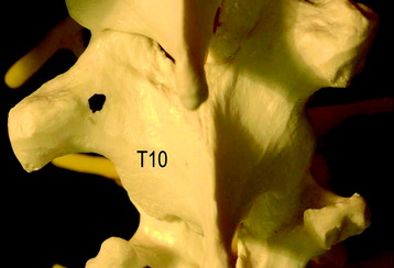
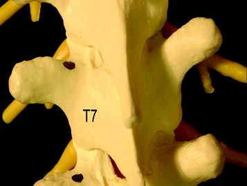
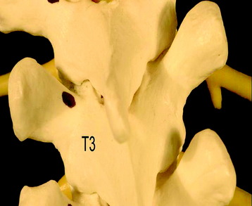
Starting Point (Entry Point)
The entry point varies according to the level of thoracic spine:
Insertion Technique: Funnel Technique4
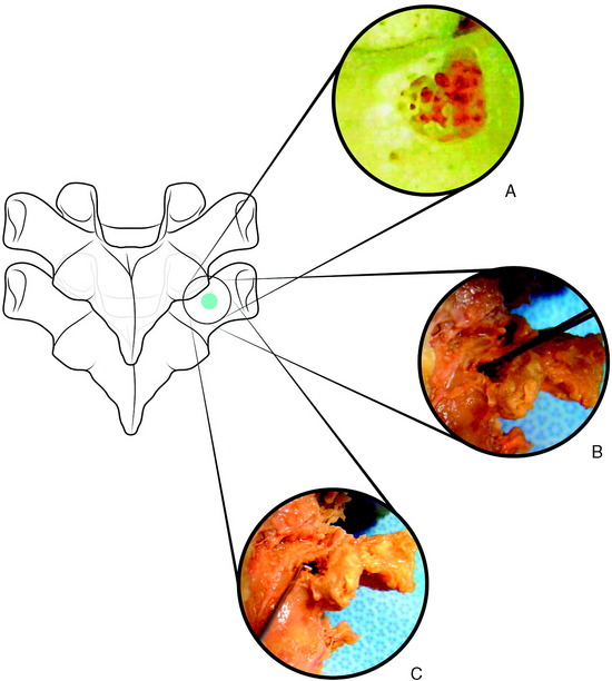
Funnel technique is a type of pedicle finding method that follows the cancellous bone space from the posterior cortex without the fluoroscopic guide. The anatomic characteristic of the thoracic pedicle demonstrates a thicker medial cortical wall compared with the lateral wall (Fig. 36-8).
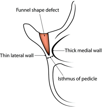
Fig. 36-8 Funnel-shaped cortical bone defect. The medial wall of the pedicle is thicker than the lateral wall.
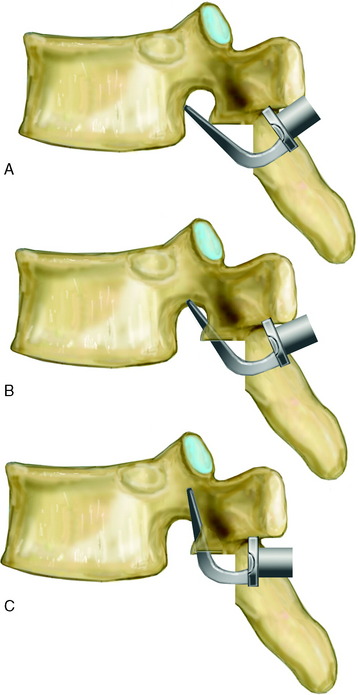
At the entry point, the posterior cortex overlying the top of the pedicle is removed by a rongeur. A 10-mm circle of cortical bone defect is created (Fig. 36-9, A). Compared with the lumbar spine, the pedicle entry point is more ventral. The cancellous bone is removed from the upper part of the pedicle with a small curette. A Kerrison rongeur is used to enlarge the cortical pedicle opening. Further removal of cancellous bone enlarges the pedicle funnel to the upper part of the pedicle isthmus. The inner cortical margins of the posterior part of the pedicle then form a funnel (see Fig. 36-8).
Careful probing of the pedicle isthmus is performed with a 2-mm pediatric pedicle probe, and then, if the pedicle inner diameter allows it, with the standard 4- to 5-mm pedicle probe (Fig. 36-9, B).
After successful probing, in operated patients, 55-mm-long Steinmann pins are placed into the hole as radiographic markers. An image intensifier is used to confirm their proper placement; the length of the pin is measured to determine screw length. The pedicle is tapped with a 5.5-mm tap. A right angle pedicle probe (“feeler”) is used to inspect the depth of the opening, as well as all four walls of the pedicle, for perforation (Fig. 36-9, C).
Insertion Technique: Free Hand Placement3
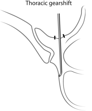
The thoracic gearshift (2-mm, blunt-tipped, slightly curved pedicle finder) is placed in the base of the pedicle and is used to search for a cancellous spot of the pedicle. The appropriate ventral pressure is applied to the thoracic gearshift probe. The gearshift is initially pointed laterally as a safety measure to prevent medial wall perforation (Fig. 36-10). The 2-mm tip goes down the cancellous portion of the pedicle.
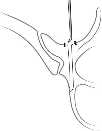
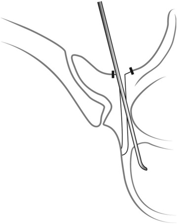
After the tip is inserted approximately 15–20 mm, the gearshift is removed and the tip is turned to face medially (Fig. 36-11). Before advancing the pedicle finder, the tip is placed carefully into the base of the hole. The path down the pedicle is then continued medially into the body with an ultimate depth averaging 30–40 mm for the lower thoracic region, 25–30 mm in the mid-thoracic region, and 20–25 mm for the proximal thoracic region in most adults (Fig. 36-12). The finder is rotated 180 degrees to make room for the screw after advancing the finder to the approximate length of the desired screw.
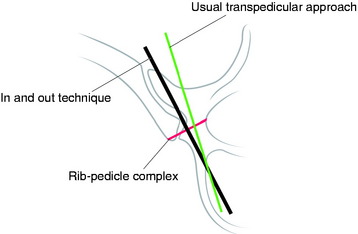
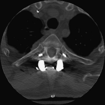
Extrapedicular Screw Placement (In-Out-In Technique)
When the pedicle diameter is very small, an alternative method of extrapedicular screw fixation within the pedicle rib unit can be attempted (Fig. 36-13). It was evaluated in a previous study and found to be anatomically feasible.9–11 The awl was placed just cephalad to the tip of the transverse process and advanced by hand between the transverse process and the rib. The direction of insertion was caudad in an oblique direction following the course of the rib medially to its articulation with the vertebral body. This was confirmed by fluoroscopic images in the anteroposterior (AP) plane. A depth gauge was then used to palpate all four bony quadrants and the depth of the screw. The screws were inserted at the meeting of the transverse process and the rib with advancement caudad. The screws were contained in the pedicle rib unit, defined as the space between the lateral pedicle cortex and medial rib cortex. However, care must be taken in the placement of screws because penetration of surrounding structures, most notably the aorta on the left, is a potential risk.
THE USE OF HOOK IN POSTERIOR FIXATION
The hooks include laminar, pedicle, and transverse process hooks.12 Laminar hooks are designed to minimize encroachment into the spinal canal. The transverse hook is placed only at the superior-most fixation point (Fig. 36-14). However, the transverse processes of T10 to T12 are usually insufficient for adequate purchase.
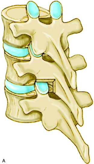
For the placement of the pedicle hook, a notch must be cut into the inferior facet so that the hook shoe can fit into the pedicle (Fig. 36-15). The notch should allow the hook to sit against the lamina, which engage the pedicle. The vertical cut is made with an osteotome, removing the inferior facet to expose the lower half of the superior facet surface.
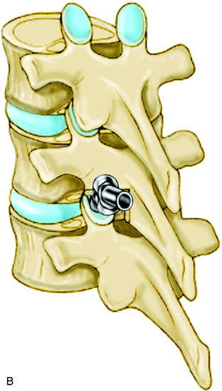
The pedicle finder is used to delineate clearly the orientation of the facet joint and the location of the pedicle. The tip of the hook initially should be directed cephalad and anteriorly so that it slides along the surface of the superior facet (Fig. 36-16).
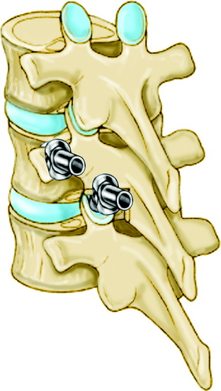
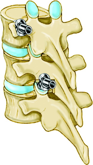
The hook-claw construct may be either single level or two levels (i.e., either the hooks on the same vertebrae or spanning two vertebrae [Figs. 36-17 and 36-18]). Claw constructs should bridge two levels, as opposed to bridging only a single level. This has been shown to be a stronger construct. Two sets of claw hooks are required for stable fixation (Figs. 36-19 and 36-20). The most commonly used claw configuration is the transverse process hook-two pedicle hooks. Three levels are included in one claw.
SUPPLEMENTAL HOOK FIXATION
When surgeons do short segment pedicle screw instrumentation from T12–L2, infralaminar and sublaminar hooks can be added (Fig. 36-21). If the supplemental hook is used, the stiffness increases in all modes of motion more than 200%, and pedicle screw bending moments decrease down to half.
POSTERIOR INSTRUMENTATION IN OSTEOPOROTIC SPINE
When the biomechanical test was performed with laminar hooks, pedicle screws, and Wisconsin wires, the mean tensile loads to failure for each of the implants tested were as follows: laminar hooks > screws > Wisconsin wires. The difference between the loads to failure for laminar hooks and the other implants was significant. Loads to failure for laminar hooks did not correlate with bone mineral density.13 Among the posterior implants, laminar hooks were most resistant to failure from posteriorly directed forces.
Case I
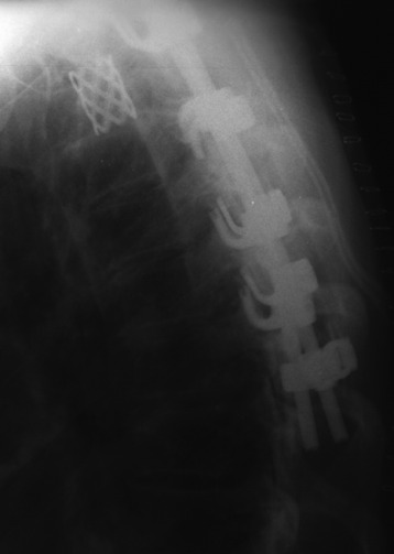
An 82-year-old male patient had a stabilization operation from T10 to L2 with posterolateral fusion (Fig. 36-22). However, postoperatively he suffered from gradually increasing back pain. He showed no neurological deficit. There were underlying diseases such as atrial fibrillation, coronary heart disease, and severe osteoporosis.
On follow-up x-ray 1 month later, the uppermost screw was seen to back out and cut out through the disc (Fig. 36-23), and T9 and T10 vertebral body collapse was seen.
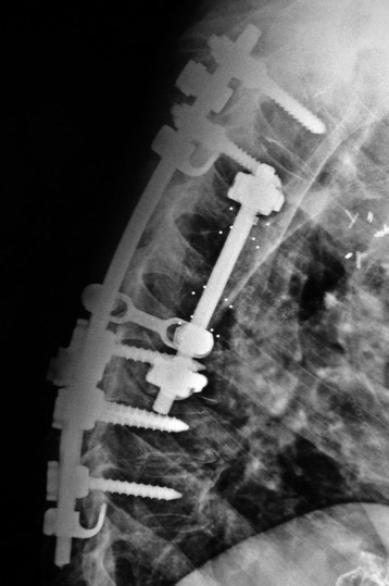
Revision operation was performed with the hook and screw system (Fig. 36-24).
Case II
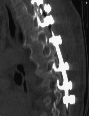
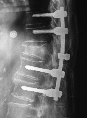
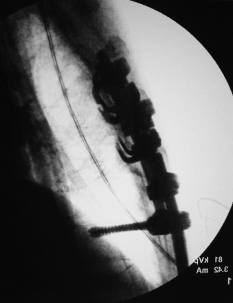
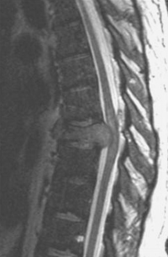
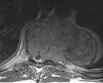
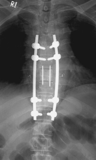
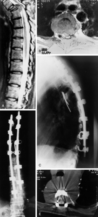
A 56-year-old male patient who was diagnosed as having multiple myeloma complained of severe back pain with paraparesis. The patient’s American Spinal Injury Association (ASIA) grade was C and he could not ambulate by himself. Magnetic resonance imaging (MRI) showed that a large vertebral body mass had developed at the T9 level and had grown to the left paravertebral space. The spinal cord was severely compressed (Figs. 36-25 and 36-26). The tumor was radiosensitive. However, the neurological state was critical, and the development of the pain was thought to be caused by spinal instability. Hence, the operative treatment was performed using a posterolateral transpedicular approach. The vertebral body mass was removed and the corpectomy site was replaced with bone cement and Steinmann pins (Figs. 36-27 and 36-28). Posterior stabilization was performed with the pedicle screw system at two levels above and two levels below.
Case III
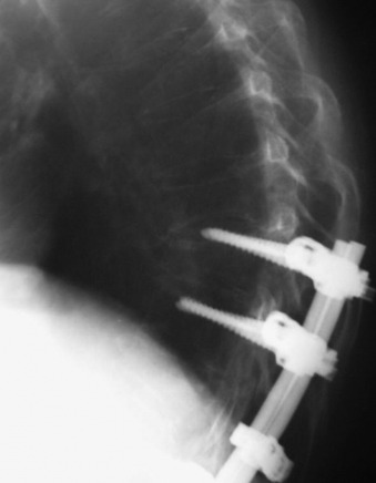
This patient is a 30-year-old woman who had a high-grade spindle cell sarcoma resected from the thoracolumbar paraspinal area in 1993, followed by external beam radiation therapy (RT) and brachytherapy. She was disease-free until April 1994, when she underwent a left upper lobectomy for a pulmonary metastasis, followed by right upper and middle lobectomies 1 year later for recurrent metastasis. She subsequently underwent bilateral chest wall resections for symptomatically recurrent metastasis. In February 1998, she was seen for 3 days of acute back pain that had improved from severe to moderate. She had no neurological symptoms. An MRI scan showed high-grade spinal cord compression at T4 with a pathological compression fracture and kyphosis (Fig. 36-29, A and B). Because of the multiple previous surgeries, the thoracic surgeons did not believe she would tolerate a thoracotomy. A transpedicular approach at T4 was performed (Fig. 36-29, C and D), and she was discharged with a neurologically normal state (ASIA grade E). She declined postoperative RT and chemotherapy. She developed recurrent back pain and was categorized as ASIA grade D and Eastern Cooperative Oncology Group (ECOG) grade 2 in September 1998. Myelography showed recurrent tumor with epidural compression at T4 (Fig. 36-29, E). She underwent decompression through a posterior approach with resection of the epidural and paraspinal tumor to the level of the anterior vertebral body replacement. Because of the previous thoracic procedures and the prospects for future RT, a trapezius flap was rotated over the hardware before skin closure. She returned to ASIA grade E and ECOG grade 4 status and received postoperative RT without experiencing wound complications.
[/level-membership-for-neurosurgery-category][not-level-membership-for-neurosurgery-category]
Chapter 36 Posterior Stabilization in the Thoracic Spine
POSSIBLE OPTIONS IN THORACIC INSTRUMENTATION
Several posterior stabilization techniques have been used in patients with spinal tumors.1,2 Harrington distraction rods have long been used after resection of lesions of the thoracic and lumbar spine. But the Harrington three-point fixation system is likely to fail because of excessive bending loads when the anterior and middle vertebral columns are eroded by tumor. Segmental spinal fixation with a wire and rod system, introduced by Luque, provided more rigid fixation than the Harrington system. The major concerns associated with this system were complications related to the epidural passage of multiple sublaminar wires and limitations on the ability to resist axial forces. The hook system offered rigid segmental fixation and improved the ability to achieve spinal alignment in three dimensions. However, hook segmental fixation requires the presence of intact laminae and facets, and multiple motion segments above and below the level of tumor involvement should be fitted with the construct. The pedicle screw system provides the most rigid and stable construct, covering three columns with short segment application.3,4 Systems with increased stiffness and stability allow early mobilization without external immobilization. The rod hook/rod pedicle screw system has a stiffer construct compared with Luque rods or with wiring to Harrington rods.5
THORACIC WIRING
Sublaminar wires are often used in conjunction with the rods to provide rigid segmental stability to the posterior spine.6 Wire placement at the end of the instrumentation construct resists implant pullout in the sagittal plane (Fig. 36-1). The risk of bone/implant failure is lessened with this technique because of the multitude of points of fixation contact (Fig. 36-2).
TECHNIQUES OF WIRING
The radius of curvature of the bent sublaminar wire should be at least equal to the width of the lamina. The wires should be passed anterior to the lamina in a caudal to cranial direction and a lateral to medial direction. The tip of the wire should remain in contact with the undersurface of the lamina as it is advanced cranially (Fig. 36-3). The wire should be rolled so that the tip emerges at the upper end of the lamina in the midline. The looped leading edge can then be grasped with a nerve hook or narrow needle holder. The wire is then pulled through with a firm posterior force on the leading and trailing edge of the wire. The wire ends are bent to conform to the posterior lamina. Once the wire is passed, it should be twisted over the respective posterior lamina to prevent inadvertent canal migration.
Harrington distraction rods with segmental wiring provide the best axial load stability. Luque segmental wiring, a semi-rigid fixation device, is best for rotational stability for burst fracture management (Fig. 36-4).7 The rod on each side of the midline is cut to the appropriate length and placed along the lamina. The wires are twisted around the rods. L-shaped rods are usually used. The L-shape aids in settling of the spine and prevents rod rotation. The L should be passed across the midline through an interspinous space and underneath the straight aspect of the opposing rod. This prevents the dorsal protrusion of the L-aspect of the rod. Wires are tightened down alternately, and double wires are recommended at the ends of the construct.
TRANSPEDICULAR SCREW FIXATION IN THORACIC SPINE
ANATOMY
There is no epidural space between the pedicle and dura.
The average distance between the pedicle and adjacent nerve root is known to be 1.9–4.1 mm superiorly and 1.5–3.2 mm inferiorly. There is a narrow safe zone (1–2 mm) between the pedicle and nerve root. Medial-lateral width of the pedicle is smaller than the superior-inferior diameter. The pedicle diameter decreases from the upper thoracic level to the middle thoracic level, then increases from the middle level to the lower level. The sagittal inclination decreases from T1 to T12.8 The medial inclination is greatest at the upper level, being straight at the middle and lower levels.
SURGICAL TECHNIQUES
Starting Point (Entry Point)
The entry point varies according to the level of thoracic spine:
