[level-membership-for-neurosurgery-category]
Chapter 35 Posterior Stabilization in the Cervical Spine and Cervicothoracic Junction
WIRING
Wiring on the posterior cervical element is effective in preventing flexion and less effective in preventing extension and axial rotation. All wiring methods are reported to restore a level of stability comparable to the intact spine when they are applied.1
INTERSPINOUS WIRING
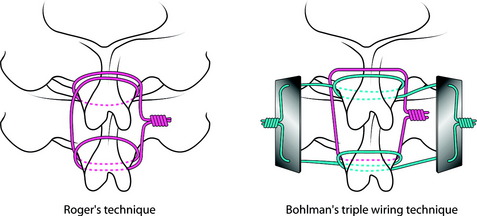
Fixation of the posterior cervical spine with interspinous wiring is well known as Roger’s or Bohlman’s technique. Most biomechanical studies show no significant difference between Roger’s and Bohlman’s triple wiring with bone graft.1,2 In Roger’s technique, multistrand cable is passed through and around the base of the spinous process (Fig. 35-1). In Bohlman’s triple wiring technique, two cables are looped around and grasp the spinous process and compress the bone graft, promoting the corticocancellous bone graft. Bohlman’s technique is usually preferred.
SUBLAMINAR WIRING
Sublaminar wiring has no biomechanical advantages over interspinous wiring. However, there are some risks of neurological injury in the application of the sublaminar wire, which is estimated up to 17%. Cables are generally safer than wires.2
Clinical Indications
Technique
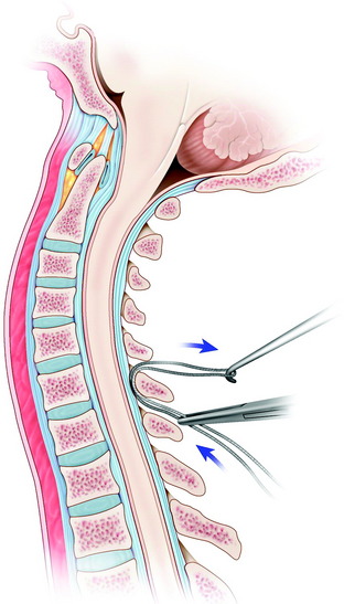
After the interspinous space is dissected, the ligamentum flavum is exposed at the levels of wire placement. The double-bent wire is introduced at the midline of the inferior edge of the lamina. The tip of the wire should remain in contact with the undersurface of the lamina as it is advanced cranially. The looped leading tip of the wire is grasped at the cranial side and bent over the posterior surface of the lamina (Fig. 35-3).
LATERAL MASS SCREW FIXATION
Lateral mass screw fixation provides greater stability in lateral bending compared with the wiring methods.3 The entry point is at the midpoint of the lateral mass, aiming approximately 30 degrees cephalad and 30 degrees lateral (Figs. 35-4 and 35-5). The lateral angle will be less of an issue if shorter screws are used. According to other authors, the screwing direction can be variable.
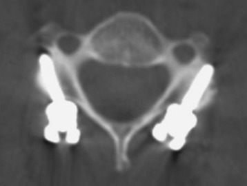
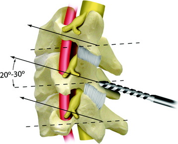
Roy-Camille4 used a screwing angle of 0 degrees cephalad and 10 degrees lateral. Magerl5 used a larger 40- to 60-degree cephalad angle and 25-degree lateral angle. This angle is known to provide stiffer pullout strength than Roy-Camille’s angle.6 An7 used the less cephalad angle of 15 degrees cephalad and 30 degrees lateral, which is the safest angle with respect to neurovascular injury. The optimal length of the screw is 14 mm for the average male and 12 mm for the average female. At these screw lengths, injury to the vertebral artery is unlikely.
For the stiff construct, the bicortical purchase is desirable. However, the pullout strength is known to be similar between the bicortical and unicortical purchases.8 With respect to safety, the unicortical purchase is favored. For connection of the screws, the rod or plate is selected. The rod provides an easier method to place screws in multiple lateral masses than does the plate. The cross-link with the rods increases flexural stiffness but provides no difference in lateral bending or torsion.9
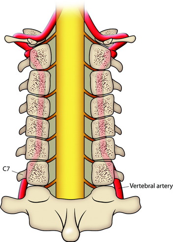
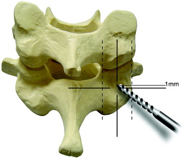
If a lateral mass screw is used at the C7 level, consideration of the VA should be made. If the screw is too long or is directed less than 14 degrees laterally from the midpoint of the lateral mass of C7, the VA may be in at risk of injury (Fig. 35-6). Aiming too caudal with the lateral mass screws may lead to spinal nerve injury. Furthermore, the C6 and C7 lateral masses are thinnest in the cervical spine because they are in transition to becoming transverse processes. The safest trajectory at C6 and C7 seems to be 30 degrees lateral and 30 degrees cephalad when using a starting point 1 mm medial to the center of the lateral mass (Fig. 35-7).
PEDICLE SCREWS
The entry point of C7 transpedicular screwing is located at the junction of two lines: the vertical line passing by the middle of the C6–7 facet joint and the horizontal line passing just (1 mm) under the middle of the C7 transverse process (Fig. 35-8). Direction of screwing is 30–35 degrees medially and 5 degrees downward with reference to the C7 lower endplate (Fig. 35-9).
COMBINATION WITH ANTERIOR STABILIZATION
Posterior plating with an interbody graft is biomechanically superior to anterior plating with locked fixation screws for stabilizing the corpectomy model. It also was found that combined anterior and posterior fixation may not improve the stability significantly as compared with lateral mass screws and interbody graft.10 When posterior stabilization is used with the interbody graft, the anterior plating does not provide additional stability.
POSTERIOR STABILIZATION OF CERVICOTHORACIC JUNCTION
CERVICOTHORACIC JUNCTION BIOMECHANICS
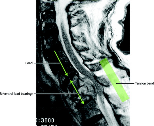
Biomechanically the CTJ is exposed to large forces, particularly in flexion and distraction (Fig. 35-10). At this region, disruption to any two columns should be regarded as unstable and should be treated accordingly. Posterior fixation devices have proved to restore the stability of the diseased spine to that of the intact spine for a two-column injury. Additional anterior stabilization is warranted when three-column injury occurs. In the stabilization of the CTJ, a posterior hook and rod system provides a construct six times stiffer than the anterior plating system. The screw and rod system is stiffer than the hook and rod system. Considering the strength of the construct and the technical aspect, lateral mass screws are chosen for levels C3 to C6 and pedicle screws are favored for C1, C2, C7, and thoracic spines. In most cases, the facet joints are removed because of tumor infiltration, so the fixation point is lost and should be moved to adjacent levels, which results in long segment fixation.
CASE ILLUSTRATION
Cervical Lateral Mass Screw-Thoracic Hook Combination
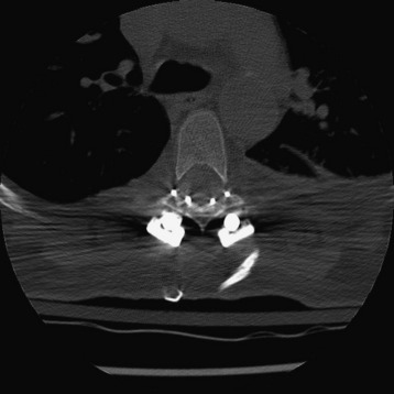
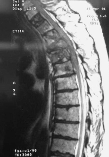
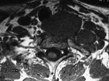
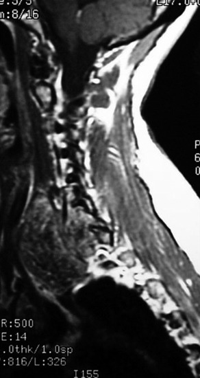
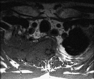
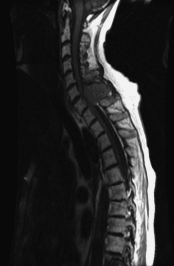
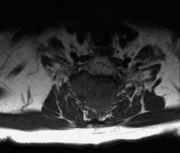
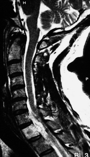
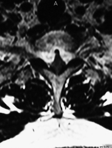
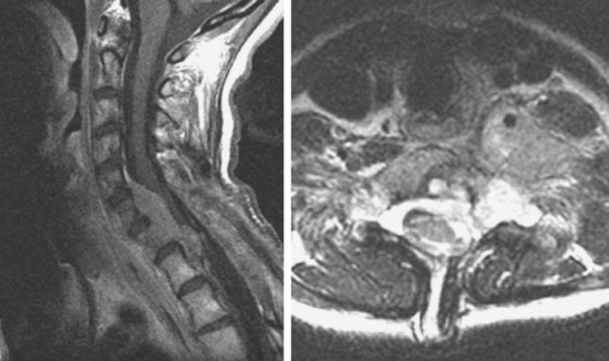
Preoperative magnetic resonance imaging (MRI) shows a T2 mass destructing the vertebral body, left pedicle, and posterior elements (Fig. 35-11). The spinal cord was compressed and displaced to the right side (Fig. 35-12).
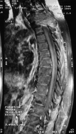
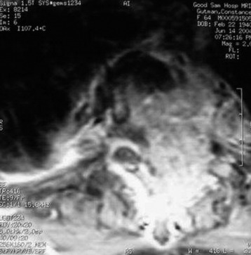
Fig. 35-12 Preoperative MRI, axial view. The spinal cord is compressed and displaced to the right side.
An operation was performed using the posterior parascapular extracavitary approach.
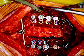
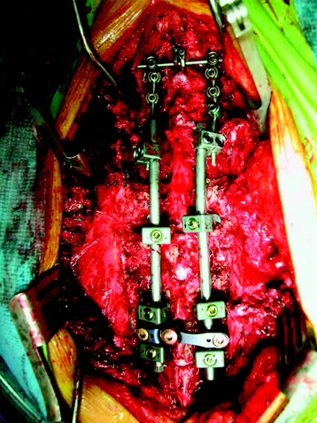
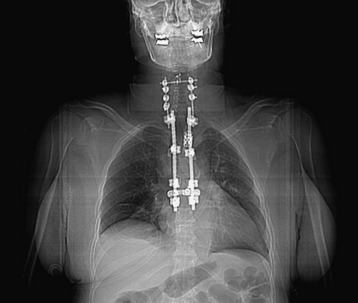
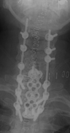
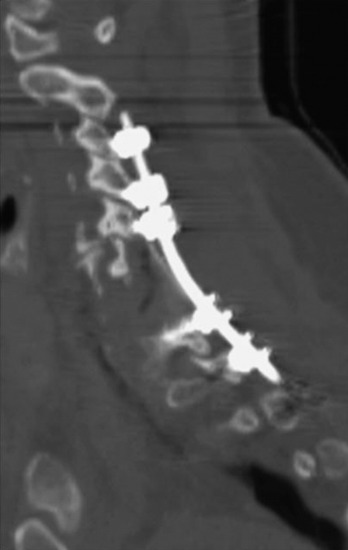
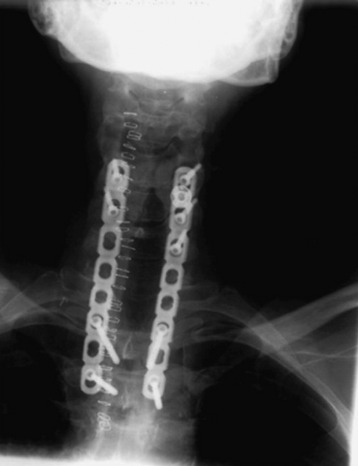
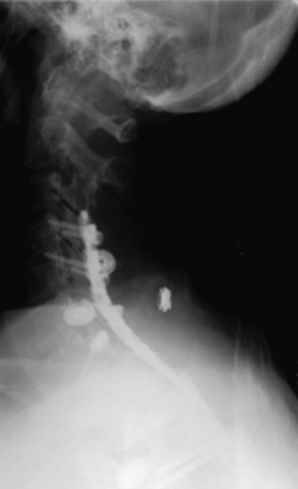
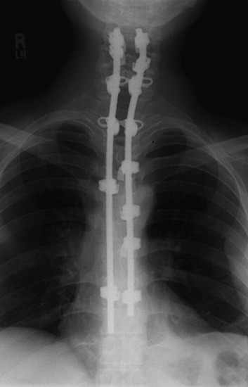
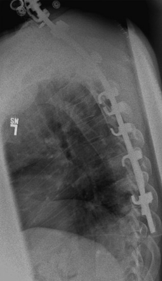
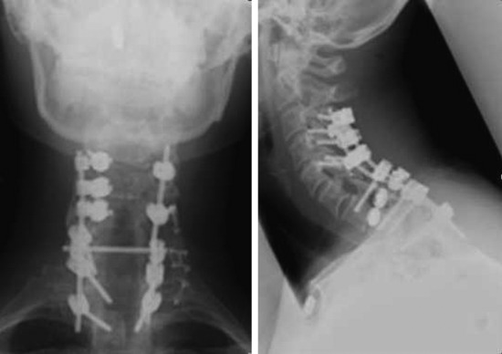
After the posterior elements were removed, the spinal cord was identified. The left T2 nerve root was identified, dissected, and cut. The cut end of the T2 nerve root was retracted to the right side to facilitate the transpedicular corpectomy. After the corpectomy, the mesh graft was inserted. Posterior stabilization was performed as follows. Polyaxial lateral mass screw fixation (C3, C4, C5, and C6) and thoracic hook application were accomplished (T3 transverse process hook, T5 laminar hook, and T6 pedicular hook) (Fig. 35-13). C7 and T1 were skipped. Dual-diameter rods were interlinked with connectors (Fig. 35-14). Two cross-links were used for quadrilateral stability (Fig. 35-15). To prevent cervical screw pullout, the reinforcement was performed with a Songer cable secured to the upper cross-link. Another potential option is to extend the cervical construct rostrally to incorporate a C2 pedicle screw fixation.
Cervical Wiring and Thoracic Hook Combination
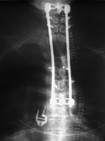
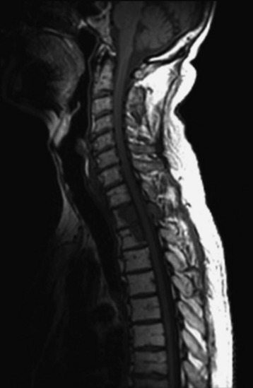
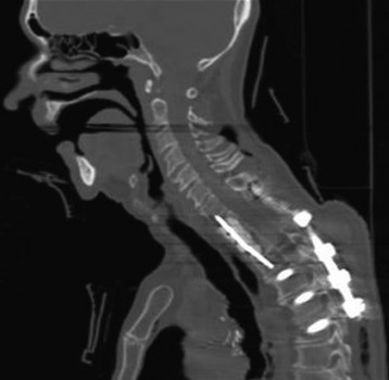
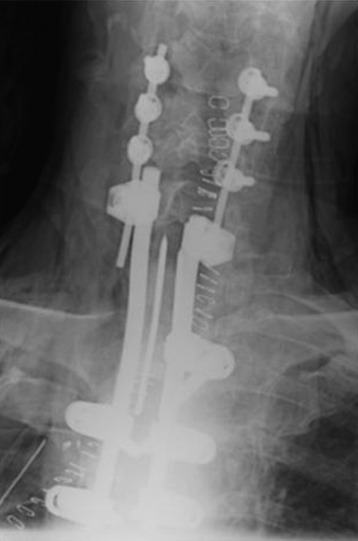
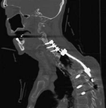
A patient with metastatic lung cancer involving C7–T4 presented with myelopathy and had already received a full course of radiation therapy (Fig. 35-16). Decompressive laminectomy was performed from C7 to T4. The patient did not undergo anterior decompression. Stabilization was achieved with cervical sublaminar wires secured to the cross-link and with the use of thoracic hooks below the decompression site (Figs. 35-17, 35-18 and 35-19). Of three thoracic hooks, the upper one was a transverse hook and the lower two were pedicle/facet hooks. The transitional rod can accommodate small cervical implants and large thoracic implants.
Cervical Lateral Mass Screw and Thoracic Pedicle Screw Combination
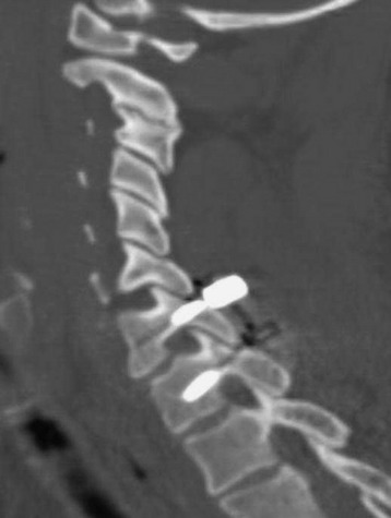
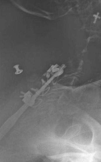
This C7, T1 chordoma was protruding anterolaterally. The tumor mass destroyed the anterior cortical margin and displaced anterior viscerovascular structures (Figs. 35-20 and 35-21).
The posterior cortical margin was intact, and the spinal cord was not compressed.
The operation was performed first with an anterior approach; a C7 and T1 corpectomy was performed. The anterior stabilization was achieved with an autologous iliac crest graft, and plating was applied from C6 to T2. Supplementary posterior fixation was performed from C3 to T3 with a cervical lateral mass screw and thoracic pedicle screws. The screws were connected with a transitional rod (Figs. 35-22 and 35-23).
Screw-Rod Systems with Dual Diameter Rods
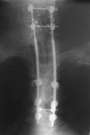
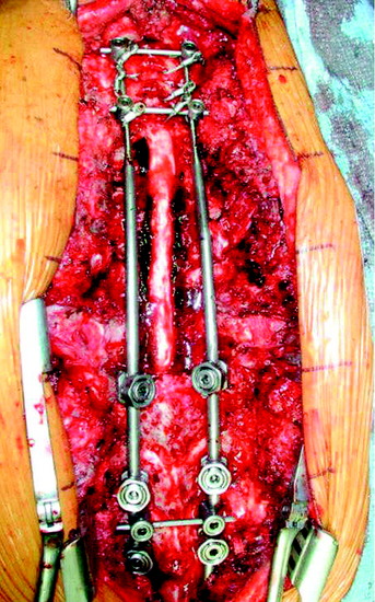
This patient was diagnosed with non-small cell lung cancer. The tumors destroyed the T2 and T3 vertebral bodies and extended to the right paraspinal area (Figs. 35-24 and 35-25). The operation was performed using the posterior approach with chest wall excision. A posterolateral thoracotomy and a T2, T3 vertebrectomy were performed. The lateral mass screws were purchased to the C4, C5, and C6 levels, and the pedicle screws were fixed to the T4, T5, and T6 levels (Figs. 35-26 and 35-27). The screws were interconnected with interlocking connectors (Fig. 35-28).
This patient has the C6, C7 metastasis of thyroid cancer (follicular type). The tumors involved the posterior element only (lamina and bilateral facets) (Figs. 35-29 and 35-30). Posterior decompression and posterior stabilization were performed. Posterior decompression was composed of laminectomy and bilateral facetectomy. The stabilization was made from C4 to T2 with lateral mass screws and plate (Figs. 35-31 and 35-32).
This patient with non-small cell lung cancer received radiation therapy for T1 metastasis. After a short period of pain relief, he showed progressive myelopathy. MRI showed that an epidural mass had developed at the C7 and T1 levels (Figs. 35-33 and 35-34). The operation was performed with C6 to T1 posterior decompression including C7, T1 facetectomy. For the stabilization, sublaminar hooks were applied from C4 to T7 (Figs. 35-35 and 35-36).
Screw Rod System (Lateral Mass and Pedicle Screw Construct)
A 40-year-old male patient presented with left forearm and hand paresthesia. An MRI showed compression of the spinal cord by an epidural mass located from C5 to T1 and ventral to the spinal cord (Fig. 35-37). The operation was performed using the posterior approach.
To directly connect the screws, lateral offset connectors were used at the lateral mass screw heads (Fig. 35-38). The entry points of the lateral mass screw are located at the medial side compared with those of the pedicle screw.
[/level-membership-for-neurosurgery-category][not-level-membership-for-neurosurgery-category]
Chapter 35 Posterior Stabilization in the Cervical Spine and Cervicothoracic Junction
WIRING
Wiring on the posterior cervical element is effective in preventing flexion and less effective in preventing extension and axial rotation. All wiring methods are reported to restore a level of stability comparable to the intact spine when they are applied.1
INTERSPINOUS WIRING
Fixation of the posterior cervical spine with interspinous wiring is well known as Roger’s or Bohlman’s technique. Most biomechanical studies show no significant difference between Roger’s and Bohlman’s triple wiring with bone graft.1,2 In Roger’s technique, multistrand cable is passed through and around the base of the spinous process (Fig. 35-1). In Bohlman’s triple wiring technique, two cables are looped around and grasp the spinous process and compress the bone graft, promoting the corticocancellous bone graft. Bohlman’s technique is usually preferred.
SUBLAMINAR WIRING
Sublaminar wiring has no biomechanical advantages over interspinous wiring. However, there are some risks of neurological injury in the application of the sublaminar wire, which is estimated up to 17%. Cables are generally safer than wires.2
Clinical Indications
Technique
After the interspinous space is dissected, the ligamentum flavum is exposed at the levels of wire placement. The double-bent wire is introduced at the midline of the inferior edge of the lamina. The tip of the wire should remain in contact with the undersurface of the lamina as it is advanced cranially. The looped leading tip of the wire is grasped at the cranial side and bent over the posterior surface of the lamina (Fig. 35-3).
LATERAL MASS SCREW FIXATION
Lateral mass screw fixation provides greater stability in lateral bending compared with the wiring methods.3 The entry point is at the midpoint of the lateral mass, aiming approximately 30 degrees cephalad and 30 degrees lateral (Figs. 35-4 and 35-5). The lateral angle will be less of an issue if shorter screws are used. According to other authors, the screwing direction can be variable.
Roy-Camille4 used a screwing angle of 0 degrees cephalad and 10 degrees lateral. Magerl5 used a larger 40- to 60-degree cephalad angle and 25-degree lateral angle. This angle is known to provide stiffer pullout strength than Roy-Camille’s angle.6 An7 used the less cephalad angle of 15 degrees cephalad and 30 degrees lateral, which is the safest angle with respect to neurovascular injury. The optimal length of the screw is 14 mm for the average male and 12 mm for the average female. At these screw lengths, injury to the vertebral artery is unlikely.
For the stiff construct, the bicortical purchase is desirable. However, the pullout strength is known to be similar between the bicortical and unicortical purchases.8 With respect to safety, the unicortical purchase is favored. For connection of the screws, the rod or plate is selected. The rod provides an easier method to place screws in multiple lateral masses than does the plate. The cross-link with the rods increases flexural stiffness but provides no difference in lateral bending or torsion.9
If a lateral mass screw is used at the C7 level, consideration of the VA should be made. If the screw is too long or is directed less than 14 degrees laterally from the midpoint of the lateral mass of C7, the VA may be in at risk of injury (Fig. 35-6). Aiming too caudal with the lateral mass screws may lead to spinal nerve injury. Furthermore, the C6 and C7 lateral masses are thinnest in the cervical spine because they are in transition to becoming transverse processes. The safest trajectory at C6 and C7 seems to be 30 degrees lateral and 30 degrees cephalad when using a starting point 1 mm medial to the center of the lateral mass (Fig. 35-7).
PEDICLE SCREWS
The entry point of C7 transpedicular screwing is located at the junction of two lines: the vertical line passing by the middle of the C6–7 facet joint and the horizontal line passing just (1 mm) under the middle of the C7 transverse process (Fig. 35-8). Direction of screwing is 30–35 degrees medially and 5 degrees downward with reference to the C7 lower endplate (Fig. 35-9).
[/not-level-membership-for-neurosurgery-category]
