Chapter 31 Posterior Minimally Invasive Procedures to Spine Tumors
VERTEBROPLASTY TECHNIQUE
TRANSPEDICULAR APPROACH
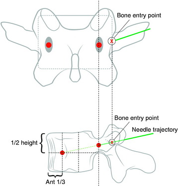
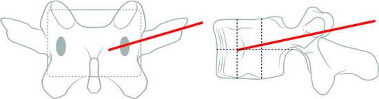
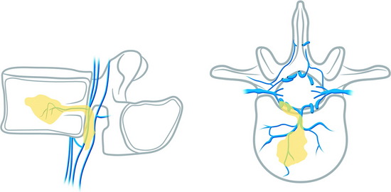
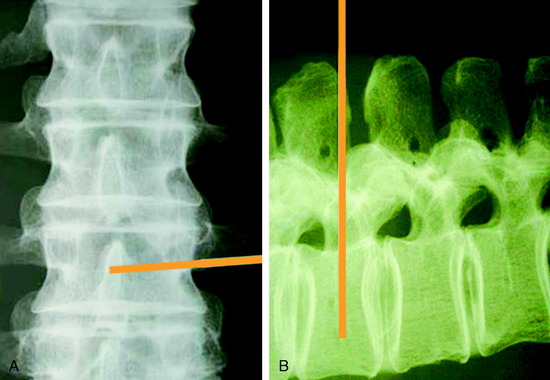
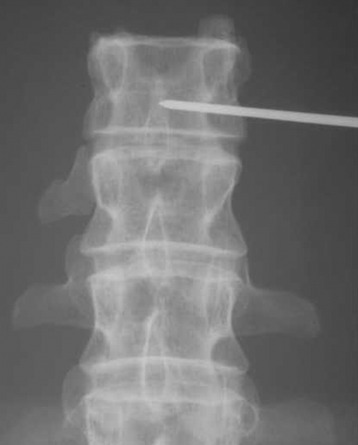
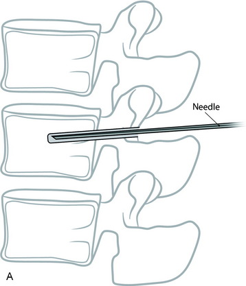
Under fluoroscopic assessment, a 10- to 15-gauge 10- to 15-cm length needle, preferentially with a beveled cutting tip, is inserted along the selected pedicle (Fig. 31-1).1 Within the pedicle, the bevel of the needle is oriented medially (the tip of the needle pointing laterally) to avoid the spinal canal. Once within the vertebral body, the bevel is rotated to face laterally (the tip of the needle pointing medially), directing the needle medially, toward the midline. The most desirable position of the needle tip is the anterior third of the vertebral body near the anteroposterior midline (Fig. 31-2). When dealing with a vertebra plana, a more lateral position of the needle is desired. If the underlying pathological condition remains uncertain before the cement injection, a bone biopsy specimen can be obtained using a 15- to 18-gauge biopsy needle placed through the vertebroplasty (VP) needle. Then vertebral venography is performed to evaluate the flow dynamics. When a high-flow, hypervascular pattern is observed, the reposition of the needle tip may be required to perform an embolization of the venous channels, either with alcohol, N-butyl-2-cyanoacrylate (Histoacryl), Gelfoam, plugs, or Avitene powder before cement injection. After the powder and a liquid component are mixed and the desired consistency is reached, the polymethyl methacrylate (PMMA) is injected through the needle. The injection is continued until resistance is met, or the cement reaches the posterior wall of the vertebral body, or a desired result is achieved. The injection should be stopped if epidural, foraminal, or venous leakage is detected.
VERTEBROPLASTY IN CERVICAL LESIONS
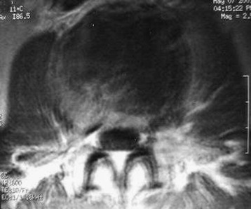
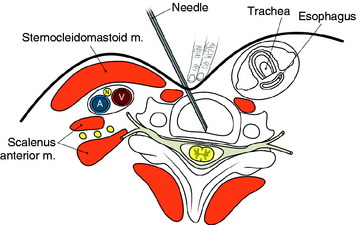
The entry points are along the anterior margin of the sternocleidomastoid (SCM) muscle. With lateral fluoroscopy, the appropriate level and entry height should be determined. After the entry point is marked, a small skin incision is made. The surgeon pushes the medial structures (trachea and esophagus) to the opposite side with index and middle fingers, then applies a firm pressure in the space between the SCM muscle and the trachea, pointing toward the vertebral surface. The needle is then inserted through the space between the trachea and carotid sheath (Fig. 31-3).
CASE ILLUSTRATION
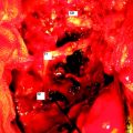
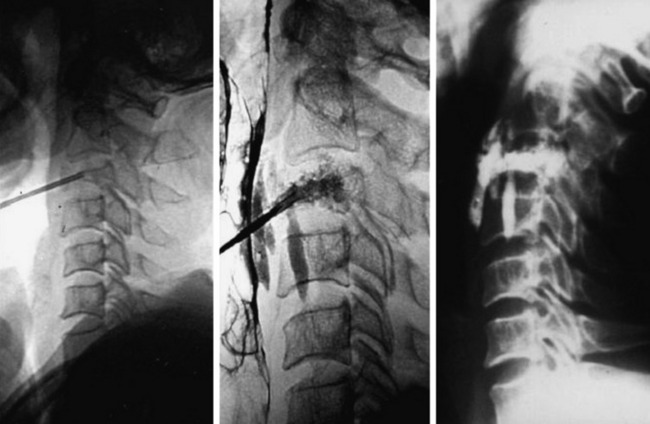
A 45-year-old woman with breast cancer was treated with VP at C3 metastasis (Fig. 31-4). The approach was performed from the left side, with finger compression of the visceral tissue. During VP, esophagography should be performed to check the esophageal injury. Bone cement of 2cc was injected to the compressed C3 body. A small amount of bone cement was seen to leak into the paraspinal space. Preoperative neck pain was much improved after VP.
BIOMECHANICS: VOLUME OF BONE CEMENT
The effective volume of bone cement is estimated to be from 3 to 10cc; however, a study on the effects of bone cement volume and distribution on vertebral stiffness after VP showed that 14% filling or 3.5cc was necessary to restore stiffness of the damaged vertebral body to the pre-damaged value at the lumbar level.2 This result suggests that large fill volume may not be the most biomechanically optimal configuration, and an improvement might be achieved by use of a lower cement volume with symmetrical placement. Also, with the unipedicular approach, the stiffness comparable to the intact body can be achieved in cases of symmetrical distribution of bone cement.
COMPLICATIONS
Pulmonary Embolism
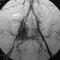
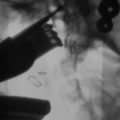
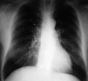
Pulmonary embolism may occur during the VP. Bone cement leaked from the vertebral body via the venous channel can enter the systemic circulation. It may be filtered in the pulmonary circulation system (Fig. 31-5). Even though pulmonary embolism does occur, most patients may be asymptomatic. If symptomatic, patients complain of tachypnea and respiratory difficulty. Tachycardia is monitored. The incidence of pulmonary embolism is 3–4%.3 Most patients can be treated with anticoagulant therapy and respond favorably.4
Neurological Complication (Epidural Leakage)
Epidural leakage may occur at a high incidence, up to 50–70% in osteolytic metastasis or myeloma. Most patients with epidural leakage are asymptomatic; however, few patients may undergo surgery because of radiculopathy. Epidural leakage can occur through the fracture line, cortical destruction, the needle track, or the epidural and paravertebral venous plexus (Fig. 31-6).
CASE ILLUSTRATION: EPIDURAL LEAKAGE
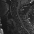
A 35-year-old female patient received VP for the treatment of L3 hemangioma. The bone cement leaked through the venous plexus into the epidural space and damaged the right L3 nerve root (Figs. 31-7 and 31-8). The patient suffered from right lateral thigh paresthesia for 6 months. After prolonged treatment with analgesics, the symptom was much improved.
SPECIAL PROBLEMS OF VERTEBROPLASTY IN CANCER PATIENTS
Venogram
The performance of a venogram in a tumor patient is controversial. Unlike with osteoporosis, venogram performed on tumors may result in substantial leakage of contrast into the canal and paravertebral spaces because of significant cortical destruction and bony erosion (Fig. 31-9).
Injection into the Tumor Mass
The injection of the cement into dense tumor mass tissue may be more difficult than in an osteoporotic spine, and the PMMA pattern may appear spotty and discontinuous.5 To provide maximum structural support, both the osteolytic portion of the vertebral body and the seemingly normal bone should be injected. Vascular tumors, such as renal cell cancer metastasis, may show frank arterial flow through the cannula once the stylet is removed. Hence, the trajectory track should be packed with PMMA to prevent excessive bleeding.
PARASPINAL TECHNIQUE: LUMBAR SPINE
Entry Point
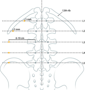
At the upper lumbar spine (L1 and L2), the entry point is just medial to the 12th rib. The midline and a line bisecting the transverse process and pedicle are identified (Fig. 31-10). The entry point is on the bisecting line and is 5mm medial to the 12th rib. The 12th rib is confirmed with fluoroscopy or palpitation of the rib. At lower lumbar spine (L3–5), a line bisecting the transverse process and pedicle is drawn. The entry point is located on the line, approximately 6–10cm away from the pedicle.
Trajectory Angle
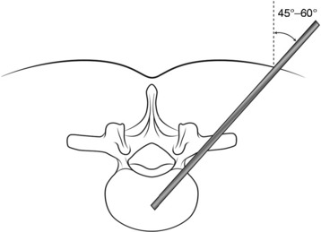
Typical trajectory angles are 45 to 60 degrees as measured from the vertical axis line of the patient (L1: 45–50 degrees, L2: 45–50 degrees, L3: 45–50 degrees, L4: 50–55 degrees, L5: 55–60 degrees) (Fig. 31-11).
Initial Trajectory
From the entry point, the needle is inserted with at the appropriate angle according to the vertebral body level (Fig. 31-12). After the soft tissue passage, the needle is advanced until it touches the lateral surface of the vertebral body. On fluoroscopic monitoring the needle tip is seen to locate just lateral and posterior to the vertebral body.
Approach to L5 Vertebral Lesion
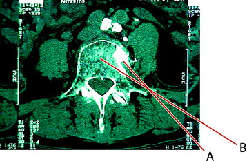
In cases of an L5 lesion, the approach angle should be more lateral than in the other levels (Fig. 31-13). The initial treatment was performed with suboptimal trajectory (line A). With this trajectory, the injected bone cemented leaked to paravertebral space. The next approach was done with a more lateral angle on a different entry point (line B).
PARASPINAL TECHNIQUE: THORACIC SPINE
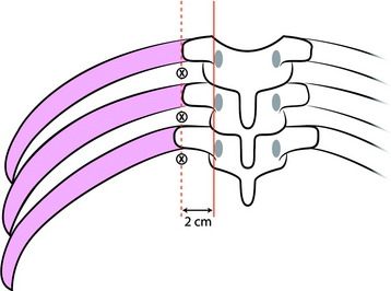
Entry Point
The lateral edge of the pedicle is identified, and the line is drawn (Fig. 31-14). Another line is drawn 2cm off the lateral edge line. The ribs and intervening soft tissue are identified using fluoroscopy or palpation. A punch incision is created at the soft spot and on the lateral line between the ribs.
Trajectory Angle
The angle of the needle entering the patient should be 55–60 degrees from the vertical axis (initial oblique approach). Using anteroposterior fluoroscopy, the needle is inserted at an oblique angle to target (dock) the lamina (Fig. 31-15).
Advancement
The needle is moved down the lamina to dock onto the vertebral ridge. The needle will drop off the lamina approximately 1cm onto the vertebral ridge (Fig. 31-16). Lateral fluoroscope is required for secure placement. When the needle reaches the vertebral ridge, the trajectory is adjusted toward 5 degrees lateral and advanced to the midpoint of the vertebral body.
VERTEBROPLASTY IN NEOPLASTIC SPINE DISEASE
INDICATIONS AND CONTRAINDICATIONS
In general, patients suffering from significant, focal, mechanical pain unresponsive to analgesia caused by osteolytic metastases or myeloma are candidates for VP.6
POLYMETHYLMETHACRYLATE-AUGMENTED SCREW FIXATION FOR STABILIZATION
Screw fixation augmented with bone cement has been used in patients with osteoporosis requiring spinal fusion.7 This technique can be used in patients treated for multilevel metastatic spinal tumors.
SURGICAL TECHNIQUE
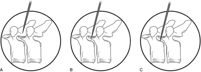
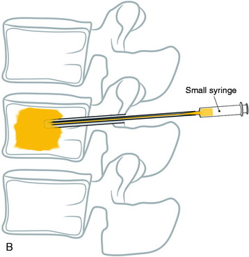
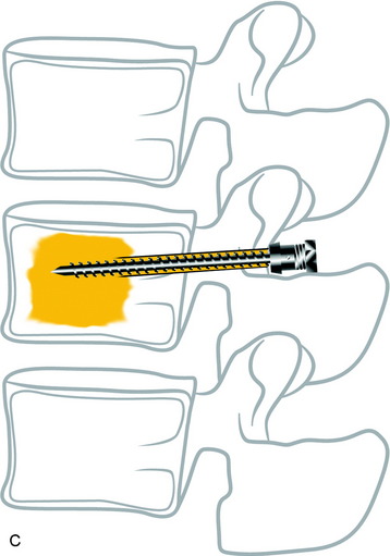
With the posterior approach, a hole is made for a pedicle screw in the weak vertebra, and a 10-gauge needle is inserted (Fig. 31-17, A). The PMMA is mixed with barium sulfate powder to increase radiopacity.8 After reaching adequate viscosity, the PMMA is loaded into several 1-mL syringes and injected through the needle, under fluoroscopic guidance (Fig. 31-17, B). If excessive force is required for the injection, a stylet is introduced into the needle, which makes it easier to inject the PMMA into the vertebral body. The injection is stopped as soon as the PMMA reaches the posterior wall of the vertebral body or is fluoroscopically observed to drain into the venous channel. The hollow tract in the pedicle is filled with the PMMA. The pedicle screw is inserted into the hole before the PMMA hardens (Fig. 31-17, C). No more than 3mL is injected at the unilateral side to prevent crossing over into the contralateral side. VP with PMMA or calcium phosphate increases pullout strength.9
CASE ILLUSTRATION
The use of PMMA is known to increase the pullout strength of the screw as a result of the anchoring effect of the bone cement, which penetrates the intratrabecular space. Maximal filling of the trabecula with PMMA can increase the pullout strength of the pedicle screws to twofold over that of non-augmented, similar bone quality vertebra. Fig. 31-18 shows an L1 metastasis of lung cancer. Cord compression was not seen. The patient, a 69-year-old man, complained of back pain without leg pain. Surgery was performed with posterior decompression only. The L1 lesion was not removed and bone cement was injected instead. The T12 and L2 vertebral bodies were osteoporotic. Bone cement was injected into the T12 and L2 first, and screws were inserted.
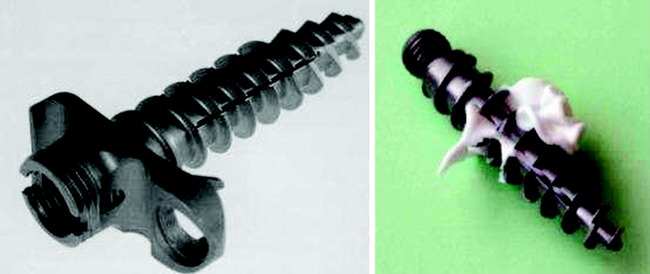
CEMENTABLE CANNULATED RESCUE SCREW
The bone cement can be injected into the cannula in the screw (Fig. 31-19). In biomechanical test, the cementable cannulated screw is known to have two times stronger holding power than the standard screw.10 In the vertebrectomy model, the strongest fixation is accomplished with combined reconstruction. However, when the cemented polyaxial screw is used in cases of the vertebrectomy model, it can provide similar stability comparable with anterior stabilization without dorsal defects, even in the presence of dorsal structural damage.11
VERTEBROPLASTY IN MULTIPLE MYELOMA
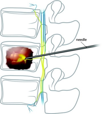
Multiple myeloma invades the bone marrow in the whole spine vertebral body. When the needle is inserted into the vertebral body, surgeons have difficulty in fixing the needle because the bone density is very low. When bone cement is injected, it spreads easily to the contralateral side of the vertebral body and even flows down to the pedicle in the approach side (Fig. 31-20).
CASE ILLUSTRATION
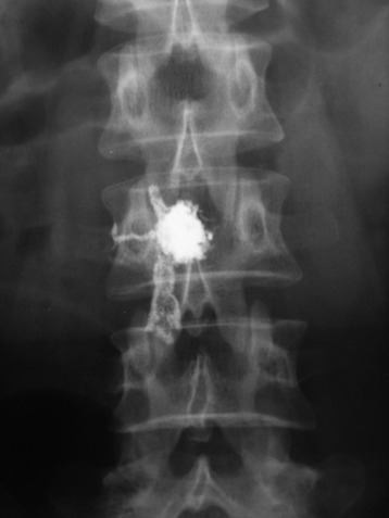
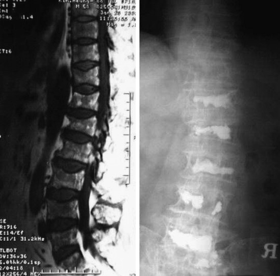
A 45-year-old multiple myeloma patient shows diffuse weakening of the vertebrae with myelomatous infiltration, which is a similar finding to osteoporosis (Fig. 31-21). Post-VP film shows that bone cement spreads well into the interior of the vertebral body. With the unilateral approach, bilateral filling can be easily achieved.
VERTEBROPLASTY IN VERTEBRAL BODY HEMANGIOMA
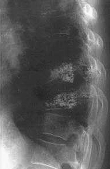
The symptom manifestation in vertebral body hemangioma (VH) can be caused by tumor-infiltrated vertebral body expansion, epidural invasion of the tumor, compression fracture, and epidural tumor bleeding.12 The VP operation in VH consolidates the vertebral body to prevent the body collapse (Fig. 31-22). Venous channel obstruction by bone cement reduces the risk of hemorrhage, which is the same effect as embolization. However, during VP, epidural leak of bone cement is more probable than in osteoporotic compression fracture,13,14 and bone bleeding into the epidural space can develop during the procedure.
CASE ILLUSTRATION
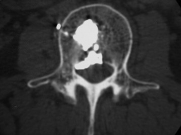
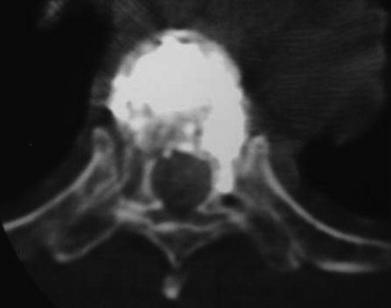
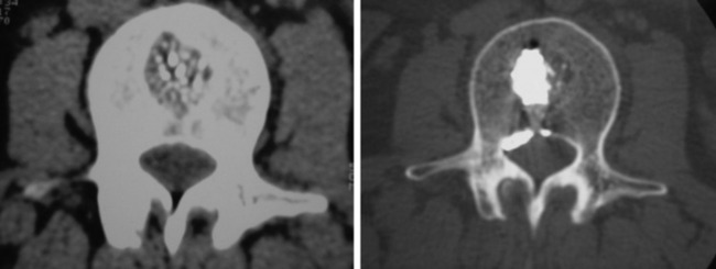
A 33-year-old female patient with L2 hemangioma on preoperative CT had the typical trabecular pattern in the bone marrow of L2 (Fig. 31-23). Bone cement is collected in the tumor mass of the vertebral body. After VP, paraparesis developed. Postoperative CT showed a mass suggestive of epidural leak at the VP level. After conservative treatment neurological function was recovered.
VERTEBROPLASTY IN OSTEOLYTIC METASTASIS
A 56-year-old woman with cervical cancer was diagnosed with L3 metastasis. She complained of severe back pain. On MRI, the low signal intensity lesion (T1-weighted image) was seen on the L3 vertebral body. Bone cement was injected into the low signal lesion that was thought to be the tumor infiltration area (Fig. 31-24).
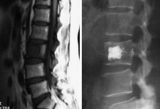
The spinal metastasis of cancer presents with osteolytic or osteoblastic lesions. In cases of an osteolytic metastasis, such as breast, lung, and cervical cancer, bone cement injection can relieve pain caused by vertebral body destruction.3 Bone cement fills the soft portion of the bone marrow, which takes an in-situ immobilization effect. The heat from the polymerizing cement can kill cancer cells and inactivates the nerve endings in the bone marrow. In cases of vascular tumors, such as renal cell metastases, embolic material should be inserted through the needle into the tumor mass before bone cement injection.
POSTEROLATERAL APPROACH FOR VENTRAL TUMORS IN CERVICAL SPINE
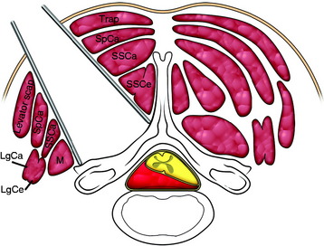
When the tumor-cord interface line projects posteriorly, a posterolateral approach can be adequate for tumor removal without cord damage.15 The skin incision is an extension of the line drawn along the tumor-cord interface. The superficial muscles are separated between the trapezius and lavatory scapulae. The intermediate muscle layers (semispinalis capitis, SSCa) are cut in the middle of them. Semispinalis cervicis muscle is retracted to the midline and the multifidus muscle is retracted to the lateral side (Fig. 31-25). The retractor blades are applied, exposing the base of the spinous process, laminae, and facets.
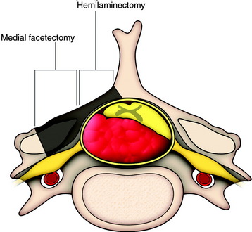
A bone window made by hemilaminectomy with additional removal of the base of the spinous process and medial portion of the facet joint should suffice for removal of tumors (Fig. 31-26).
TUMOR REMOVAL
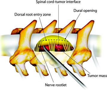
In cases of an extramedullary tumor, the dissection is begun at the cord-tumor interface first, toward the tumor mass (Fig. 31-27). Once the tumor is coagulated and shrinks away from the spinal cord with application of bipolar coagulation forceps, the lateral margin of the tumor is dissected from the surrounding tissues and removed.
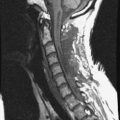
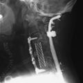
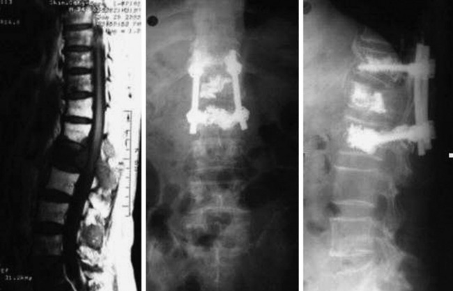
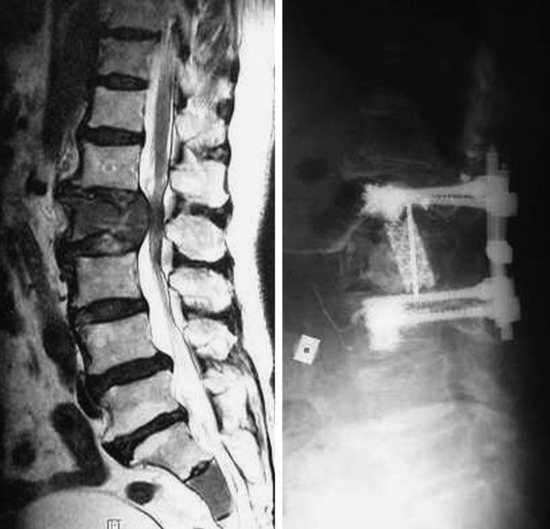
A 72-year-old man with back pain and pain radiating through both legs had been treated for lung cancer. MRI showed multiple spine osteolytic metastasis (L2, sacrum) (Fig. 31-28). Diffuse osteoporotic change was observed along the whole spine. A posterior approach was used for the neurological decompression. With the bilateral transpedicular approach, the L2 vertebral body lesion was resected. The vertebral body defect was reconstructed with mesh cage and bone cement. Posterior stabilization was achieved with PMMA-enforced pedicle screw fixation at the L1 and L3 levels.
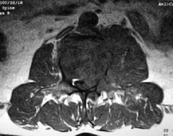
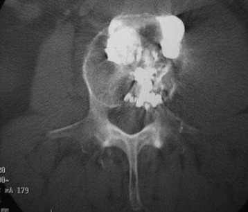
The mass formation was seen at the L3 vertebral body. The tumor mass destroyed the posterior cortex, and posterior bulging of the posterior longitudinal ligament was seen on the left side (Fig. 31-29). VP was performed through the left pedicle. The needle tip was located near the anterior margin of the vertebral body. With close monitoring with fluoroscopic guidance, bone cement was injected. When the bone cement reached the posterior margin of the vertebral body, the injection stopped. After the bone cement injection, CT was performed. Bone cement was filled into the osteolytic portion of the vertebral body (Fig. 31-30).
Even if posterior cortical destruction had existed, bone cement did not leak into the epidural space. After VP was finished, back and thigh pain were much improved. Chemotherapy followed the surgical treatment. Six months later, follow-up MRI showed that the posterior cortical bulging had disappeared and the dural sac was decompressed (Fig. 31-31).