Chapter 39 Posterior Lumbar and Lumbosacral Junction Stabilization
TRANSPEDICULAR SCREW FIXATION FOR LUMBAR SPINE
Pedicle screw fixation is indicated for the management of degenerative spinal disorders, as well as for fractures, infections, deformities, and spinal tumors in the lumbar spine. Especially in patients with malignant neoplasms, application of rigid posterior instrumentation is commonly needed to stabilize the spine after tumor resection. Pedicle fixation can be used at levels where a laminectomy or partial pedicle resection is required and provides rigid fixation over shorter segments. It offers the advantage of immediate stabilization, along with higher rates of fusion, easy contouring, and more available space for bone graft. A fusion rate from 88% to 95% in successful cases and a 6% pseudoarthrosis rate have been reported.1 In biomechanical studies,2 investigators have found that pedicle screw constructs provide greater rigidity than other forms of internal fixation, thus improving the potential for successful fusion. Segmental distraction, compressive, lordosis, rotating, and forward or backward forces can be applied, depending on the clinical situation. Finally, fixation can be limited to only adjacent spinal segments, allowing unaffected motion segments above and below to be spared. The pedicle screw-plating system was introduced first, which enables surgeons to perform only distraction and compression. The pedicle screw-rod system was adopted later, which allows axial, angular, and rotational adjustability, permitting instrumented segments of the spine to be held in distraction, compression, or derotation.
CLINICAL INDICATIONS OF PEDICLE SCREW FIXATION IN TUMOR SURGERY
TECHNIQUE OF PEDICLE SCREW FIXATION IN LUMBAR SPINE
Identification of the Entry Point
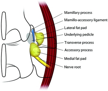
The midline incision is made in the lumbar spine. Subperiosteal dissection is made to split muscles from the spinous processes, laminae, and facets. On both sides, dissection is carried out to the level of the transverse processes in the region of the intended fusion. The surgeon should remove the musculature and the periosteum meticulously in the region of the segment to be fused. After the muscle is dissected, the fat tissue is seen from the base of the transverse process (lateral fat pad) and under the isthmus (medial fat pad). The superior articular process has two prominent bony ridges, the mamillary process and the accessory process. The mamillary process is located at the inferior aspect of the facet joint and is more laterally located at the lower spinal levels. A tendinous membrane (the mamilloaccessory ligament) connects the bony tips of the mamillary and accessory processes.3 The ligament is embedded medially and laterally in fat pads. The pedicle is located underneath the floor of the mamilloaccessory notch (Fig. 39-1). The ligament can be considered to be the lateral boundary of the pedicle.
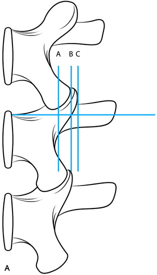
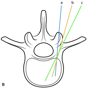
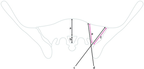
The entry point for the lumbar pedicle screw can be decided by other references. The entry point is usually determined as the intersection point between two lines. A bisecting line of the transverse process is commonly used as the horizontal line. The vertical line is variable according to the surgeons. Roy-Camille’s screw entrance point is situated on the vertical line given by the articular process 1 mm under the facet joint (Fig. 39-2, point a). In Margerl’s method, the vertical line touches the lateral border of the superior articular process (Fig. 39-2, point b). Some surgeons use the more lateral trajectory to avoid facet joint injury (Fig. 39-2, point c).
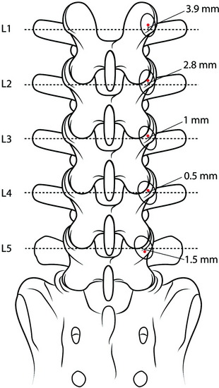
In most cases, the bisecting line of the transverse process coincides with the center of the pedicle. However, mild variations may be found depending on the level of the lumbar spine.4 The center of the cross-section of the pedicle is reported to be 3–4 mm higher than the bisecting line of the transverse process at L1, 2–3 mm higher at L2, and 0.5–1 mm higher at L3. At L4 and L5, the center of the pedicle is shown to be slightly lower than the bisecting line by 0.5–1.5 mm (Fig. 39-3).
Preparation and Screw Insertion
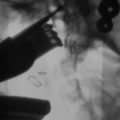
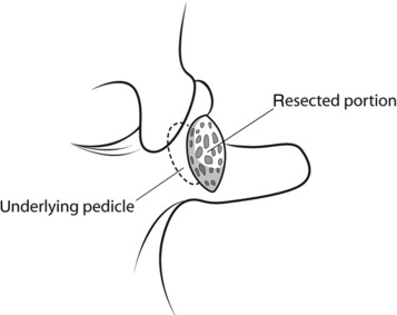
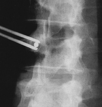
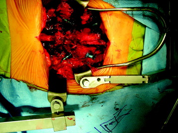
The medial and lateral fat pads are dissected bilaterally to expose the mamilloaccessory ligament. The pedicle is opened by grasping and rotating the bony ridge between the accessory process and the mamillary process with a rongeur (Fig. 39-4). After the pedicle is opened, marking wires (Steinmann pin) are inserted. The insertion angle of the Steinmann pin is 10–20 degrees convergent toward the sagittal plane (see Fig. 39-2). The point of entry is in the central axis of the pedicular tube, indicated by the intersection of the two lines. The vertical line touches the lateral border of the superior articular process. The horizontal line bisects the base of the transverse process. An x-ray is made to determine the exact position of the drill channels in the lateral and anteroposterior projections. In slightly oblique fluoroscopic images, the pedicle and Steinmann pin appear as an oval structure with a central dot (Fig. 39-5).
Anatomy of the Lumbar Spine Pedicles5
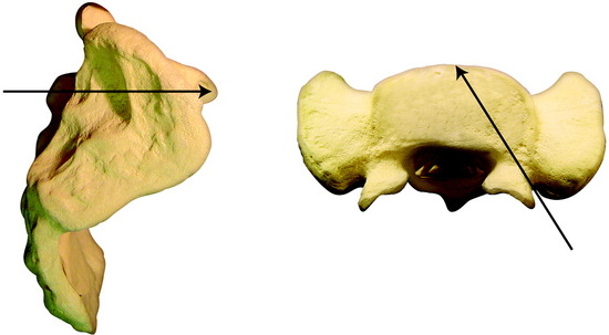
The transverse diameter of the pedicle is at its minimum at L1 (6–9 mm): it increases at lower levels and is at its maximum at the L5 level (12–18 mm). The diameter of the pedicle screw is determined to be 70–80% of the pedicle diameter. The axial length is at its minimum at L1 (47–53 mm) and at its maximum at the L3 level (49–56 mm), maintaining the stationary value to L5. The axial angle is at its minimum at L1 (8–15 degrees), increases at lower levels, and is at its maximum at the L5 level (25–35 degrees). The axial angles of the pedicles are reported to be significantly smaller in degenerative stenosis patients, as compared with a healthy control group, although no disease-related differences are recognized in the transverse diameter and axial length of the pedicles6. The axis of the pedicles in the coronal plane changes as the lumbar column descends; the axis of the pedicle of L5 is more horizontal and oblique than that of L1 (Fig. 39-6). These changes are correlated with changes in the course of the lumbar nerve because the lumbar rami run very close to the pedicle, as does the dorsal ganglion.6 Neural structures around the pedicle have three courses: ventral and dorsal nerve roots in the spinal canal, spinal ganglion in the foramen, and the spinal nerve in the extraforaminal space.
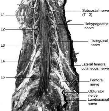
Relationship Between the Lumbar Pedicle and Adjacent Neural Structures
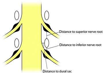
The average distance from the lumbar pedicle to adjacent nerve roots superiorly ranges from 4.1 mm at the L1 level to 5.5 mm at the L5 level.7 The distance at the L5 level is much wider than at the other lumbar levels. The region superior to the pedicle is a safe area where working cannulas can be used in percutaneous lumbar procedures for the management of lumbar disc herniations without risk of nerve injury.
Inside the canal, the spinal ganglion runs obliquely inferior to the pedicle. In the normal spine, the proximal half of the ganglion lies close to the inferomedial surface of the pedicle in the subpedicular zone, whereas the distal half runs steeply downward and away in the extraforaminal area (Fig. 39-7). Fracture of the pedicle inferiorly can impinge on the proximal ganglion, causing radicular symptoms. The symptoms may be increased by hyperflexion of the spine because stretching of the nerve root presses it against the inner surface of the upper pedicle of the corresponding intervertebral foramen. Average distances from the lumbar pedicle to the dural sac medially through the cranial to caudal lumbar levels range from 1.2 to 1.5 mm (see Fig. 39-6). The small space between the pedicle and the dural sac is the reason that pedicle fixation carries the risk of lacerating the dural sac.
The lateral distances from the pedicle to the exiting nerve root show mild variation from level to level. The shortest distance is found at L4 (2.3 ± 1.1 mm) and longest at L1 (4.8 ± 1.7 mm).6 If the surgeons violate the lateral wall of the pedicle, they may injure the upper level nerve root in the extraforaminal space.
Case I
When the tumor involves the anterior column and the posterior elements are intact, anterior decompression is performed with corpectomy. In this case, L3 corpectomy is performed, and graft is inserted. Anterior stabilization is accomplished with plate and screw (Figs. 39-8 and 39-9). Supplementary posterior stabilization is performed at the short segment (from L1 to L3).
Lesion Involving the L3 Vertebral Body and Posterior Element
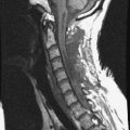
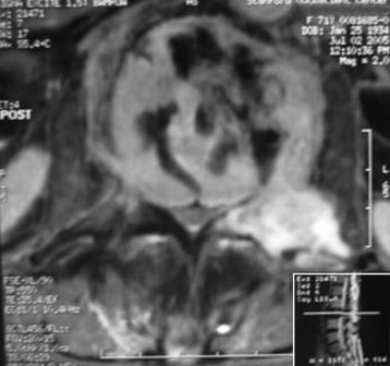
A 76-year-old woman presented with severe low back pain. She had mild trauma history. However, she did not show neurological abnormality. In the primary hospital, the work-up was done, and vertebroplasty was performed under the diagnosis of L3 osteoporotic compression fracture. When her symptoms did not improve, the magnetic resonance imaging (MRI) was re-checked. The T2-weighted image showed a low signal lesion at L3 with a posterior bulging cortex (Figs. 39-10 and 39-11). Low signal was caused by bone cement placed during the vertebroplasty. Posterior cortical bulging is the typical finding of a malignant pathological fracture. Axial MRI showed that the lesion extended to the posterior elements (lamina and facet). The dural sac was severely compressed.
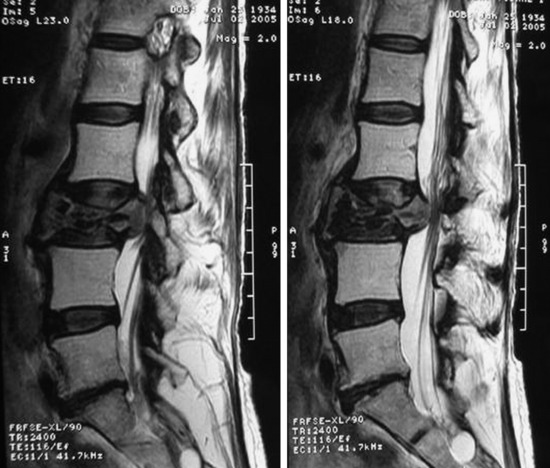
Characteristics of Malignant Spine Fracture in MRI Finding8
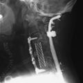
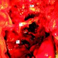
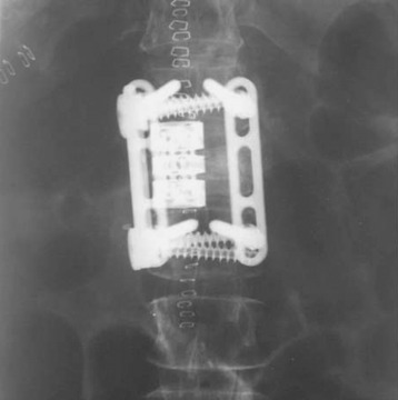
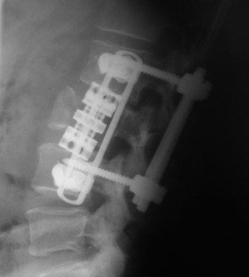
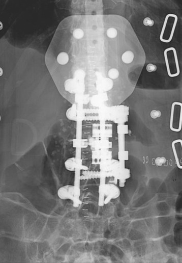
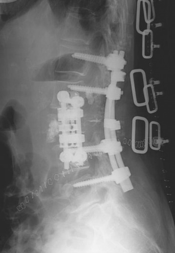
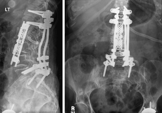
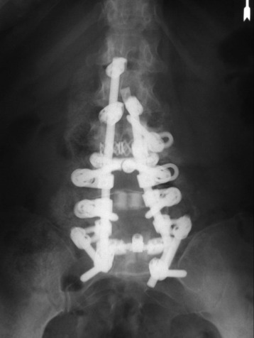
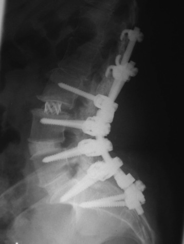
The operation was performed circumferentially. First, posterior decompression and stabilization were performed with a pedicle screw system (Figs. 39-12 and 39-13). Pedicle screws were fixed at L1, L2, L4, and L5. Next, anterior decompression was performed with the retroperitoneal approach. Ventral dura was confirmed after the corpectomy. The anterior shell of the L3 body was left. The vertebral body replacement cage was inserted into the corpectomy site. Anterior stabilization was performed with a screw and rod system. When the screw was inserted, the direction was adjusted to avoid meeting the pedicle screws. If the vertebral body and posterior element are removed altogether, the stabilization should be circumferentially, and the posterior stabilization should be performed at least two levels above and two levels below. When the rod is applied, the lumbar lordotic curve should be considered. The pathological diagnosis was plasmacytoma.
With regard to solitary plasmacytoma, the surgical indication is related to the tumor progression in connection with threatening neurological complications by spinal cord compression. According to the literature,9 stabilizing procedures from dorsal as well as ventral procedures also are described near the exclusive spinal decompression. In such a case, an operation combined with an adjuvant treatment is necessary, considering possible long-term survival periods. This principle is applicable to multiple myeloma.
Two-Level Vertebral Body Lesion at L2 and L3
If the vertebral body lesions involve two levels and the posterior elements are intact, the supplementary posterior stabilization with two levels above and two levels below is sufficient. This is a L2, L3 metastatic tumor case (lung carcinoma). The L2 vertebral body signal was changed, and a partial signal change was seen on the anterior half of the L3 body (Figs. 39-14 and 39-15). The L2 and L3 vertebral bodies were removed with the anterior retroperitoneal approach. The vertebral body replacement cage was inserted and the anterior stabilization was performed with the rod and screw system. Pedicle screw fixation was applied to the T12, L1, L5, and S1 levels (Fig. 39-16).
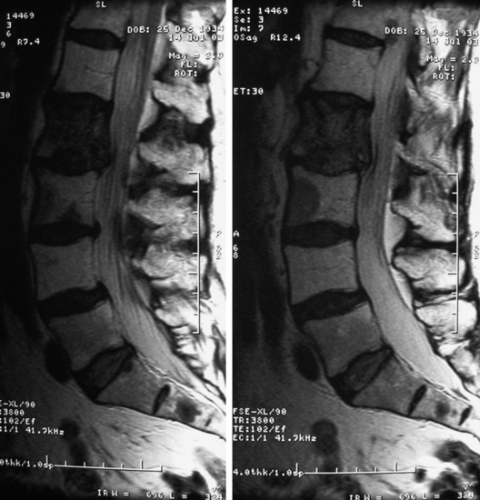
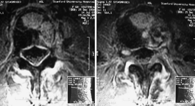
Fig. 39-15 Axial MRI. The tumor mass is seen on the left anterolateral portion of the vertebral body.
SACRAL SCREW FIXATION FOR LUMBOSACRAL STABILIZATION
There are some special considerations with respect to sacral screw fixation. Anatomically iliac wings block the ideal trajectory of the sacral screw. When bicortical purchase is attempted, vascular injury may be significant. In unicortical purchase, resultant fixation may be poor. For lumbosacral junction stabilization, an S1 screw is usually used. The increased size of sacral pedicles compared with lumbar pedicles requires larger-diameter pedicle screws for stable purchase. Although S1 pedicle screws are suitable for short constructs, long constructs result in increased pullout stress on these screws. In these cases, multiple fixation points are necessary. A second point of sacral fixation has significant mechanical advantages compared with only one sacral fixation point. The S2 pedicle and iliac bone can be candidates for a second point of fixation. Iliac fixation is most effective in reducing S1 screw strain10 and is least likely to fail. With the S2 pedicle screw, the power of stabilization remains nearly the same, irrespective of the direction of screw insertion.
S1 SCREW FIXATION
Anteromedial Direction to Sacral Promontory
The entry point for the first sacral pedicle is located at the inferolateral portion of the L5–S1 facet (Fig. 39-17).1 After the soft tissue is stripped away, an elevated bony ridge is seen.
Fluoroscopy is used to confirm correct entry sites. The outlet view is preferable during intraoperative fluoroscopy for sacral pedicle screw placement because it provides the best possible radiographic definition of the sacral neural foramen. It is taken with the pelvis supine and the x-ray beam angled 40 to 50 degrees cephalad. The cortical bone is cut away and the pedicle probe is inserted toward the sacral promontory with a medial inclination of 20–30 degrees. If bicortical purchase is attempted, a smooth Steinmann pin is used with gentle mallet blows to penetrate the anterior cortex. No more than 2-mm overpenetration is tolerated.11
Anterolateral Direction to Sacral Ala
The entry point is slightly lower or distal to that of the medially directed S1 screw and is located in the depression just inferior to the infrafacetal crest (Fig. 39-18). The angle of insertion is 30–35 degrees laterally and parallel to the sacral endplate.12
Iliosacral Screw
The iliosacral screw is inserted from the ilium into the sacral body or the ala. One study showed that iliosacral screws were biomechanically superior and significantly increased mechanical stiffness to flexion mode compared with sacral screws.10
The mean S1 pedicle axis length—the distance between the outer table of the ilium and anterior cortex of the sacrum—is measured to be 92–112 mm in a cadaver study.13
The S1 pedicular axis is 20–43 mm (mean value, 32 mm) from the posterior limit of the ilium (Figs. 39-19 and 39-20). The axial plane is the same with the conventional S1 promontory screw.
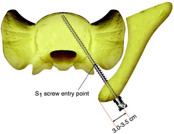
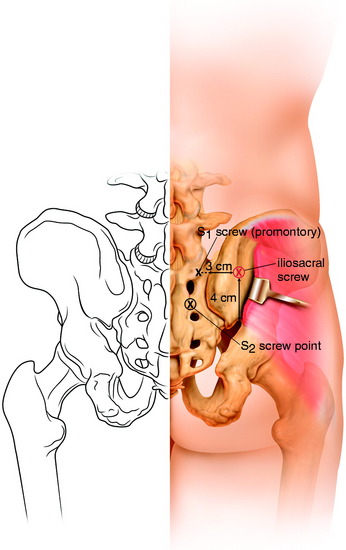
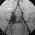
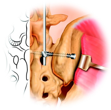
The sacrum is exposed from the midline to the posterior iliac bone bilaterally. The conventional S1 screw entry point is marked on the inferolateral point of the L5–S1 facet joint. The outer wing of the posterior iliac bone is exposed subperiosteally. The entry point is marked 3 cm from the posterior limit of the iliac crest in the sagittal plane. The point is 3.5–4 cm cephalad to the greater sciatic notch (see Figs. 39-19 and 39-20). The screw is inserted at a perpendicular angle into the S1 pedicular axis. For the connection of the iliosacral screw with the lumbosacral rod, the specially designed connector is used (Fig. 39-21).
S2 SCREW FIXATION
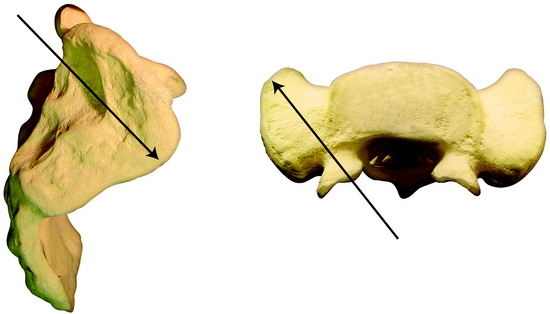
For the S2 screw, both the S1 and S2 dorsal foramen are exposed. The entry point for the S2 screw is the midpoint between the S1 and S2 dorsal foramen (see Fig. 39-20). The S2 screw directs the awl/probe cephalad and lateral into the inferolateral corner of the sacral ala. The cross-sectional configuration of S2 presents in the shape of a butterfly (Fig. 39-22). The angles approximated by the guide are 25 degrees lateral and 45 degrees cephalad (Figs. 39-23 and 39-24).
In the operative field, the head of the S1 screw directs to cephalad and the head of the S2 screw to caudad (Fig. 39-25). Cantilever forces can be high because of the lumbosacral kyphotic angle, especially in a long construct that extends over the thoracolumbar junction. Instrumentation with a significant preload or large cantilever forces may require additional fixation points (e.g., iliac bone).
NEURAL STRUCTURES AROUND S1, S2 PEDICLE
The mean distance from the reference point to the adjacent nerve roots superiorly and inferiorly at the S2 pedicle level was smaller than those at the S1 pedicle level. The medial angle of the sacral nerve roots progressively decreases from L5 to S3.13 The nerve root passing through the next foramen forms an immediate medial relation to the sacral pedicle rather than the dural sac. Violation of the sacral canal and foramina by a sacral pedicle screw may injure the sacral nerve roots, especially at the level of the S2 pedicle.