Chapter 167 Percutaneous Placement of Lumbar Pedicle Screws
Indications and Techniques
Introduction
The use of pedicle screws for spinal stabilization has become increasingly popular worldwide. Pedicle screw systems engage all three columns of the spine and can resist motion in all planes. Several studies suggest that pedicle screw fixation is a safe and effective treatment for many spinal disorders.1,2 Standard techniques for pedicle screw placement, however, require extensive tissue dissection to expose entry points and to provide a lateromedial orientation for optimal screw trajectory. Open pedicle fixation and spinal fusion have been associated with extensive blood loss, lengthy hospital stays, and significant cost.3 Minimally invasive placement of pedicle screws can potentially address these issues without compromising the accuracy of placement.4
The use of percutaneous lumbar pedicle screws and an interconnecting subfascial rod was first described in 20015 and later adopted by others.6,7 The spinal implants used for percutaneous pedicle screw fixation are essentially the same as those used in conventional open techniques. To preserve soft tissue and allow for safe and effective insertion of these implants into the lumbar spine, certain principles need to be followed. For example, the pedicle screws are commonly placed over K-wires. These allow the surgeon to gain access to a pedicle pilot hole with minimal, if any, direct visualization. Screw extenders, which allow for percutaneous manipulation and localization of the screws once they have been inserted and cannot be seen directly by the surgeon, also provide a means for screw alignment so that an interconnecting rod can be successfully joined to the screws in a minimally invasive fashion. This chapter describes techniques for percutaneous lumbar pedicle screw fixation and the present related outcome data.
Operative Techniques
Patient Positioning and Operating Room Setup
Percutaneous pedicle fixation of the lumbar spine can be performed after induction of general or epidural anesthesia. Thereafter the patient is positioned prone on top of a radiolucent spinal surgery table with the abdomen free. Chest rolls on a radiolucent flattop or Jackson-type frame can be used for this purpose. For guidance during percutaneous screw placement, options include conventional fluoroscopy, virtual fluoroscopy, or intraoperative CT-based imaging. Regardless of whether one uses conventional or virtual fluoroscopic guidance during the procedure, it is important to check that adequate anteroposterior (AP) and lateral fluoroscopic images of the lumbar spine can be obtained before preparing and draping the patient.
Initial Incision and Pedicle Identification
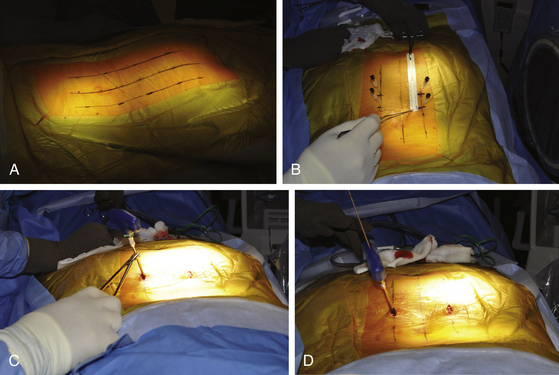
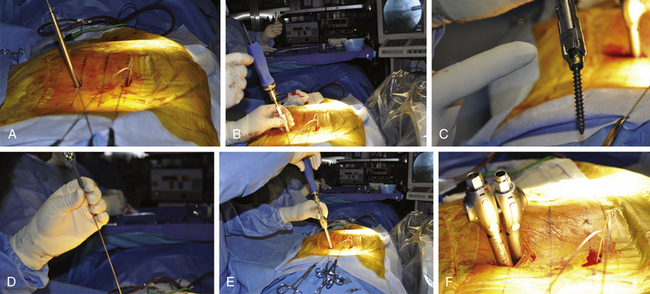
Fluoroscopic images are obtained in the AP and lateral planes to ensure that the pedicles can be adequately visualized. If necessary, oblique (or “owl’s-eye”) views can be obtained as well. It is important that “true” AP and lateral views are obtained because even a minor misalignment in imaging may lead to wayward screw placement. To ensure a true AP view, the spinous process must lie precisely in the center of the interpedicular space. To obtain a true lateral view, the pedicles should overlie one another and the end plates should be linear (not elliptical). If the patient is scoliotic, the C-arm should be angled to achieve these views. Furthermore, to avoid parallax, center the target anatomy on the fluoroscopic screen. It is therefore important to check the fluoroscopic views before the skin is prepared and the patient is draped. This allows for manipulation and repositioning of the patient, bed, and fluoroscopic C-arm without compromising the sterile field. Additionally, the use of a radiolucent table (e.g., Jackson table) and, if used, a radiolucent positioning device (e.g., gel chest rolls) is important. A small incision is made approximately 4 to 5 cm off the midline, depending on the size of the patient (Fig. 167-1A). For a thin patient, an incision 4 cm off the midline is utilized. A more lateral incision is made for an obese patient. The principle is that a lateromedial trajectory is desired; the object is to maximize the bone purchase of the pedicle screw while avoiding the facet complex. A larger patient, with more soft tissue dorsal to the spine, requires an incision that is farther from the midline to achieve the same trajectory as that for a thinner patient. A 22-gauge spinal needle can be used to localize the position of the incision prior to cutting the skin (Fig. 167-1B). The incision length is dependent on the diameter of screw extenders but is approximately 1.5 cm for a single screw and 2.5 cm for two screws.
Pedicle Screw Placement
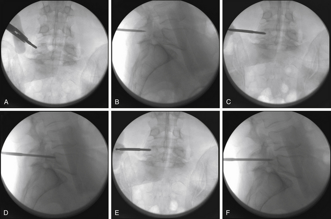
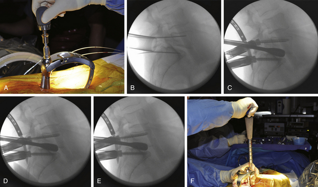
Thorough knowledge of pedicle anatomy and the sagittal and axial angulation of the individual pedicles is mandatory for safe percutaneous screw placement.8 These angles are best judged using preoperative CT or MRI of the lumbar region. The pedicle can be navigated using a conventional C-arm fluoroscope that is alternated between AP, lateral, and oblique views. One must obtain multiple sequential views of the pedicle probe in at least two planes as it is advanced down the pedicle.1,8 It is important to keep these trajectories in mind to ensure the accuracy of percutaneous screw placement. The ideal pedicle entry point is at the base of the transverse process as it joins the superior articular process; this location allows for the lateromedial trajectory of screws and minimizes the anatomic disturbance of the facet joint. One advantage of percutaneous screw placement over the conventional open technique is that it is much easier to achieve the required medial angulation because extensive soft-tissue and muscle retraction is avoided. A Jamshidi-type needle is used to create a pilot hole under fluoroscopic guidance (Fig. 167-1C and D). The needle is advanced through the pedicle into the vertebral body. Fluoroscopic images of three positions of the Jamshidi needle should be obtained: the initial starting point, the middle position within the pedicle, and the position at the pedicle-vertebral body junction. For the initial starting point, the Jamshidi needle should be coaxial with the pedicle on the lateral fluoroscopic image. The starting AP image should reveal the tip of the needle to be at the lateral border of the pedicle (Fig. 167-2A and B). When lateral fluoroscopy shows the tip of the needle has been advanced to the pedicle-vertebral body junction, the AP image should reveal that the Jamshidi needle tip is just lateral to the medial cortical wall of the pedicle, with approximately 4 mm of space to spare (Fig. 167-2C and D). This ensures that there is adequate room for the subsequent placement of a screw (with a radius of approximately 2.75 to 3.75 mm), thus minimizing the potential for medial wall breach and nerve root irritation. The value of obtaining AP and lateral fluoroscopic views of the needle when it has been advanced approximately one half the way down the pedicle is that course adjustments can still be made (Fig. 167-2E and F). If the tip is still close to the lateral cortical wall of the pedicle on the AP view at this point, the needle trajectory needs to be medialized. If the tip is too close to the medial wall, the needle risks penetrating into the canal as it is advanced and its course needs to be lateralized. Although the surgeon can remove the needle from the pedicle and start over, it is often more efficient to steer the needle tip within bone by switching the needle trochar from a pointed tip to a beveled tip (leaving the needle hub in place). If the bevel is placed in a lateral position, a force vector will push the tip of the needle in a medial direction as it is advanced. In similar fashion, medial placement of the bevel will cause the needle tip to be deflected laterally as it is advanced. Once the needle has been confirmed to be in an acceptable position on the AP and lateral fluoroscopic views at the pedicle-vertebral body junction, the needle is advanced into the vertebral body. A K-wire is inserted through the needle into the cancellous bone of the vertebral body, and the needle is withdrawn (Fig. 167-2D). This K-wire will serve as a “switching stick” for subsequent placement of a tap and screw down the same pedicle pilot hole trajectory (Fig. 167-3).
Rod Placement
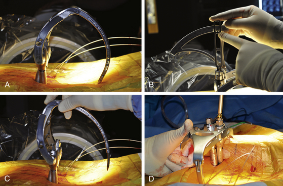
Different instrumentation systems allow various ways of introducing and securing the rod to the screw heads. All systems rely on the principle of using screw extenders, which allow the screws to be manipulated and aligned once they have been inserted (even though the surgeon can no longer see the screw heads). When the screws have been properly aligned, a rod can be inserted and connected to the screws (Fig. 167-4). For percutaneous screw placement, it is essential to know with certainty that the screw heads have captured the rod. Each instrumentation system has its way of determining this (for example, a gauge can be inserted through the extender to confirm the presence of a rod within the screw head). Further confirmation of proper rod capture can be performed using AP and lateral fluoroscopy. Once the rod has been properly delivered to the screw heads, but prior to final tightening, appropriate forces can be applied to the construct (e.g., distraction or compression). This includes the ability to apply reduction forces for minimally invasive correction of spondylolisthesis and other deformities.
Outcomes
Outcome Assessment
Pain and functional disability were quantitatively measured using a Visual Analogue Scale (VAS) and the Oswestry Disability Index (ODI). The VAS scores were recorded on a 100-mm horizontal line, with 0 equal to “no pain” and 100 equal to “very severe pain.” The ODI was recorded on a 0 to 100 scale using the Oswestry Low Back Pain Disability Questionnaire. On this scale, 0% to 20% equates to minimal disability, 20% to 40% to moderate disability, 40% to 60% to severe disability, 60% to 80% to crippled, and 80% to 100% to bed-bound or exaggerating symptoms. Both the VAS and the ODI data were prospectively acquired.
Surgical Technique
Once adequate decompression was obtained, a complete discectomy was performed. If the disc space was collapsed, a small osteotome was then employed to further open the disc space so that sequential intervertebral distractors could be used to restore disc height. Of note, distraction of the disc space often resulted in some measure of spondylolisthesis reduction (Fig. 167-5).9
Attention was then turned to the ipsilateral side, where the intervertebral distractor was removed. Distraction was maintained by the contralateral pedicle screw and rod construct. The empty disc space was filled initially with recombinant human bone morphogenetic protein 2 (rhBMP-2) soaked in collagen sponge carrier as well as local autograft, leaving a channel for an interbody implant. An appropriately sized polyetheretherketone (PEEK) interbody implant was selected and filled with rhBMP-2 and autograft. Because of the oblique trajectory afforded by the starting 4 to 4.5 cm off the midline, the interbody implant could be placed so as to cross the midline of the disc space. Ipsilateral screws were then placed as described above.
Results
We were able to address spondylolisthesis in a series of 40 consecutive patients with percutaneous pedicle screw placement with a mean follow-up of 35 months (range from 24 to 60 months; see Table 167-1). Thirty patients had degenerative spondylolisthesis, and ten had isthmic spondylolisthesis. Thirty-two were evaluated as Meyerding grade I and eight were evaluated as Meyerding grade II. The majority of cases occurred at L4-L5 (n = 28). Others occurred at L5-S1 (n = 8), L3-L4 (n = 2), and L4-S1 (n = 2). Bilateral percutaneous fixation was performed in all cases (Sextant), and none were converted to open surgery.
| Variables | Data |
|---|---|
| Total patients | 40 |
| Mean age (range) | 56 years (38 to 71 years) |
| Sex, n (%) | |
| M | 21 (52.5) |
| F | 19 (47.5) |
| Meyerding grade, n (%) | |
| I | 32 (80) |
| II | 8 (20) |
| Mean reduction | 76% |
| Mean follow-up (range) | 35 months (24 to 60 months) |
| Leg pain | |
| Mean preoperative VAS score (range) | 65 (9 to 99) |
| Mean postoperative VAS score (range) | 8 (0 to 22) |
| Back pain | |
| Mean preoperative VAS score (range) | 52 (0 to 97) |
| Mean preoperative VAS score (range) | 15 (0 to 36) |
| Oswestry Disability Index | |
| Mean preoperative score (range) | 55 (44 to 80) |
| Mean postoperative score (range) | 16 (2 to 38) |
VAS, Visual Analogue Scale.
Case
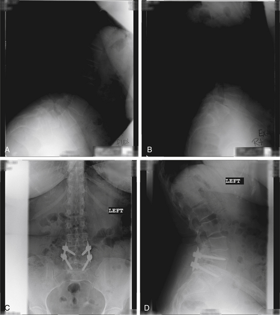
In the case of a 63-year-old patient with bilateral L5 radiculopathy and mechanical low-back pain, we observed near-grade III spondylolisthesis of L4 and L5 on flexion-extension lateral x-rays (Fig. 167-6A and B). A MIS-TLIF procedure at L4 and L5 was performed with a PEEK cage and bone morphogenetic protein with spondylolisthesis reduction by percutaneous screw placement as described above. Postoperative AP and lateral radiographs revealed complete reduction of the spondylolisthesis and good positioning of hardware with the formation of fusion mass across the interbody space (Fig. 167-6C and D). A photograph of the patient’s incisions is shown in Figure 6E. A 1-year postoperative assessment revealed complete resolution of leg and back pain symptoms and resumption of normal daily activity.
Discussion
Percutaneous fixation of the lumbar spine was first described by Magerl,10 who used an external fixator. Mathews et al.11,12 first described and performed a wholly percutaneous lumbar pedicle fixation technique in which they used subcutaneous plates as the longitudinal connectors. Lowery and Kulkarni11 subsequently described a similar technique in which subcutaneous rods were placed. Although the latter authors reported a high success rate, Mathews and Long noted a significant rate of nonunion (H. H. Mathews, personal communication, 2001). In all cases, the longitudinal connectors were placed either externally10 or superficially, just beneath the skin.11,12 This technique has several potential disadvantages. First, the superficial hardware can be irritating and requires routine removal.11 Second, longer screws (and thus longer moment arms) are required, producing less effective biomechanical stabilization than that achieved using standard pedicle fixation systems and leading to a higher potential for implant failure. The use of a percutaneous system has several distinct advantages over conventional pedicle screw fixation. The system eliminates the need for a large midline incision and significant paraspinous muscle dissection. Both the pedicle screws and rod are placed through stab incisions.
The paraspinous muscles are bluntly split rather than divided, leading to potentially shorter periods of hospitalization and recovery.13 Blood loss and tissue trauma are minimized. An ideal lateromedial screw trajectory is much more easily accomplished, especially in larger patients, because significant paraspinous tissue retraction is avoided. This procedure also allows the screws and rods to be placed in a standard anatomic position. This optimizes the biomechanics of the fixation and allows the hardware to remain in place without irritating the superficial tissues of the low back and thus obviates routine hardware removal. The goal of these surgeries, as is true for all minimally invasive procedures, is to minimize approach-related morbidity while achieving the same result as that realized with the use of more traditional, invasive approaches. The percutaneous pedicle screw technique follows the same principles, allowing the surgeon to perform biomechanically sound internal spinal fixation with minimal tissue trauma. Coupled with techniques for minimally invasive spinal fusion and decompression,2 the utility of percutaneous lumbar pedicle fixation should widen.
Foley K.T., Gupta S.K., Justis J.R., Sherman M.C. Percutaneous pedicle screw fixation of the lumbar spine. Neurosurg Focus. 2001;10:E10.
Foley K.T., Smith M.M., Rampersaud Y.R. Microendoscopic approach to far-lateral lumbar disc herniation. Neurosurg Focus. 1999;7:e5.
Gaines R.W.Jr. The use of pedicle-screw internal fixation for the operative treatment of spinal disorders. J Bone Joint Surg Am. 2000:1458-1476. 82-A
Khoo L.T., Palmer S., Laich D.T., Fessler R.G. Minimally invasive percutaneous posterior lumbar interbody fusion. Neurosurgery. 2002;51(suppl 2):S166-S181.
Lee S.-H., Choi W.-G., Lim S.-R., et al. Minimally invasive anterior lumbar interbody fusion followed by percutaneous pedicle screw fixation for isthmic spondylolisthesis. Spine J. 2004;4:644-649.
Lowery G.L., Kulkarni S.S. Posterior percutaneous spine instrumentation. Eur Spine J. 2000;9(suppl 1):S126-S130.
Magerl F. External skeletal fixation of the lower thoracic and the lumbar spine. In: Uhthoff H., Stahl E. Current Concepts of External Fixation of Fractures. New York, NY: Springer-Verlag; 1982:353-356.
Mathews H.H., Evans M.T., Molligan H.J., Long B.H. Laparoscopic discectomy with anterior lumbar interbody fusion: a preliminary review. Spine (Phila Pa 1976). 1995;20:1797-1802.
Mummaneni P.V., Rodts G.E.Jr. The mini-open transforaminal lumbar interbody fusion. Neurosurgery. 2005;57:256-261. discussion 256–261
Schizas C., Michel J., Kosmopoulos V., Theumann N. Computer tomography assessment of pedicle screw insertion in percutaneous posterior transpedicular stabilization. Eur Spine J. 2007;16:613-617.
Thomsen K., Christensen F.B., Eiskjær S.P., et al. 1997 Volvo Award winner in clinical studies. The effect of pedicle screw instrumentation on functional outcome and fusion rates in posterolateral lumbar spinal fusion: a prospective, randomized clinical study. Spine (Phila Pa 1976). 1997;22:2813-2822.
Wiesner L., Kothe R., Rüther W. Anatomic evaluation of two different techniques for the percutaneous insertion of pedicle screws in the lumbar spine. Spine (Phila Pa 1976). 1999;24:1599-1603.
Yuan H.A., Garfin S.R., Dickman C.A., Mardjetko S.M. A historical cohort study of pedicle screw fixation in thoracic, lumbar, and sacral spinal fusions. Spine (Phila Pa 1976). 1994;19(suppl 20):2279S-2296S.
1. Gaines R.W.Jr. The use of pedicle-screw internal fixation for the operative treatment of spinal disorders. J Bone Joint Surg Am. 2000:1458-1476. 82-A
2. Yuan H.A., Garfin S.R., Dickman C.A., Mardjetko S.M. A historical cohort study of pedicle screw fixation in thoracic, lumbar, and sacral spinal fusions. Spine (Phila Pa 1976). 1994;19(suppl 20):2279S-2296S.
3. Thomsen K., Christensen F.B., Eiskjær S.P., et al. 1997 Volvo Award winner in clinical studies. The effect of pedicle screw instrumentation on functional outcome and fusion rates in posterolateral lumbar spinal fusion: a prospective, randomized clinical study. Spine (Phila Pa 1976). 1997;22:2813-2822.
4. Schizas C., Michel J., Kosmopoulos V., Theumann N. Computer tomography assessment of pedicle screw insertion in percutaneous posterior transpedicular stabilization. Eur Spine J. 2007;16:613-617.
5. Foley K.T., Gupta S.K., Justis J.R., Sherman M.C. Percutaneous pedicle screw fixation of the lumbar spine. Neurosurg Focus. 2001;10:E10.
6. Khoo L.T., Palmer S., Laich D.T., Fessler R.G. Minimally invasive percutaneous posterior lumbar interbody fusion. Neurosurgery. 2002;51(suppl 2):S166-161.
7. Lee S.-H., Choi W.-G., Lim S.-R., et al. Minimally invasive anterior lumbar interbody fusion followed by percutaneous pedicle screw fixation for isthmic spondylolisthesis. Spine J. 2004;4:644-649.
8. Wiesner L., Kothe R., Rüther W. Anatomic evaluation of two different techniques for the percutaneous insertion of pedicle screws in the lumbar spine. Spine (Phila Pa 1976). 1999;24:1599-1603.
9. Mummaneni P.V., Rodts G.E.Jr. The mini-open transforaminal lumbar interbody fusion. Neurosurgery. 2005;57(suppl 4):256-261.
10. Magerl F. External skeletal fixation of the lower thoracic and the lumbar spine. In: Uhthoff H., Stahl E. Current Concepts of External Fixation of Fractures. New York, NY: Springer-Verlag; 1982:353-356.
11. Mathews H.H., Long B.H. Endoscopy assisted percutaneous anterior interbody fusion with subcutaneous suprafascial internal fixation: evolution of technique and surgical considerations. Orthop Int Ed. 1995;3:496-500.
12. Lowery G.L., Kulkarni S.S. Posterior percutaneous spine instrumentation. Eur Spine J. 2000;9(suppl 1):S126-S130.
13. Foley K.T., Smith M.M., Rampersaud Y.R. Microendoscopic approach to far-lateral lumbar disc herniation. Neurosurg Focus. 1999;7:e5.