Particle size reduction and size separation
Michael E. Aulton and John N. Staniforth
Chapter contents
Introduction to size reduction
Influence of material properties on size reduction
Crack propagation and toughness
Energy requirements of size reduction process
Influence of size reduction on size distribution
Combined impact and attrition methods
Selection of particle size reduction method
Introduction to size separation
Size separation by sedimentation
Size separation by elutriation
Key points
Introduction to size reduction
The significance of particle size in drug delivery has been discussed in Chapter 9 and some of the reasons for carrying out a size reduction operation have already been noted. In addition, the function of size reduction (also called comminution) may be to aid efficient processing of solid particles by facilitating powder mixing or the production of suspensions. There are also some special functions of size reduction, such as exposing cells in plant tissue prior to extraction of the active principles or reducing the bulk volume of a material to improve transportation efficiency.
Influence of material properties on size reduction
Crack propagation and toughness
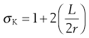
Size reduction or comminution is carried out by a process of crack propagation, whereby localized stresses produce strains in the particles that are large enough to cause bond rupture and thus propagate the crack. In general, cracks are propagated through regions of a material that possess the most flaws or discontinuities. Crack propagation is related to the strain energy in specific regions according to Griffith’s theory. The stress in a material is concentrated at the tip of a crack and the stress multiplier can be calculated from an equation developed by Inglis:
 (10.1)
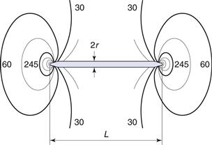
where σK is the multiplier of the mean stress in a material around a crack, L is the length of the crack and r is the radius of curvature of the tip of the crack. For a simple geometric structure such as a circular discontinuity L = 2r and the stress multiplier σK will have a value of 3.
In the case of a thin disc-shaped crack, shown in cross-section in Figure 10.1, the crack is considered to have occurred at molecular level between atomic surfaces separated by a distance of 2 × 10⁻¹⁰ m for a crack 3 µm long, which gives a stress multiplier of approximately 245. The stress concentration diminishes towards the mean stress according to the distance from the crack tip (Fig. 10.1). Once a crack is initiated, the crack tip propagates at a velocity approaching 40% of the speed of sound in the solid. This crack propagation is so rapid that excess energy from strain relaxation is dissipated through the material and concentrates at other discontinuities, where new cracks are propagated. Thus a cascade effect occurs and almost instantaneous brittle fracture occurs.
Not all materials exhibit this type of brittle behaviour and some can resist fracture at much larger stresses. This occurs because these tougher materials can undergo plastic flow, which allows strain energy relaxation without crack propagation. When plastic flow occurs, atoms or molecules slip over one another and this process of deformation requires energy. Brittle materials can also exhibit plastic flow and Irwin and Orowan suggested a modification of Griffiths’ crack theory to take this into account. This relationship has a fracture stress, σ, which varies inversely with the square root of crack length, L:
 (10.2)
where Ep is the energy required to form unit area of double surface.
It can therefore be seen that the ease of comminution depends on the brittleness or plasticity of the material because of their relationship with crack initiation and crack propagation.
Surface hardness
In addition to the toughness of the material described above, size reduction may also be influenced by the hardness of the material. Hardness can be described empirically by its position in a scale devised by a German mineralogist called Mohs. Mohs’ scale is a table of minerals; at the top of the table is diamond, with Mohs hardness >7, and this has a surface that is so hard that it can scratch anything below it. At the bottom of the table is talc, with Mohs hardness <3, and this is soft enough to be scratched by anything above it.
A quantitative measurement of surface hardness was devised by Brinell. This involves placing a hard spherical indenter (e.g. hardened steel or sapphire) in contact with the test surface and applying a known constant load to the sphere. The indenter will penetrate into the surface until and when the sphere is removed, the permanent deformation of the sample is measured. From this, the hardness of the material can be calculated. Hardness has the dimensions of stress (force applied to the indenter divided by the area of test material that will support the load, example units are MPa). A similar Vickers hardness test employs a square-pyramidal diamond as the indenter tip.
Such determinations of hardness are useful as a guide to the ease with which size reduction can be carried out because, while it appears to be a surface assessment, the test actually quantifies the deformation characteristics of the bulk solid. In general, harder materials are more difficult to comminute and can lead to abrasive wear of metal mill parts, which can then result in product contamination. Conversely, materials with a large elastic component, such as rubber, are extremely soft yet difficult to size reduce.
Materials such as rubber that are soft under ambient conditions, waxy substances such as stearic acid that soften when heated, and ‘sticky’ materials such as gums are capable of absorbing large amounts of energy through elastic and plastic deformation without crack initiation and propagation. This type of material, which resists comminution at ambient or elevated temperatures, can be more easily size reduced when temperatures are lowered below the glass transition point of the material. At these lower temperatures the material undergoes a transition from plastic to brittle behaviour and crack propagation is facilitated.
Other factors that influence the process of size reduction include the moisture content of the material. In general, a material with a moisture content below 5% is suitable for dry grinding and one with greater than 50% will generally require wet grinding to be carried out.
Energy requirements of size reduction process
Only a very small amount of the energy put into a comminution operation actually effects size reduction. This has been estimated to be as little as 2% of the total energy consumption, the remainder being lost in many ways, including:
• elastic deformation of particles
• plastic deformation of particles without fracture
• deformation to initiate cracks that cause fracture
• deformation of metal machine parts
• particle–machine wall friction
• heat
• sound
A number of hypotheses and theories have been proposed in an attempt to relate energy input to the degree of size reduction produced.
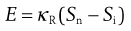
Rittinger’s hypothesis relates the energy, E, used in a size reduction process to the new surface area produced, Sn, or:
 (10.3)
where Si is the initial surface area and κR is Rittinger’s constant, expressing energy per unit area.
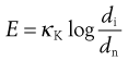
Kick’s theory states that the energy used in deforming or fracturing a set of particles of equivalent shape is proportional to the ratio of the change in size, or:
 (10.4)
where κK is Kick’s constant of energy per unit mass, di is the initial particle diameter and dn the new particle diameter.
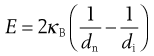
Bond’s theory states that the energy used in crack propagation is proportional to the new crack length produced, which is often related to the change in particle dimensions according to the following equation:
 (10.5)
Here κB is known as Bond’s work index and represents the variation in material properties and size reduction methods, with dimensions of energy per unit mass.
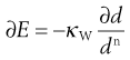
Walker proposed a generalized differential form of the energy–size relationship that can be shown to link the theories of Rittinger and Kick, and in some cases that of Bond:
 (10.6)
where κW is Walker’s constant and d is a size function that can be characterized by an integrated mean size or by a weight function, n is an exponent. When n = 1 for particles defined by a weight function, integration of Walker’s equation corresponds to a Kick-type theory, when n = 2 a Rittinger-type solution results and when n = 1.5 Bond’s theory is given.
When designing a milling process for a given particle, the most appropriate energy relationship will be required in order to calculate energy consumptions. It has been considered that the most appropriate values for n are 1 for particles larger than 1 µm where Kick-type behaviour occurs, and 2 for Rittinger-type milling of smaller particles of less than 1 µm. The third value of n = 1.5 is the average of these two extremes and indicates a possible solution where neither Kick’s nor Rittinger’s theory is appropriate. Other workers have found that n cannot be assumed to be constant, but varies with particle size.
Influence of size reduction on size distribution
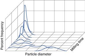
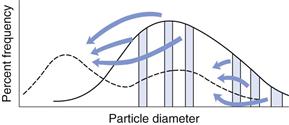
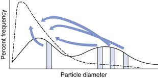
In Chapter 9, several different size distributions were discussed and some were based on either a normal or a log-normal distribution of particle sizes. During a size reduction process the particles of feed material will be broken down and particles in different size ranges undergo different amounts of breakage. This uneven milling leads to a change in the size distribution, which is superimposed on the general movement of the normal or log-normal curve towards smaller particle diameters. Changes in size distributions that occur as milling proceeds have been demonstrated experimentally and this showed that an initial normal particle size distribution was transformed through a size-reduced bimodal population into a much finer powder with a positively skewed, leptokurtic particle population (Fig. 10.2) as milling continued. The initial, approximately normal, size distribution was transformed into a size-reduced bimodal population through differences in the fracture behaviour of coarse and fine particles (Fig. 10.3). If milling is continued a unimodal population reappears, as the energy input is not great enough to cause further fracture of the finest particle fraction (Fig. 10.4).
The lower particle size limit of a milling operation is dependent on the energy input and on material properties. With particle diameters below approximately 5 µm, interactive cohesive forces between the particles generally predominate over comminution stresses as the comminution forces are distributed over increasing surface areas. This eventually results in particle agglomeration as opposed to particle fracture and size reduction ceases. In some cases particle agglomeration occurs to such a degree that subsequent milling actually causes size enlargement.
Size reduction methods
There are many different types of size reduction techniques and the apparatus available for size reduction of pharmaceutical powders continues to develop. This chapter illustrates the principles associated with techniques that are classified according to the milling process employed to subdivide the powder particles. The chapter does not catalogue all existing milling equipment but instead illustrates the various principles involved – examples of each type are given below. The approximate size reduction range achievable with each technique is illustrated, although it should be remembered that the extent of size reduction is always related to milling time.
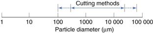
Cutting methods
Size reduction range
This is indicated in Figure 10.5.
Cutter mill
A cutter mill (Fig. 10.6) consists of a series of knives attached to a horizontal rotor which act against a series of stationary knives attached to the mill casing. During milling, size reduction occurs by fracture of particles between the two sets of knives, which have a clearance of a few millimetres. A screen is fitted in the base of the mill casing and acts to retain material in the mill until a sufficient degree of size reduction has been effected, thus it is self-classifying.
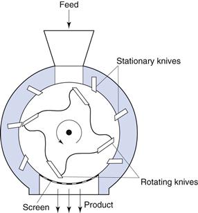
Fig. 10.6 Cutter mill.
The shear rates present in cutter mills are useful in producing a coarse degree of size reduction of dried granulations prior to tableting.
Compression methods
Size reduction range
These are indicated in Figure 10.7.
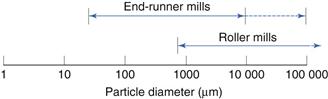
Runner mills
Size reduction by compression can be carried out on a small laboratory scale during development using a mortar and pestle.
Roller mill
A form of compression mill uses two cylindrical rollers mounted horizontally and rotated about their long axes. In roller mills, one of the rollers is driven directly while the second is rotated by friction as material is drawn through the gap between the rollers.
Impact methods
Size reduction range
This is shown in Figure 10.8.
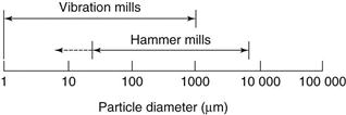
Fig. 10.8 Size reduction range for impact methods.
Hammer mill
Size reduction by impact can be carried out using a hammer mill (Fig. 10.9). Hammer mills consist of a series of four or more hammers, hinged on a central shaft which is enclosed within a rigid metal case. During milling the hammers swing out radially from the rotating central shaft. The angular velocity of the hammers produces a strain rate up to 80 s−1, which is so high that most particles undergo brittle fracture. As size reduction continues, the inertia of particles hitting the hammers reduces markedly (as particle mass is reduced) and subsequent fracture is less probable, so that hammer mills tend to produce powders with narrow size distributions. Particles are retained within the mill by a screen that allows only adequately comminuted particles to pass through. Particles passing through a given mesh can be much finer than the mesh apertures, as particles are carried around the mill by the hammers and approach the mesh tangentially. For this reason, square, rectangular or herringbone slots are often used. Depending on the purpose of the operation, the hammers may be square-faced, tapered to a cutting edge or have a stepped form.
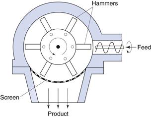
Fig. 10.9 Hammer mill.
Vibration mill
An alternative to hammer milling which produces size reduction is vibration milling (Fig. 10.10). Vibration mills are filled to approximately 80% total volume with porcelain or stainless steel balls. During milling the whole body of the mill is vibrated and size reduction occurs by repeated impact. Comminuted particles fall through a screen at the base of the mill. The efficiency of vibratory milling is greater than that for conventional ball milling described below.
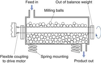
Fig. 10.10 Vibration mill.
Attrition methods
Size reduction range
This is indicated in Figure 10.11.
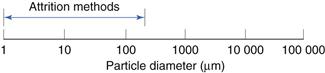
Fig. 10.11 Size reduction range for attrition methods.
Roller mill
Roller mills use the principle of attrition to produce size reduction of solids in suspensions, pastes or ointments. Two or three porcelain or metal rollers are mounted horizontally with an adjustable gap, which can be as small as 20 µm. The rollers rotate at different speeds so that the material is sheared as it passes through the gap and is transferred from the slower to the faster roller, from which it is removed by means of a scraper.
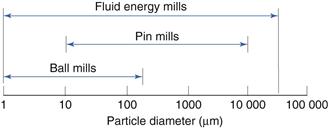
Combined impact and attrition methods
Size reduction range
This is indicated in Figure 10.12.
Ball mill
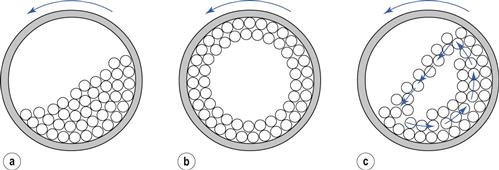
A ball mill is an example of a comminution method which produces size reduction by both impact and attrition of particles. Ball mills consist of a hollow cylinder mounted such that it can be rotated on its horizontal longitudinal axis (Fig. 10.13). The cylinder contains balls that occupy 30–50% of the total volume, the ball size being dependent on feed and mill size. Mills may contain balls with many different diameters as this helps to improve the process, as the large balls tend to break down the coarse feed materials and the smaller balls help to form the fine product by reducing void spaces between balls.
The amount of material in a mill is of considerable importance: too much feed produces a cushioning effect and too little causes loss of efficiency and abrasive wear of the mill parts.
The factor of greatest importance in the operation of the ball mill is the speed of rotation. At low angular velocities (Fig. 10.13a) the balls move with the drum until the force due to gravity exceeds the frictional force of the bed on the drum, and the balls then slide back en masse to the base of the drum. This sequence is repeated, producing very little relative movement of the balls so that size reduction is minimal. At high angular velocities (Fig. 10.13b), the balls are thrown out to the mill wall, where they remain due to centrifugal force and no size reduction occurs. At about two-thirds of the critical angular velocity where centrifuging occurs (Fig. 10.13c), a cascading action is produced. Balls are lifted on the rising side of the drum until their dynamic angle of repose is exceeded. At this point, they fall or roll back to the base of the drum in a cascade across the diameter of the mill. By this means, the most efficient size reduction occurs by impact of the particles with the balls and by attrition. The optimum rate of rotation is dependent on mill diameter but is usually of the order of 0.5 revolutions per second.
Fluid energy mill
Fluid energy milling is another form of size reduction method that acts by particle impaction and attrition. A form of fluid energy or jet mill or micronizer is shown in Figure 10.14. Both circular designs and oval-path designs (as shown in Fig. 10.14) are available. This circular design is now the most common. This consists of a hollow toroid which has a diameter of 20–200 mm. A fluid, usually air, is injected as a high-pressure jet through nozzles at the bottom of the loop. The high velocity of the air gives rise to zones of turbulence into which solid particles are fed. The high kinetic energy of the air causes the particles to impact with other particles and with the sides of the mill with sufficient momentum for fracture to occur. Turbulence ensures that the level of particle–particle collisions is high enough to produce substantial size reduction by impact and some attrition.
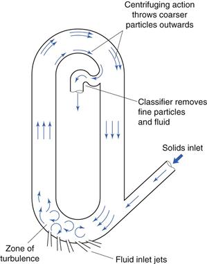
Fig. 10.14 Fluid energy mill.
A particle size classifier is incorporated in the design so that particles are retained in the toroid until sufficiently fine and are then entrained in the air stream that exhausts from the mill
Pin mill
In addition to ball mills and fluid energy mills, there are other methods of comminution that act by producing particle impact and attrition. These include pin mills in which two discs with closely spaced pins rotate against one another at high speeds (Fig. 10.15). Particle size reduction occurs by impaction with the pins and by attrition between pins as the particles travel outwards under the influence of centrifugal force.
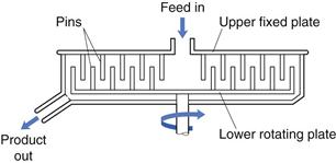
Fig. 10.15 Pin mill.
Selection of particle size reduction method
Different mills can produce differing end product from the same starting material. For example, particle shape may vary according to whether size reduction occurs as a result of impact or attrition. In addition, the proportion of fine particles in the product may vary, so that other properties of the powder will be altered.
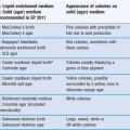
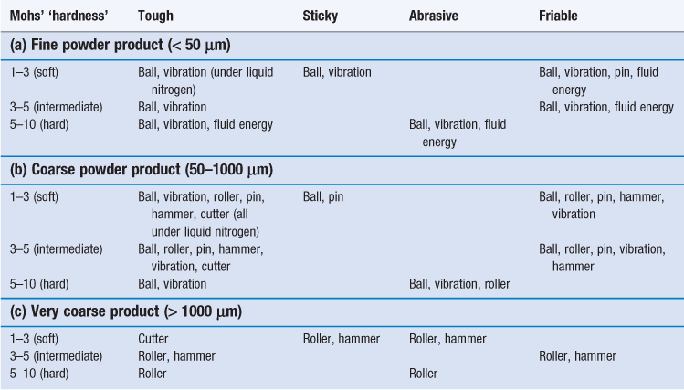
The subsequent usage of a powder usually controls the degree of size reduction needed but in some cases the precise particle size required is not critical. In these circumstances, since the cost of size reduction increases as particle size decreases, it is economically undesirable to mill particles to a finer degree than is necessary. Once the particle size required has been established, the selection of mills capable of producing that size may be modified from knowledge of the particle properties, such as hardness, toughness, etc. The influences of various process and material variables on selection of a size reduction method are summarized in Table 10.1.
Introduction to size separation
Objectives of size separation
The significance of particle size and the principles involved in differentiating a powder into fractions of known particle size and in reducing particle dimensions have been considered in Chapter 9. Methods for achieving the required size range on a manufacturing scale has been discussed above. Here the methods by which size separation can be achieved are discussed.
Solid separation is a process by which powder particles are removed from gases or liquids, and has two main aims:
An important difference exists between the procedures known as size analysis and size separation. The former is designed to provide information on the size characteristics of a powder, whereas the latter is an integral part of a production process and results in a product powder of a given particle size range that is available for separate handling or subsequent processing. Thus, a particle size analysis method such as microscopy would be of no use as a size separation method. However sieving can be used for both purposes.
Size separation efficiency
The efficiency with which a powder can be separated into different particle size ranges is related to the particle and fluid properties and the separation method used. Separation efficiency is determined as a function of the effectiveness of a given process in separating particles into oversize and undersize fractions.
In a continuous size separation process, the production of oversize and undersize powder streams from a single feed stream can be represented by the following equation:
 (10.7)
where fF, fo and fu are functions of the mass flow rates of the feed material, oversize product and undersize product streams, respectively. If the separation process is 100% efficient, then all oversize material will end up in the oversize product stream and all undersize material will end up in the undersize product stream. Invariably, industrial particle separation processes produce an incomplete separation, so that some undersize material is retained in the oversize stream and some oversize material may find its way into the undersize stream.
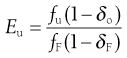
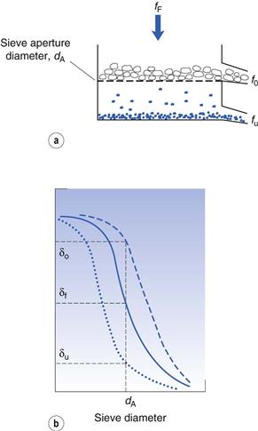
Considering the oversize material, a given powder feed stream will contain a certain proportion of true oversize material, δF; the outgoing oversize product stream will contain a fraction, δo, of true oversize particles, and the undersize product stream will contain a fraction, δu, of true oversize material (Fig. 10.16). The efficiency of the separation of oversize material can be determined by considering the relationship between mass flow rates of feed and product streams and the fractional contributions of true size grade in the streams. For example, the efficiency Eo of a size separation process for oversize material in the oversize stream is given by:
 (10.8)
and the separation efficiency for undersize material in the undersize stream is given by:
 (10.9)
The total efficiency, Et, for the whole size separation process is given by:
 (10.10)
Separation efficiency determination can be applied to each stage of a complete size classification and is often referred to as grade efficiency. In some cases, knowledge of grade efficiency is insufficient, for example where a precise particle size cut is required. A sharpness index can be used to quantify the sharpness of cut-off in a given size range. A sharpness index, S, can be determined in several different ways, for example by taking the percentage values from a grade efficiency curve at the 25% and 75% levels (L25 and L75, respectively):
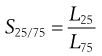 (10.11)
or at other percentile points, for example at the 10% and 90% levels:
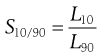 (10.12)
Size separation methods
Some of the types of size separation equipment are discussed briefly below. These have been chosen to illustrate the basic principles of size separation. The actual equipment in use in pharmaceutical processing continues to develop, yet remains based on the principles illustrated.
Size separation by sieving
Principles of operation
The principles of sieving in order to achieve particle size analysis are described in Chapter 9. There are some differences in the methods used to achieve size separation rather than size analysis. The use of sieving in size separation usually requires processing of larger volumes of powder than are commonly found in size analysis operations. For this reason, the sieves used for size separation are often larger in area and of more robust construction than those used for size analysis.
There are several techniques for encouraging particles to separate into their appropriate size fractions efficiently. In dry sieving processes these are based on mechanical disturbances of the powder bed and include the following.
Agitation methods.
Size separation is achieved by electrically induced oscillation, mechanically induced vibration of the sieve meshes or by gyration in which sieves are fitted to a flexible mounting which is connected to an out-of-balance flywheel. In the latter case, the eccentric rotation of the flywheel imparts a rotary movement of small amplitude and high intensity to the sieve and causes the particles to spin, thereby continuously changing their orientation and increasing their potential to pass through a given sieve aperture. The output efficiency of gyratory sieves is usually greater than that of oscillation or vibration methods.
Agitation methods can be made continuous by inclination of the sieve and the use of separate outlets for the undersize and oversize powder streams.
Brushing methods.
A brush is used to reorientate particles on the surface of a sieve and prevent apertures becoming blocked. A single brush can be rotated about the midpoint of a circular sieve or, for large-scale processing, a horizontal cylindrical sieve is employed with a spiral brush rotating about its longitudinal axis. It is important, however, that the brush does not force the particles through the sieve by distorting either the particles or the sieve mesh.
Centrifugal methods.
In this type of equipment, particles are thrown outwards on to a vertical cylindrical sieve under the action of a high-speed rotor inside the cylinder. The current of air created by the rotor movement also assists the sieving process, especially where very fine powders are being processed.
Wet sieving can also be used to effect size separation and is generally more efficient than dry sieving methods.
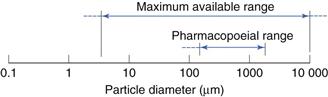
Standards for powders based on sieving
Standards for the size of powders used pharmaceutically are sometimes provided in pharmacopoeias. These may indicate how the degree of coarseness or fineness of a powder is differentiated and expressed by reference to the nominal mesh aperture size of the sieves used. Grades of powder are specified and defined in general terms by most pharmacopoeias. An example is shown in Table 10.2.
Table 10.2
| Description of grade of powder | Coarsest sieve diameter (µm) | Sieve diameter through which no more than 40% of powder must pass (µm) |
| Coarse | 1700 | 355 |
| Moderately coarse | 710 | 250 |
| Moderately fine | 355 | 180 |
| Fine | 180 | – |
| Very fine | 125 | – |
It should be noted that the term ‘sieve number’ has been used as a method of quantifying particle size in pharmacopoeias and is still favoured in some parts of the world. However, various monographs use the term differently and in order to avoid confusion it is strongly recommended to always refer to particle sizes according to the appropriate equivalent diameters expressed in millimetres, micrometres or nanometres, as appropriate.
Size separation by sedimentation
Separation ranges
These are shown in Figure 10.18.
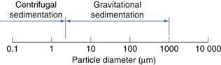
Principles of operation
The principles of particle sizing using sedimentation methods are described in Chapter 9. Size separation by sedimentation utilizes the differences in settling velocities of particles with different diameters, and these can be related according to Stokes’ equations (see Eqns 9.9, 9.10 and 9.11).
One of the simplest forms of sedimentation classification uses a chamber containing a suspension of solid particles in a liquid, which is usually water. After predetermined times, particles less than a given diameter can be recovered from a fixed distance below the surface of the liquid. Size fractions can be collected continuously using a pump mechanism.
Alternatively, a single separation can be carried out simply by removing the upper layer of suspension fluid after the desired time. Disadvantages of these simple methods are that they are batch processes and discrete particle fractions cannot be collected.
Size separation by elutriation
Separation ranges
These are shown in Figure 10.19.
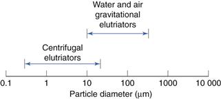
Fig. 10.19 Separation range for elutriation methods.
Principles of operation
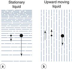
In sedimentation methods the fluid is stationary and the separation of particles of various sizes depends solely on particle velocity. Therefore, the division of particles into size fractions depends on the time of sedimentation.
Elutriation is a technique in which the fluid flows in an opposite direction to the sedimentation movement, so that in gravitational elutriators particles move vertically downwards while the fluid travels vertically upwards. If the upward velocity of the fluid is less than the settling velocity of the particle, sedimentation still occurs and the particles move slowly downwards against the flow of fluid. Conversely, if the upward fluid velocity is greater than the settling velocity of the particle, the particle moves upwards with the fluid flow. Therefore, in the case of elutriation, particles can be divided into different size fractions depending on the velocity of the fluid.
Elutriation and sedimentation methods are compared diagrammatically in Figure 10.20, where the arrows are vectors; that is, they show the direction and magnitude of particle movement. This figure may indicate that if particles are suspended in a fluid moving up a column, there will be a clear cut into two fractions of particle size. In practice this does not occur, as there is a distribution of velocities across the tube in which a fluid is flowing – the highest velocity is found in the centre of the tube and the lowest velocity at the tube walls. Therefore, the size of particles that will be separated depends on their position in the tube: the largest particles in the centre, the smallest towards the outside. In practice, particles may rise with the fluid in the centre of the apparatus and then move outwards to the tube wall, where the velocity is lower and they then fall. A separation into two size fraction occurs, but the size cut is not clearly defined. Assessing the sharpness of size cuts is discussed above.
Separation of powders into several size fractions can be achieved by using a number of elutriators connected in series. The suspension is fed into the bottom of the narrowest column, overflowing from the top into the bottom of the next widest column and so on. Because the mass flow remains the same, as the column diameter increases the fluid velocity decreases and therefore particles of decreasing size will be separated.
Adaptations of this technique in which the liquid is replaced by air are available. Air is used as the counterflow fluid in place of water for elutriation of soluble particles into different size ranges. There are several types of air elutriator, which differ according to the airflow patterns used. An example of an upward airflow elutriator is shown in Figure 10.21. Particles are held on a supporting mesh through which air is drawn. Classification occurs within a very short distance of the mesh and any particles remaining entrained in the air stream are accelerated to a collecting chamber by passage through a conical section of tube. Further separation of any fine particles still entrained in the air flow may be carried out subsequently using different air velocities.

Fig. 10.21 Upward airflow elutriator.
Size separation by cyclone
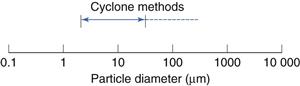
Principles of operation
Probably the most common type of cyclone used to separate particles from fluid streams is the reverse-flow cyclone (Fig. 10.23). In this system, particles in air or liquid suspension are often introduced tangentially into the cylindrical upper section of the cyclone, where the relatively high fluid velocity produces a vortex that throws solid particles out on to the walls of the cyclone. The particles are forced down the conical section of the cyclone under the influence of the fluid flow – gravity interactions are a relatively insignificant mechanism in this process. At the tip of the conical section, the vortex of fluid is above the critical velocity at which it can escape through the narrow outlet and forms an inner vortex which travels back up the cyclone and out through a central outlet or vortex finder. Coarser particles separate from the fluid stream and fall out of the cyclone through the dust outlet, whereas finer particles remain entrained in the fluid stream and leave the cyclone through the vortex finder. In some cases, the outer vortex is allowed to enter a collector connected to the base of the cyclone, but the coarser particles still appear to separate from the fluid stream and remain in the collector. A series of cyclones having different flow rates or different dimensions could be used to separate a powder into different particle size ranges.
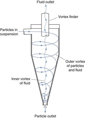
Fig. 10.23 Reverse-flow cyclone separation.
Selection of a size separation process
Selection of a specific size separation method may be limited by pharmacopoeial requirements, but for general cases, the most efficient method should be selected based on particle properties. Of these, size is particularly important, as each separation method is most efficient over a particular size range, as indicated in the foregoing text.
Particles that have just undergone size reduction will already be in suspension in a fluid, whether air or water, and can be separated quickly by elutriation or cyclone separation methods, so that oversize material can be returned to the mill.
Alternatively, many powders used pharmaceutically are soluble in water and size separation may have to be restricted to air classification methods.
Bibliography
1. Allen T. Particle Size Measurement. vols 1 and 2 5th edn London: Chapman and Hall; 1997.
2. Banker GS, Rhodes CT. Modern Pharmaceutics. 4th edn New York: Marcel Dekker; 2002.
3. Gotoh K, Masuda H, Higashitan K. Powder Technology Handbook. 2nd edn New York: Marcel Dekker; 1997.
4. Lachman, L., Lieberman, H.A., Kanig, J.L. (1986) Theory and Practice of Industrial Pharmacy. Lea and Febiger, Philadelphia.
5. Lieberman H, Lachman L, Schwartz JB. Pharmaceutical Dosage Forms: Tablets. vol. 2 2nd edn New York: Marcel Dekker; 1990.
6. Manual on Test Sieving Methods (1972) ASTM Special Technical Publication. American Society for Testing and Materials Standards, Pennsylvania.
7. Niazi SK, ed. Handbook of Pharmaceutical Manufacturing Formulations: vol 2 Uncompressed Solid Products, Part V Powder Flow Properties. Boca Raton, Florida: CRC Press; 2004.
8. Rhodes M, ed. Principles of Powder Technology. New York: John Wiley; 1990.
9. Handbook of Powder Technology. vol. 11. Salmon AD, Hounslow MJ, Seville JPK, eds. 1st edn Amsterdam: Elsevier; 2007.
10. Schweitzer PA, ed. Handbook of Separation Techniques for Chemical Engineers. New York: McGraw-Hill Professional; 1997.
11. Seibert KD, Collins PC, Fisher E. Milling operations in the pharmaceutical industry. In In: am Ende DJ, ed. Chemical Engineering in the Pharmaceutical Industry: R&D to manufacture. New Jersey, USA: John Wiley & Sons; 2010; (in conjunction with AIChE).
12. Svarovsky L. Solid gas separation. In: Handbook of Powder Technology. Amsterdam: Elsevier; 1981;Williams JC, Allen T, eds. Handbook of Powder Technology vol. 3.
13. Swarbrick J, Boylan JC. Encyclopedia of Pharmaceutical Technology. New York: Marcel Dekker; 2002.
14. Wheeler DA. Size reduction. Processing. 1982;Dec:55–58.