[level-membership-for-anesthesiology-category]
Chapter 14 Oxygen Delivery Systems, Inhalation Therapy, and Respiratory Therapy
II Oxygen Therapy
A Indications
O2 is one of the most common therapeutic substances used in the practice of critical care medicine. O2 therapy may improve outcomes of patients undergoing surgery. Use of O2 concentrations greater than 50% FIO2 has reduced the incidence of wound infections in patients undergoing colorectal or spinal surgery.1–4 This section reviews some of the indications, goals, and modes of O2 therapy in the adult patient.
Treatment or prevention of hypoxemia is the most common indication for O2 therapy, and the final goal of effective treatment is avoidance or resolution of tissue hypoxia. Tissue hypoxia exists when delivery of O2 is inadequate to meet the metabolic demands of the tissues. O2 content (Box 14-1) depends on the arterial partial pressure of O2 (PaO2), the hemoglobin concentration of arterial blood, and the saturation of hemoglobin with O2. O2 delivery (DO2) is calculated by multiplying cardiac output (liters per minute) by the arterial O2 content. DO2 is measured in milliliters of O2 per minute, and for a 70-kg, healthy patient, it is approximately 1000 mL/min (Box 14-2).

Box 14-2 Calculation of Oxygen Delivery

CaO2= arterial O2 content per 100 mL of blood mL/dL. This value is approximately 20 mL/dL in the normal adult with a hemoglobin of 15 g/dL.
CO= cardiac output (L/min). This value is approximately 5 L/min in the healthy, 70-kg adult.
DO2= O2 delivery (mL/min). This value is approximately 1000 mL/min in the healthy, 70-kg adult.
 ) and diffusion defect.
 ) is essentially an uncoupling of alveolar blood supply and ventilation. In an area of low
  , hypoxemia results when mixed venous blood flowing past the alveolar-capillary membrane (ACM) takes away O2 molecules faster than ventilation to the alveolus can replace them. The resultant partial pressure of O2 in the alveolus (P
 = 0. Anatomic shunt occurs when blood flows from the right side of the heart to the left side without traversing the pulmonary capillaries. A small percentage of physiologic shunt results from bronchial and thebesian circulation. True intrapulmonary shunts cause hypoxemia that is poorly responsive to O2 therapy. Therapy for “oxygen-refractory” hypoxemia is aimed at reducing the shunt. Different levels of shunting, such as low-ventilation areas, often cause blood to flow through capillaries adjacent to alveoli that do not participate in ventilation. Atelectasis is a common cause of this type of shunt. Respiratory therapy, such as tracheobronchial toilet, to remove mucous plugging of a lobar bronchus or adjusting an endotracheal tube (ETT) that has advanced into a main stem bronchus, may be effective at reversing causes of relative shunt. Positive airway pressure therapy can reduce intrapulmonary shunting in certain disease states associated with a diffuse reduction in functional residual capacity.
 ratio, a portion of ventilation does not participate in gas exchange. Dead space ventilation occurs when the perfusion becomes zero, and the
  ratio approaches infinity. Anatomic dead space is an area of the lungs that does not participate in gas exchange, such as the larger airways. Physiologic dead space is the total dead space that contributes to elevated
  ratio. Dead space ventilation does not contribute significantly to hypoxemia unless perfusion is significantly disrupted, as occurs in a pulmonary embolus.
 mismatch share a common phenomenon, which is exaggerated by a decreased mixed venous hemoglobin saturation (low
  ). Because hemoglobin saturation is the major determinant of O2 content in blood, a low
  leads to a low venous O2 content (
 ). Low
  causes hypoxemia by worsening the hypoxemic effect of any existing shunt or areas of low
  by presenting more desaturated blood to the left atrium. Decreased
  arises from low O2 delivery (e.g., low cardiac output, anemia, hypoxemia) or increased O2 consumption (e.g., high fever, increased minute ventilation and work of breathing).
B Oxygen Delivery Systems
With the exception of anesthetic breathing circuits, virtually all O2 delivery systems are nonrebreathing. In nonrebreathing circuits, the inspiratory gas is not made up in any part by the exhaled tidal volume (VT), and the only CO2 inhaled is that in any entrained room air. To avoid rebreathing, exhaled gases must be sequestered by one-way valves, and inspired gases must be presented in sufficient volume and flow to satisfy the high peak flow rates and minute ventilation demonstrated in critically ill patients. Inspiratory entrainment of room air or the use of inspiratory reservoirs (including the anatomic dead space of the nasopharynx, oropharynx, and non–gas-exchanging portion of the bronchial tree) and one-way valves typifies nonrebreathing systems and defines them as two groups.5–7 Low-flow systems depend on inspiration of room air to meet inspiratory flow and volume demands. High-flow systems attempt to provide the entire inspiratory demand. High-flow systems use reservoirs or very high flow rates to meet the large peak inspiratory flow demands and the exaggerated minute volumes found in many critically ill patients.
1 Low-Flow Oxygen Systems
A low-flow, variable-performance system depends on room air entrainment to meet the patient’s peak inspiratory and minute ventilatory demands that are not met by the inspiratory gas flow or O2 reservoir alone. Low-flow devices include the nasal cannula, simple face mask, partial rebreathing mask, nonrebreathing mask, and tracheostomy collar. Low-flow systems are characterized by the ability to deliver high and low values of FIO2. The FIO2 becomes unpredictable and inconsistent when these devices are used for patients with abnormal or changing ventilatory patterns.8 Low-flow systems produce FIO2 values of 21% to 80%. The FIO2 may vary with the size of the O2 reservoir, O2 flow, and the patient’s ventilatory pattern (e.g., VT, peak inspiratory flow, respiratory rate, minute ventilation). With a normal ventilation pattern, these devices can deliver a relatively predictable and consistent FIO2 level.
The example for estimation of FIO2 from a low-flow system is based on the standard normal patient and ventilatory pattern. Several assumptions are used for the FIO2 calculation. The anatomic reservoir for a nasal cannula consists of nose, nasopharynx, and oropharynx, and it is about one third of the entire normal anatomic dead space (including trachea). For example, 150 mL ÷ 3 = 50 mL; assume a nasal cannula O2 flow rate of 6 L/min (100 mL/sec), VT of 500 mL, respiratory rate of 20 breaths/min, inspiratory (I) time of 1 second, and expiratory (E) time of 2 seconds. If the terminal 0.5 second of the 2-second expiratory time has negligible gas flow, the anatomic reservoir (50 mL) completely fills with 100% O2, assuming an O2 flow rate of 100 mL/sec. Using the preceding normal variables, the FIO2 is calculated for a patient with a 500 mL and a 250 mL VT (Tables 14-1 and 14-2).
| Cannula | 6 L/min | VT, 500 mL |
| Mechanical reservoir | None | I/E ratio = 1 : 2 |
| Anatomic reservoir | 50 mL | Rate = 20 breaths/min |
| 100% O2 provided/sec | 100 mL | Inspiratory time = 1 sec |
| Volume inspired O2 | ||
| Anatomic reservoir | 50 mL | |
| Flow/sec | 100 mL | |
| Inspired room air (0.20 × 350 mL) |
70 mL | |
| O2 inspired | 220 mL | |
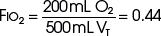 |
FIO2, Fraction of inspired oxygen; I/E ratio, inspiration/expiration ratio; VT, tidal volume.
TABLE 14-2 Example 2: If VT Is Decreased to 250 mL
| Volume inspired O2 | |
| Anatomic reservoir | 50 mL |
| Flow/sec | 100 mL |
| Inspired room air (0.20 × 100 mL) | 20 mL |
| O2 inspired | 170 mL |
 |
FIO2, Fraction of inspired oxygen; VT, tidal volume.
Low-flow O2 devices are the most commonly employed O2 delivery systems because of simplicity, ease of use, familiarity, economics, availability, and acceptance by patients. In most clinical situations (see “High-Flow Oxygen Systems” and “High-Flow Devices”), these systems should be initially employed.
2 High-Flow Oxygen Systems
High-flow, fixed-performance systems are nonrebreathing systems that provide the entire inspiratory atmosphere needed to meet the peak inspiratory flow and minute ventilatory demands of the patient. The flow rate and reservoir are essential to meet the patient’s peak inspiratory flow. Flows of 30 to 40 L/min (or three to four times the measured minute volume) are often necessary. High-flow devices include aerosol masks and T-pieces that are powered by air-entrainment nebulizers or air-O2 blenders and Venturi masks (see “Oxygen Delivery Devices”). Regardless of the patient’s respiratory pattern, high-flow systems are expected to deliver predictable, consistent, and measurable high and low FIO2 values. High-flow systems also can control the humidity and temperature of the delivered gases. The primary limitations of these systems are cost, bulkiness, and patients’ tolerance.
There are two primary indications for high-flow O2 devices:
1. Patients who require a consistent, predictable, minimal FIO2 to reverse hypoxemia but prevent respiratory compromise due to excessive O2 delivery (see “Complications”)
2. The patient with increased minute ventilation and abnormal respiratory pattern who needs predictable and consistent high FIO2 values
C Oxygen Delivery Devices
1 Low-Flow Devices
a Nasal Cannulas
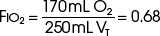
Because of their simplicity and the ease with which patients tolerate them, nasal cannulas are the most frequently used O2 delivery devices. The nasal cannula consists of two prongs, with one inserted into each naris, that deliver 100% O2. To be effective, the nasal passages must be patent, but the patient need not breathe through the nose. The flow rate settings range from 0.25 to 6 L/min. The nasopharynx serves as the O2 reservoir (Fig. 14-1). Gases should be humidified to prevent mucosal drying if the O2 flow exceeds 4 L/min. For each 1 L/min increase in flow, the FIO2 is assumed to increase by 4% (Table 14-3).
| Flow Rate (L/min) | Approximate FIO2* |
|---|---|
| 1 | 0.24 |
| 2 | 0.28 |
| 3 | 0.32 |
| 4 | 0.36 |
| 5 | 0.40 |
| 6 | 0.44 |
FIO2, Fraction of inspired oxygen.
* Based on normal ventilatory patterns.
Avoidance of undue cutaneous pressure is essential. Gauze may be needed to pad pressure points around the cheeks and ears during prolonged use. The flowmeter should be adjusted to the prescribed liter flow to attain the desired FIO2 (see Table 14-3).
Although nasal cannulas are simple and safe, several potential hazards and complications exist. O2 supports combustion, and any type of O2 therapy is a fire hazard. Nasal trauma from prolonged use of or pressure from the nasal prongs can cause tissue damage. With poorly humidified, high gas flows, the airway mucosal surface can become dehydrated. This mucosal dehydration can result in mucosal irritation, epistaxis, laryngitis, ear tenderness, substernal chest pain, and bronchospasm.5,7,9 Because this is a low-flow system, the FIO2 can be inaccurate and inconsistent, leading to the potential for underoxygenation or overoxygenation. Overoxygenation may induce respiratory distress in patients with severe COPD by reversing protective hypoxic pulmonary vasoconstriction, depressing ventilation, and minimizing the Haldane effect (see “Complications”). Underoxygenation potentiates any problems associated with hypoxemia.
b Simple Face Mask
To provide a higher FIO2 value than that provided by nasal cannula with low-flow systems, the size of the O2 reservoir must increase (see Fig. 14-1). A simple face mask consists of a mask with two side ports. The mask serves as an additional O2 reservoir of 100 to 200 mL. The side ports allow room air entrainment and exit for exhaled gases. The mask has no valves. An FIO2 of 0.40 to 0.60 can be achieved predictably when patients exhibit normal respiratory patterns. Gas flows greater than 8 L/min do not significantly increase the FIO2 above 0.60 because the O2 reservoir is filled. A minimum flow of 5 L/min is necessary to prevent CO2 accumulation and rebreathing. The delivered O2 value depends on the ventilatory pattern of the patient, similar to the situation with nasal cannulas.
The equipment needed is identical to that used for nasal cannula O2 administration. The only difference is the use of a face mask. The predicted FIO2 can be estimated from the O2 flow rate (Table 14-4). Appropriate mask application is needed with all masks to maximize the FIO2 and the patient’s comfort. The mask should be positioned over the nasal bridge and the face, restricting O2 escape into the patient’s eye, which can cause ocular drying and irritation. If FIO2 values above 0.60 are required, a partial rebreathing mask, nonrebreathing mask, or high-flow system should be employed. All O2 devices that deliver higher values of FIO2 increase the potential of O2 toxicity (see “Complications”).
| Flow Rate (L/min) | FIO2* |
|---|---|
| 5–6 | 0.4 |
| 6–7 | 0.5 |
| 7–8 | 0.6 |
FIO2, Fraction of inspired oxygen.
c Partial Rebreathing Mask
To deliver an FIO2 level of more than 60% with a low-flow system, the O2 reservoir system must be increased (see Fig. 14-1).7 A partial rebreathing mask adds a reservoir bag with a capacity of 600 to 1000 mL. Side ports allow entrainment of room air and the exit of exhaled gases. The distinctive feature of this mask is that the first 33% of the patient’s exhaled volume fills the reservoir bag. This volume is derived from the anatomic dead space and contains little CO2. During inspiration, the bag should not completely collapse. A deflated reservoir bag results in a decreased FIO2 because of entrained room air. With the next breath, the first exhaled gas (which is in the reservoir bag) and fresh gas are inhaled—accounting for the name partial rebreather. Fresh gas flows should be 8 L/min or greater, and the reservoir bag must remain inflated during the entire ventilatory cycle to ensure the highest FIO2 and adequate CO2 evacuation. An FIO2 of 0.60 to 0.80 or more can be delivered with this device if the mask is applied appropriately and the ventilatory pattern is normal (Table 14-5). This mask’s rebreathing capacity allows O2 conservation and may be useful during transportation, when O2 supply may be limited. Complications with partial rebreathing O2 delivery systems are similar to those with other mask devices with low-flow systems.
TABLE 14-5 Approximate FIO2 Delivered by Mask with Reservoir Bag
| Flow Rate (L/min) | FIO2* |
|---|---|
| 6 | 0.6 |
| 7 | 0.7 |
| 8 | 0.8 |
| 9 | 0.8+ |
| 10 | 0.8+ |
FIO2, Fraction of inspired oxygen.
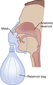
d Nonrebreathing Mask
A nonrebreathing mask (Fig. 14-2) is similar to a partial rebreathing mask but adds three unidirectional valves. One valve is located on each side of the mask to permit the venting of exhaled gases and to prevent room air entrainment. The third unidirectional valve is situated between the mask and the reservoir bag and prevents exhaled gases from entering the bag.
Figure 14-2 A nonrebreathing oxygen mask. In addition to the exhalation valve, the mask has a one-way inhalation valve.
(From Vender JS, Clemency MV: Oxygen delivery systems, inhalation therapy, and respiratory care. In Benumof JL, editor: Clinical procedures in anesthesia and intensive care, Philadelphia, 1992, JB Lippincott.)
2 High-Flow Devices
a Venturi Masks
High-flow systems have flow rates and reservoirs large enough to provide the total inspired gases reliably. Most high-flow systems use gas entrainment at some point in the circuit to provide the flow and FIO2 needs. Venturi masks entrain air by the Bernoulli principle and constant pressure-jet mixing.10 This physical phenomenon is based on a rapid velocity of gas (e.g., O2) moving through a restricted orifice. This action produces viscous shearing forces that create a decreased pressure gradient (subatmospheric) downstream relative to the surrounding gases. The pressure gradient causes room air to be entrained until the pressures are equalized. Figure 14-3 illustrates the Venturi principle.
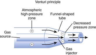
Figure 14-3 Application of the Venturi principle.
(From Vender JS, Clemency MV: Oxygen delivery systems, inhalation therapy, and respiratory care. In Benumof JL, editor: Clinical procedures in anesthesia and intensive care, Philadelphia, 1992, JB Lippincott.)
1. A fixed FIO2 model, which requires specific inspiratory attachments that are color coded and have labeled jets that produce a known FIO2 with a given flow
2. A variable FIO2 model (Fig. 14-4), which has a graded adjustment of the air entrainment port that can be set to allow variation in delivered FIO2
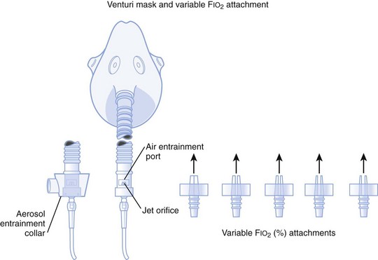
Figure 14-4 Graded air entrainment by the Ventimask provides specific FIO2 levels through the jet orifices.
(From Vender JS, Clemency MV: Oxygen delivery systems, inhalation therapy, and respiratory care. In Benumof JL, editor: Clinical procedures in anesthesia and intensive care, Philadelphia, 1992, JB Lippincott.)
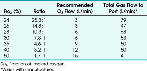
To use any air entrainment device properly to control the FIO2, the standard air-O2 entrainment ratios and minimum recommended flows for a given FIO2 level must be used (Table 14-6). The minimum total flow requirement should result from entrained room air added to the fresh O2 flow and equal three to four times the minute ventilation. This minimal flow is required to meet the patient’s peak inspiratory flow demands. As the desired FIO2 increases, the air-O2 entrainment ratio decreases with a net reduction in total gas flow. The higher the desired FIO2, the greater the probability of the patient’s needs exceeding the total flow capabilities of the device.
Venturi masks are often useful when treating patients with COPD who may develop worsening respiratory distress and dead space ventilation with supplemental increases in O2 fraction.11,12 The Venturi mask’s ability to deliver a high flow with no particulate H2O makes it beneficial in treating asthmatics, in whom bronchospasm may be precipitated or exacerbated by aerosolized H2O administration.
b High-Flow Nasal Cannulas
High-flow nasal cannulas have been developed that can provide humidified gas flows up to 50 L/min while achieving 72% to 100% FIO2.13 Consistent delivery of humidification is also maintained at 72% to 99.9% relative humidity through the use of specialized nasal cannulas,14 larger tubing, high-flow humidifiers, and O2 blenders. These high-flow nasal cannulas can generate moderate levels of continuous positive airway pressure (CPAP) in nasal- and mouth-breathing patients.15 It does not require a face mask, unlike most other high-flow systems, and this affords patients the opportunity to verbally communicate and eat in a normal manner.
c Aerosol Masks and T-Pieces with Nebulizers or Air-Oxygen Blenders
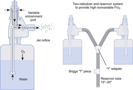
Air entrainment nebulizers can deliver FIO2 of 0.35 to 1.00 and produce an aerosol. The maximum gas flow through the nebulizer is 14 to 16 L/min. As with the Venturi masks, less room air is entrained with higher FIO2 values. As a result, total flow at high FIO2 values is decreased. To meet ventilatory demands, two nebulizers may feed a single mask to increase the total flow, and a short length of corrugated tubing may be added to the aerosol mask side ports to increase the reservoir capacity (Fig. 14-5). If the aerosol mist exiting the mask side ports disappears during inspiration, room air is probably being entrained, and flow should be increased.
D Humidifiers
Room air that has a relative humidity of 50% at 21° C has a relative humidity of 21% at 37° C. Under normal conditions, the lungs contribute about 250 mL of H2O per day to maximally saturate inspired air.7
A humidifier increases the heated or unheated water vapor in a gas. This can be accomplished by passing gas over heated water (heated passover humidifier); by fractionating gas into tiny bubbles as gas passes through water (bubble diffusion or jet humidifiers); by allowing gas to pass through a chamber that contains a heated, water-saturated wick (heated wick humidifier); and by vaporizing water and selectively allowing the vapor to mix with the inspired gases (vapor-phase humidifier). Other variations of humidification systems exist but are beyond the scope of this chapter.16
Bubble humidifiers can be used with nasal cannulas, simple face masks, partial and nonrebreathing masks, and air-O2 blenders. They increase the relative humidity of gas from 0% to 70% at 25° C, which is approximately equal to 34% at 37° C.17,18 Large-volume bubble-through humidifiers are available for use with ventilator circuits or high-gas-flow delivery systems.
Heat and moisture exchangers (HMEs) are simple, small humidifier systems designed to be attached to an artificial airway. The HMEs are often referred to as an artificial nose. The efficiency of these devices is quite variable, depending on the HME design, VT, and atmospheric conditions. HMEs are typically used for short-term ventilatory support and for humidification during anesthesia. Several contraindications include use in neonatal and small pediatric patients; copious secretions; significant spontaneous breathing, in which the patient’s VT exceeds the HME specifications; and large-volume losses through a bronchopleural fistula or leakage around the ETT.16
A nebulizer increases the water content of the inspired gas by generating aerosols (small droplets of particulate water) that become incorporated into the delivered gas stream and then evaporate into the inspired gas as it is warmed in the respiratory tract. There are two basic kinds of nebulizers: pneumatic and electric. Pneumatic nebulizers operate from a pressured gas source and are jet or hydrodynamic. Electric nebulizers are powered by an electrical source and are referred to as ultrasonic. There are several varieties of both types of nebulizers, and they depend more on design differences than on the power source. A more in-depth discussion of nebulizers is available elsewhere.7,9 The resultant humidity ranges from 50% to 100% at 37° C, depending on the device used. If heated, the relative humidity of the gas can exceed 100% at 37° C. Air entrainment nebulizers are used in conjunction with aerosol masks and T-pieces.
Aerosol therapy can be used for three general purposes. First, aerosol therapy increases the particulate and molecular water content of the inspired gases. The aerosol increases the water content of desiccated and retained secretions, enhancing bronchial hygiene. This does not alleviate the need for systemic hydration. Second, delivery of medications is a primary indication for aerosol therapy. For example, β2-agonists, corticosteroids, anticholinergics, and antiviral-antibacterial agents (see “Inhalation Therapy”) may be delivered to patients’ airways by aerosol therapy. Third, aerosol therapy can be employed for sputum induction. The success of aerosol therapy depends on appropriate application and proper technique of administration.
The aerosol generated by the nebulizer can precipitate bronchospasm of hyperactive airways.5,7 Prophylactic bronchodilator therapy should be employed before or during the aerosol treatment. Fluid accumulation and overload have been reported. These problems are more common in treating pediatric patients and with continuous ultrasonic rather than intermittent or jet therapy. Dry secretions are hydrophilic and can swell because of the absorbed water content. If secretions swell, they can obstruct airways. Mobilization of secretions limits this problem. Aerosol therapy for drug delivery has been reported to precipitate the same side effects as systemic drug delivery. Therapeutic aerosols have been implicated in nosocomial infections.19 Cross-contamination between patients must be avoided.
E Manual Resuscitation Bags
Manual resuscitation bags are used primarily for resuscitation and manual ventilation of ventilator-dependent patients. These bags can deliver an FIO2 of more than 0.90 and VT values up to 800 mL when O2 flows to the bag are 10 to 15 mL/min. Factors that promote the highest FIO2 level include the use of an O2 reservoir, connection to an O2 source, and slow rates of ventilation that allow the bag to refill completely. Positive end-expiratory pressure (PEEP) valves should be used for patients who require more than 5 cm H2O of PEEP. The clinician should be aware of different capabilities among various resuscitation bags in the delivery of maximum FIO2.20–22
F Complications
O2 therapy must be used appropriately in patients with severe COPD because of a risk of developing respiratory distress. Conventional teaching of hypoxic drive theory and excessive O2 delivery have not been consistently supported in the literature.11,23 Disturbances in  develop in patients with COPD, and through hypoxic pulmonary vasoconstriction, the perfusion is then redistributed to areas of higher O2 tension. In the presence of low O2 tension, pulmonary arterioles constrict, resulting in increased vascular resistance. This results in shunting of blood flow to areas of higher O2 tension. Increasing mixed venous or alveolar O2 tension can reverse this shunting and worsen
  matching.12,24
In addition to regional ventilation disturbances, patients with severe COPD typically have a chronically elevated PaCO2 value, a normal pH, and a PaO2 level that usually is less than 60 mm Hg. The patient may become desensitized to ventilatory stimulation from changes in PaCO2 because an increased PaCO2 is compensated by an increased bicarbonate ion concentration in the arterial blood and in the cerebral spinal fluid. Instead, the chemoreceptors in the aortic and carotid bodies stimulate ventilation. They are sensitive to PaO2 values less than 60 mm Hg. When worsening hypoxemia is treated with supplemental O2, the goal is to raise the PaO2 to the patient’s chronic level. Although many patients will demonstrate an initial decrease in respiratory rate with hyperoxia, the minute ventilation soon normalizes.24 By means of the Haldane effect, deoxygenated hemoglobin binds to and reduces dissolved CO2. By displacing the CO2 from hemoglobin, the elevated O2 concentration reverses the compensatory mechanism of the Haldane effect.25
 ratios, O2 is absorbed into the blood faster than ventilation can replace it. The affected alveoli become smaller and smaller and eventually collapse with increased surface tension. Progressively higher fractions of inspired O2 greater than 0.50 cause absorption atelectasis in healthy individuals. F
 ratios.
The third pathophysiologic complication of O2 therapy, O2 toxicity, becomes clinically important after 8 to 12 hours of exposure to a high FIO2 level.26 O2 toxicity probably results from direct exposure of the alveoli to a high FIO2 level. Healthy lungs appear to tolerate FIO2 values of less than 0.6. In damaged lungs, FIO2 values of more than 0.50 can result in a toxic alveolar O2 concentration. Because most O2 therapy is delivered at 1 atm barometric pressure, the FIO2 and the duration of exposure become the determining factors in the development of most clinically significant O2 toxicity.
The mechanism of O2 toxicity is related to the significantly higher production of O2 free radicals, including superoxide anions (O2−), hydroxyl radicals (OH−), hydrogen peroxide (H2O2), and singlet O2. These radicals affect cell function by inactivating protein sulfhydryl enzymes, disrupting DNA synthesis, and disrupting the cell membrane integrity by lipid peroxidation. Vitamin E, superoxide dismutase, and sulfhydryl compounds promote normal, protective free radical scavenging within the lung. During periods of lung tissue hyperoxia, these protective mechanisms are overwhelmed, and toxicity results.27
Classic O2 toxicity in animal models occurs in two distinct phases. The early or exudative phase, observed during the first 24 to 48 hours, is characterized by the capillary endothelial thinning and vacuolization,28 destruction of type I pneumocytes, and development of interstitial and intra-alveolar hemorrhage and edema. The late or proliferative phase, which begins after 72 hours, is characterized by reabsorption of early infiltrates, hyperplasia, proliferation of type II pneumocytes, and increased collagen synthesis. When O2 toxicity progresses to the proliferative stage, permanent lung damage may result from scarring, fibrosis, and proliferation of type II pneumocytes.28
 mismatch, and improving arterial oxygenation. These therapies may be used to maintain adequate oxygenation at an F
III Techniques of Respiratory Care
Retained secretions promote several potential complications. Occlusion of the airway promotes ventilation-perfusion inequalities. This produces a progressively worse hypoxemia that is less responsive to O2 therapy (see indications in “Oxygen Delivery Systems”). Retained secretions and distal airway occlusion promote an increased incidence of postobstructive pneumonia. Retained secretions increase the patient’s work of breathing because of an increased airway resistance associated with the airway inflammation and partial airway occlusion. Reduced pulmonary compliance results from atelectasis and reduced lung volumes.
Many of the fundamental practices of respiratory care are aimed at the provision of optimal airway care, tracheobronchial toilet, and the prevention and management of retained secretions. Because dehydration is a common cause of retained secretions, adequate hydration and humidification of gas delivery are essential. Humidity and aerosol therapy are discussed in the Oxygen Delivery Systems section of this chapter. The remainder of this section addresses other techniques commonly employed in respiratory care, including airway suctioning, chest physical therapy, and incentive spirometry. Intermittent positive-pressure breathing (IPPB) is discussed separately because it is used for the promotion of tracheobronchial toilet and the delivery of medications (see “Inhalation Therapy”).
A Suctioning
2 Equipment
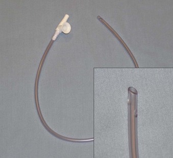
Numerous commercial suction catheters exist.5,7,29 The ideal catheter is one that optimizes secretion removal and minimizes tissue trauma. Specific features of the catheters include the material of construction, frictional resistance, size (length and diameter), shape, and position of the aspirating holes. An opening at the proximal end of the catheter to allow the entrance of room air, neutralizing the vacuum without disconnecting the vacuum apparatus, is ideal. The proximal hole should be larger than the catheter lumen. Tracheal suctioning can occur only with occlusion of this proximal opening. The conventional suction catheter has side holes and end holes (Fig. 14-6).
4 Complications
Complications of suctioning can be significant.7,30 Although the suction vacuum is used to remove secretions, it also removes O2-enriched gases from the airway. If inappropriately applied and monitored, suctioning can produce significant hypoxemia. The use of arterial O2 monitors (e.g., pulse oximetry) can often help detect alterations in SaO2, heart rate, and the presence of dysrhythmias.
Cardiovascular alterations are common. Dysrhythmias and hypotension are the most frequent cardiac complications. Arterial hypoxemia (and eventually myocardial hypoxia) and vagal stimulation from tracheal suctioning are recognized precipitory causes of cardiovascular complications. Coughing induced by stimulation of the airway can reduce venous return and ventricular preload. Avoidance of hypoxemia, prolonged suctioning (>10 seconds), and appropriate monitoring and sedation help reduce the incidence and significance of these complications.31
B Chest Physical Therapy
1 Postural Drainage and Positional Changes
The fundamental goal of postural drainage is to move loosened secretions toward the proximal airway for eventual removal. Pulmonary drainage takes advantage of the normal pulmonary anatomy and gravitational flow. Flow of secretions is optimized by liquefaction (see “Humidifiers”).
The primary indications for pulmonary drainage are malfunctioning of normal bronchial hygiene mechanisms and excessive or retained secretions.7,9,32,33 In patients with ineffective lung volumes and cough, pulmonary drainage can be used prophylactically to prevent accumulation of secretions. Clinical conditions that typically benefit from pulmonary drainage include bronchiectasis, cystic fibrosis (CF), COPD, asthma, lung abscess, spinal cord injuries, atelectasis, pneumonia, and healing after thoracic and abdominal surgery.
To administer postural drainage appropriately, the practitioner must be able to understand the location of the involved lung segments and the proper position to optimize drainage into the proximal airway. The lungs are divided into lobes, segments, and subsegments, and fluid drainage is directed centrally to the hilum (Table 14-7).
| Right Side | Left Side |
|---|---|
| Upper Lobe | Upper Lobe |
| Apical | Apical-posterior |
| Posterior | Anterior |
| Anterior | |
| Middle Lobe | Lingula |
| Lateral | Superior |
| Medial | Inferior |
| Lower Lobe | Lower Lobe |
| Superior | Superior |
| Medial basal | Anteromedial basal |
| Anterior basal | Lateral basal |
| Lateral basal | Posterior basal |
| Posterior basal |
Precise anatomic descriptions of the various pulmonary subsegments and positions are beyond the scope of this chapter. The large posterior and superior basal segments of the lower lobe are commonly involved in hospital patients with atelectasis and pneumonia. In the typical hospital patient, these segments are most gravity dependent, causing stasis of secretions (Fig. 14-7).
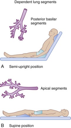
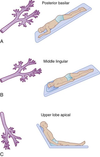
Appropriate positioning of the patient can enhance gravitational flow. This therapy also includes turning or rotating the body around its longitudinal axis. Newer critical care beds have this feature incorporated into their design and function. Commonly employed positions for postural drainage are demonstrated in Figure 14-8.
Postural drainage can produce physiologic and anatomic stresses that are potentially detrimental to specific patients.34 Alterations in the cardiovascular system from abrupt changes in position are well recognized. Hypotension, dysrhythmias, or congestive heart failure that is due to changes in preload can be induced by positional change.  relationships are altered by changes in position. When pulmonary drainage occurs in the uppermost position, blood preferentially flows to the gravity-dependent, nondiseased segments, improving the ventilation-perfusion relationships. The head-down position, which is commonly used, is best avoided in patients with intracranial disease. Decreased venous return from the head can increase intracranial pressure.
The prone position has been demonstrated to improve oxygenation in patients with acute respiratory distress syndrome. The placement of critically ill patients in the prone position can be done without significant morbidity despite the presence of multiple sites of vascular access and intubation. The improvement in oxygenation probably depends on recruitment of collapsed alveoli, more evenly distributed pleural pressure gradients, and caudad movement of the diaphragm.35
Continuous rotational therapy employs dedicated intensive care unit beds that slowly and continuously rotate the patient along a longitudinal axis. The theory is that rotation of patients prevents gravity-dependent airway closure or collapse, worsening of pulmonary compliance and atelectasis, and pooling of secretions and subsequent pulmonary infection caused by long-term immobilization.36 The use of rotational therapy may lead to a significantly lower incidence of patients diagnosed with pneumonia compared with patients cared for on conventional beds.37
2 Percussion and Vibration Therapy
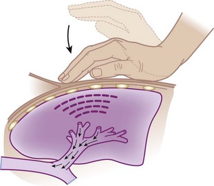
Percussion and vibration therapy are used in conjunction with postural drainage to loosen and mobilize secretions that are adherent to the bronchial walls.7,38 Percussion involves a manually produced, rhythmic vibration of varying intensity and frequency. In a clapping motion (cupped hands), a blow is delivered during inspiration and expiration over the affected area while the patient is in the appropriate position for postural drainage (Fig. 14-9).
Vibration therapy is used to promote bronchial hygiene in a fashion similar to chest percussion. Manually or mechanically (Fig. 14-10) gentle vibrations are transmitted through the chest wall to the affected area during exhalation. Vibration frequencies in excess of 200/min can be achieved if the procedure is done correctly. In patients receiving IPPB, all chest physical therapy procedures should be performed during the IPPB.
3 Incentive Spirometry
In the 1970s, alternative methods for prophylactic bronchial hygiene were developed to replace the more costly and controversial use of IPPB. Incentive spirometry (IS) was developed after several techniques using expiratory maneuvers (e.g., blow and glove bottles) and CO2-induced hyperventilation were found to be clinically ineffective or to cause other risks.5,7,9
The physiologic principle of SMI is to produce a maximal transpulmonary pressure gradient by generating a more negative intrapleural pressure. This pressure gradient produces alveolar hyperinflation with maximal airflow during the inspiratory phase.39
Various clinical models of incentive spirometers are available.9 The devices vary in how they function, guide the therapy, or recognize the achievements. Each manufacturer provides instructions for use that should be followed. The devices are aimed at generating the largest inspiratory volumes during 5 to 15 seconds. The actual device used or rate of flow is not as important as the frequency of use and the attainment of maximal inspiratory volumes and sustained inspiration. Maximal benefit with most devices can be achieved only with user education.
Although the use of IS is widespread throughout the United States, many reviews cast doubts on the superiority of IS in reducing postoperative pulmonary complications over other methods of postoperative respiratory care.40 Meta-analyses suggest that IS does not prevent pulmonary complications in patients undergoing coronary artery bypass grafting (CABG) or upper abdominal surgery.41–43
C Intermittent Positive-Pressure Breathing
In the past 40 years, few respiratory care therapies have been as controversial as IPPB.5,7,9 Objective data assessing therapeutic benefit relative to cost and alternative therapies have been less than confirmatory.44,45 Numerous conferences have been sponsored by medical organizations to evaluate literature supporting and opposing IPPB. The inconclusive result of these efforts has significantly reduced the use of IPPB in contemporary clinical practice. IPPB has been largely replaced with other forms of noninvasive positive-pressure ventilation (PPV), such as CPAP and bi-level positive airway pressure (BiPAP). This section is intended to define IPPB, discuss its indications, and describe the technique of administration and potential side effects and complications. An extensive historical and in-depth analysis of IPPB controversies is beyond the scope of this section.
1 Indications
IPPB is the therapeutic application of inspiratory positive pressure to the airway and is distinctly different from intermittent PPV or other means of prolonged, continuous ventilation. The clinical indications for IPPB have evolved over the lifetime of this therapy and include the need to provide a large VT with resultant lung expansion, provide for short-term ventilatory support (although this has been replaced with noninvasive PPV), and administer aerosol therapy.46 The fundamental basis and primary goal of IPPB is to provide a larger VT to the spontaneously breathing patient in a physiologically tolerable manner. If this goal is achieved, IPPB could be employed to improve and promote the cough mechanism, to improve distribution of ventilation, and to enhance delivery of inhaled medications.
2 Administration
The effectiveness of IPPB depends on the individual administering the therapy.9 It is incumbent for that individual to understand the appropriate operation, maintenance, and clinical application of the mechanical device employed; to select the appropriate patient; to provide the necessary education to the patient to optimize the effort; to assess the effectiveness relative to goals and indications; and to identify complications or side effects associated with the therapy.
The physiologic side effects and complications associated with IPPB are well described in the literature.9 Hyperventilation and variable oxygenation can result from IPPB therapy. Hypocarbia (resulting in a respiratory alkalosis) due to an increased VT and respiratory frequency can produce altered electrolyte concentrations (e.g., K+), dizziness, muscle tremors, and tingling and numbness of the extremities. Proper instruction to the patient and a 5 to 10 minute rest period after therapy can minimize this problem. Hypoxemia and hyperoxia caused by inaccurately delivered FIO2 can be a concern in patients with severe COPD.
There are few definite contraindications to IPPB.47 Relative contraindications to IPPB are focused on its lack of documented efficacy. Untreated pneumothorax is a definite contraindication to IPPB. Relative contraindications include elevated intracranial pressures (>15 mm Hg), hemodynamic instability, esophageal and gastric conditions such as recent surgery or fistulas, and recent intracranial surgery. Good clinical contraindications are lack of a definite indication for IPPB or an available, less expensive alternative therapy.
D Noninvasive Ventilation
1 Indications
Perioperative NIV use can be viewed as prophylactic or therapeutic.48 Prophylactic use of NIV involves administration of NIV after extubation to patients at risk for respiratory distress (e.g., cardiac, thoracic, or abdominal surgery, obstructive sleep apnea, COPD, congestive heart failure). Data continue to emerge regarding the potential beneficial use of perioperative CPAP in reducing postoperative pulmonary complications in patients undergoing cardiothoracic and abdominal surgery.49,50 The therapeutic use of NIV in the perioperative setting may aid in reducing symptoms of respiratory distress, hypoxemia, or hypoventilation. Further studies need to validate NIV for prophylactic and therapeutic use in a broader patient population.
IV Inhalation Therapy
The advantages of delivering drugs by inhalation include the following: easier access, rapid onset of action, reduced extrapulmonary side effects, reduced dosage, coincidental application with aerosol therapy for humidification, and general psychological support with treatment.5,7,9 In the nonintubated patient, aerosol therapy necessitates the patient’s cooperation and skilled help. The equipment is a potential source of nosocomial infections.19 Aerosol therapy has many of the same disadvantages as humidification. Although drug use is often reduced, precise titration and dosages are difficult to ascertain because of variable degrees of drug deposition in the airway.
The following sections provide an overview of inhalation pharmacology and discuss the basic principles, devices for medication delivery, and specific pharmacologic agents that are employed. A more comprehensive topic review and specific drug information are available in reference texts.48–50
B Aerosolized Drug Delivery Systems
Therapeutic aerosols are commonly employed in respiratory care. Inhalation delivery of drugs can often produce therapeutic drug effects with reduced toxicity. The effectiveness of aerosols is related to the amount of drug delivered to the lungs. The pulmonary deposition of aerosolized drugs is a result of drug sedimentation that is due to gravity, inertial impact that is due to airway size, and directional change of airflow and kinetic energy.7 Aerosol delivery also depends on particle size, pattern of inhalation, and degree of airway obstruction. Particle size should be smaller than 5 µm; otherwise, the particles may become trapped in the upper airway rather than following airflow into the lungs. Aerosol particles that can traverse artificial airways (e.g., ETT) are usually less than 2 µm in diameter. Particles less than 2 µm are deposited in peripheral airways. Particles less than 0.6 µm in diameter are often exhaled before reaching their site of action.
DPIs and pressurized MDIs are the most common delivery systems because of their low cost and ease of use. The MDI is a convenient, self-contained, and commonly employed method of aerosolized drug delivery (Figs. 14-11 and 14-12).5,9 These prefilled drug canisters are activated by manual compression and deliver a predetermined unit (metered) of medication. Appropriate instruction is necessary for optimal use.51 With the canister in the upside-down position, the device should be compressed only once per inhalation. A slow maximal inspiration with a breath-hold is typically recommended. It is imperative that the tongue not obstruct flow, but it is controversial whether the device should be placed in the mouth or held several centimeters from the lips with the mouth wide open. Concerns about excessive oral deposition of large particles must be offset against consistency of administration when the device is held away from the mouth. Other issues regarding use of MDIs include ideal lung volume for actuation, time of inspiratory hold, and inspiratory flow rate. If multiple doses are prescribed, an interval of several minutes between puffs is advisable. Most pharmaceutical manufacturers recommend 1 to 2 minutes between doses. However, studies have not shown any consistent difference in pulmonary function in extending the time interval between doses.52,53
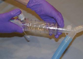
Figure 14-11 Metered-dose inhaler and circuit inspiratory limb spacer (Aero Vent).
(Courtesy of Monaghan Medical, Plattsburgh, NY.)
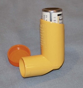
MDI drug delivery is associated with several problems. Manual coordination is necessary to activate the canister. Arthritis can cause difficulty, as can misaiming the aerosol. Pharyngeal deposition can lead to local abnormalities (e.g., oral candidiasis from aerosolized corticosteroids). Systemic effects that are caused by swallowing the drug can be reduced if the pharynx is rinsed after inhalation to reduce pharyngeal deposition.5 Newer MDI devices have been designed to reduce some of these problems. Several spacing devices are available as extensions to MDIs. Spacers are designed to eliminate the need for hand-breath coordination and reduction of large-particle deposition in the upper airway.
The gas-powered nebulizers can be handheld or placed in line with the ventilatory circuit (Fig. 14-13).5,9 The handheld devices are typically employed for more acutely ill individuals and as an alternative to an MDI. The full handheld system uses a nebulizer, a pressurized gas source, and a mouthpiece or face mask. Patients’ cooperation is not required, and high doses of drugs can be delivered. Disadvantages include expense and decreased portability.
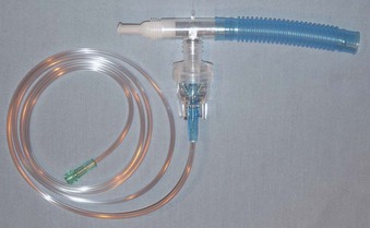
The total volume to be nebulized is usually 3 mL (see “Pharmacologic Agents”) at gas flows of 6 to 8 L/min (flow is device dependent). The treatment time is usually 5 to 10 minutes. During the course of treatment, the patient’s vital signs and subjective tolerance must be monitored. Aerosolization of medication for drug delivery is different from aerosol therapy for humidification (see “Humidifiers”).
The MDI and the gas-powered nebulizers can be used in line with an artificial airway or ventilator circuit, or both (see Figs. 14-11 and 14-13) The drug delivery system is positioned in the inspiratory limb and as proximal to the artificial airway as possible. With this configuration, drug delivery is equivalent between MDI and nebulizer.54 In-line drug delivery is usually less efficient in ventilated patients than in spontaneously breathing, nonintubated patients because of the breathing pattern, drug deposition on the ETT, and airway disease.55
C Pharmacologic Agents
1 Mucokinetic Drugs
Mucokinetic drugs are employed to enhance mucociliary clearance. These agents can be classified according to their mechanism of action. Hypoviscosity agents are the most commonly employed mucokinetic agents. Saline, sodium bicarbonate, and alcohol have been used to affect mucus viscosity by disrupting the mucopolysaccharide chains that are the primary components of mucus. The other category of mucokinetic aerosol agents is made up of the mucolytics. The following sections offer a synopsis of the various drugs in these two groups.56
a Hypoviscosity Agents
Alcohol (ethyl alcohol and ethanol) decreases the surface tension of pulmonary fluid. The typical concentration is 30%, and the dosage is 4 to 10 mL.57 The primary indication is pulmonary edema. This agent should be administered by side-arm nebulization or IPPB but not as a heated aerosol. The contraindication is a hypersensitivity to alcohol or its derivative. Side effects include airway irritation, bronchospasm, and local dehydration.
b Mucolytic Agents
Acetylcysteine 10% (Mucomyst) is an effective mucolytic. The mechanism of action is lysis of the disulfide bonds in mucopolysaccharide chains, reducing the viscosity of the mucus. The indication is for management of viscous, inspissated, mucopurulent secretions. The actual effectiveness in the treatment of mucostasis is inconclusive, and each individual must be monitored to determine the benefit of therapy. The usual dosage is 2 to 5 mL every 6 hours.54 Hypersensitivity is a contraindication. In general, acetylcysteine is relatively nontoxic. Side effects include unpleasant taste and odor, local irritation, inhibition of ciliary activity, and bronchospasm. For these reasons, pretreatment with a bronchodilator is recommended. Other reported side effects include nausea and vomiting, stomatitis, rhinorrhea, and generalized urticaria. Acetylcysteine is incompatible with several antibodies. The drug should be avoided or used with extreme caution in patients with bronchospastic airway disease. Other special concerns are a need for refrigeration, reactivity with rubber, and its limited use after opening (96 hours).58
Mesna (mistabron) is a thiol-containing compound that can lyse the disulfide bonds on mucoproteins, and it has been shown to support thinning of secretions.59 In addition to the direct mucolytic activity, Mesna is a hypertonic solution and may reduce viscosity of secretions by a second mechanism. As for acetylcysteine, studies of Mesna have been unable to demonstrate conclusive benefit of secretion clearance or improvement in lung compliance despite concomitant bronchodilator adminstration.59 When given by nebulizer, 1 mL of Mesna is combined with a bronchodilator, such as albuterol or salbutamol. It can also be administered as a bolus of 600 mg (3 mL) through the ETT. It usually is well tolerated, with bronchospasm and hypersensitivity as possible side effects.
Recombinant human DNase (rhDNase) promotes lysis of DNA that is present in the secretions of patients with CF or infected secretions. The abundance of DNA increases the viscosity of these secretions. A few reports and retrospective analyses have shown rhDNase to improve secretion clearance and atelectasis.60 The increased cost of rhDNAse limits its widespread use in clinical practice.
2 Bronchodilators and Antiasthmatic Drugs
Acute and chronic bronchospastic airway diseases afflict many individuals. Many drugs that vary primarily by their mechanism of action and route of delivery are available to manage this problem. The following sections deal only with aerosolized drugs that are commonly employed in the therapy of bronchospastic airway disease (Table 14-8).16,61,62 The drugs are grouped by their mechanism of action: sympathomimetics, anticholinergics, corticosteroids, and cromolyn. A comprehensive review of these drugs, the various mechanisms for bronchodilation, and the management of specific pathophysiologic problems is beyond the scope of this chapter.
TABLE 14-8 Aerosolized Bronchodilators and Antiasthmatic Drugs
| Type of Drug (Mechanism) | Method | Dose* |
|---|---|---|
| Sympathomimetics | ||
| (β2-Agonists; increase in cyclic AMP) | ||
| Short-Acting Beta Agonists | ||
| Albuterol (Ventolin, Proventil) | MDI/Neb | 2 puffs (90 µg/puff) q4hr prn |
| Levalbuterol hydrochloride (Xopenex) | Neb | 0.63–1.25 mg nebulized solution q6–8hr |
| Pirbuterol acetate (Maxair) | MDI | 2 puffs (200 µg/puff) q4hr prn |
| Racemic epinephrine | Neb | 0.25 mL in 3.5 mL |
| Long-Acting Beta Agonists | ||
| Salmeterol xinafoate (Serevent) | DPI | 1 puff (50 µg) bid |
| Formoterol fumarate (Foradil) | DPI | 1 capsule (12 µg) by Aerolizer inhaler bid |
| Anticholinergics | ||
| (Cholinergic blockers; increase β stimulation) | ||
| Ipratropium bromide (Atrovent) | MDI/Neb | 2 puffs (17 µg/puff) qid 17 µg (0.02%) qid |
| Tiotropium bromide (Spiriva) | DPI | 1 capsule inhaled (18 µg) by HandiHaler qd |
| Anti-Inflammatories | ||
| Inhaled Corticosteroids (Anti-inflammatory; inhibit leukocyte migration; potentiate β agonists) |
||
| Beclomethasone acetate (Vanceril, Beclovent) | MDI | 1–4 puffs (40 µg/puff) bid |
| Flunisolide (AeroBid) | MDI | 2–4 puffs (250 µg/puff) bid |
| Triamcinolone acetonide (Azmacort) | MDI | 2–8 puffs (100 µg/puff) bid |
| Budesonide (Pulmicort) | DPI/Neb | 1–4 puffs (200 µg/puff) bid 0.25 mg/2 mL bid 0.5 mg/2 mL bid |
| Fluticasone propionate (Flovent) | MDI | 44, 110, or 220 µg; up to a maximum of 880 µg/day |
| Mometasone furoate (Asmanex) | DPI | 1–2 puffs (220 µg/puff) qd |
| Combination Products | ||
| Albuterol sulfate/ipratropium bromide (Combivent) | MDI/Neb | 2 puffs (0.09 mg/0.018 mg/puff) qid 1 vial (3 mg/0.5 mg) qid |
| Fluticasone propionate/salmeterol Xinafoate (Advair) |
DPI | 100, 250, or 500 µg/50 µg; 1 puff bid |
AMP, Adenosine monophosphate; bid, twice per day; DPI, dry-powder inhaler; MDI, metered-dose inhaler; Neb, nebulizer; qd, once per day; qid, four times per day.
* Dosages may vary; references to specific drug inserts are recommended.
a Sympathomimetics
Sympathomimetics include the β-adrenergic agonists and methylxanthines (not available in aerosol). The rhDNase-adrenergic agents couple to the β2-adrenoreceptor through the G protein α subunit to adenylate cyclase, which results in an increase in intracellular cyclic adenosine monophosphate (cAMP), which leads to activation of protein kinase A. Activated protein kinase A inhibits phosphorylation of certain muscle proteins that regulate smooth muscle tone and inhibits release of calcium ion from intracellular stores. Responses of sympathomimetic drugs usually are classified according to whether the effects are α, β1, or β2. The β2 receptors are responsible for bronchial smooth muscle relaxation. The common side effects associated with β-adrenergic agonists result from their additional β1 and α effects. The β1 effects cause an increase in heart rate, dysrhythmias, and cardiac contractility; α effects increase vascular tone. Potent β2 stimulants can produce unwanted symptoms: anxiety, headache, nausea, tremors, and sleeplessness. Prolonged use can lead to receptor downregulation and reduced drug response. Ideally, the more pure the β2 response, the better the therapeutic benefit relative to side effects. The following sympathomimetics are commonly employed in clinical practice.5,7,39,58
Racemic epinephrine 2.25% (Vaponephrine) is a mixture of levo and dextro isomers of epinephrine. It is a weak β and mild α drug. The α effects provide mucosal constriction. In the aerosol form, this drug acts as a good mucosal decongestant. The drug has minimal bronchodilator action. Cardiovascular side effects are limited. Typical dosage is 0.5 mL (2.25%) in 3.5 mL of saline, given as frequently as every hour in adult patients. Racemic epinephrine is commonly mixed with 0.25 mL (1 mg) of dexamethasone or budesonide for the management of post-extubation swelling and croup (see “Antiallergy and Asthmatic Agents”).
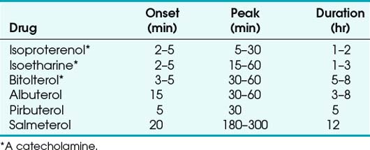
Newer inhaled β-adrenergic drugs include salmeterol, pirbuterol, and bitolterol (a catecholamine). Salmeterol can be administered as an oral inhalation powder twice a day 50 µg. Pirbuterol acetate is usually administered through a pressurized MDI (200 µg). Bitolterol can be provided as a pressurized MDI or a solution. Salmeterol was the first long-acting adrenergic bronchodilator approved for use in the United States. Its duration of action is about 12 hours, with an onset of about 20 minutes and a peak effect occurring in 3 to 5 hours. It is particularly useful in patients with nocturnal asthma because of its longer duration of action. The prolonged effect of some of the newer bronchodilators results from their increased lipophilicity (Table 14-9).
b Anticholinergic Agents and Antibiotics
Ipratropium bromide (Atrovent) is a commonly used anticholinergic. Its effects are primarily on the muscarinic receptors of bronchial smooth muscle. It is available as an MDI. The standard dosage is 34 µg taken four times per day (17 µg/puff). Hypersensitivity to the drug is a contraindication. Caution should be exercised in patients with narrow-angle glaucoma. Tiotropium is a long-acting anticholinergic agent that has shown to improve lung function and reduce exacerbations of COPD with once-daily dosing.63 The dosage is 2 puffs of an 18-µg capsule taken once daily using the supplied DPI. The side effects are similar to ipratropium bromide, with most common symptoms being dry mouth and upper respiratory tract infections. Rarely, inhaled anticholinergic drugs have been associated with paradoxical bronchospasm.
Antibiotics are also delivered by an inhalational route. Aerosolized tobramycin is used in patients with CF, and ribavirin is employed in children against respiratory syncytial virus. Pentamidine can be employed as prophylaxis against Pneumocystis (carinii) jiroveci. However, the support for the general use of nebulized antibiotics in ventilator-associated pneumonia (VAP) is inconclusive. As a result, the addition of nebulized antibiotics is reserved for multidrug-resistant organism pneumonia refractory to first-line therapy. The use of aerosolized gentamycin or vancomycin, in addition to systemic antibiotics, for treatment of tracheobronchitis led to quicker resolution of pneumonia, decreased bacterial resistance, and less recurrence of VAP.64 Nebulized polymyxins (e.g., colistin) allow focused delivery of antibiotics that were historically underutilized because of significant nephrotoxicity with systemic administration. The evidence for the use of nebulized colistin is promising but remains inconclusive. When added to a regimen of systemic antibiotics in patient with multidrug-resistant gram-negative bacteria, nebulized colistin has shown to be beneficial for treatment of pneumonia without systemic side effects.65
c Antiallergy and Asthmatic Agents
Newer mediator antagonists include zafirlukast, montelukast, and zileuton. Zafirlukast and montelukast work as leukotriene receptor antagonists and selectively inhibit leukotriene receptors LTD4 and LTE4. Leukotrienes are produced by 5-lipoxygenase from arachidonic acid and stimulate leukotriene receptors to cause bronchoconstriction and chemotaxis of inflammatory cells. As with cromolyn sodium, these agents should not be used for acute asthmatic attacks but rather for long-term prevention of bronchoconstriction.62
Corticosteroids are commonly used for maintenance therapy in patients with chronic asthma.66,67 The mechanism of action is attributed to their anti-inflammatory properties, reducing leakage of fluids, inhibiting migration of macrophages and leukocytes, and possibly blocking the response to various mediators of inflammation. Corticosteroids have been reported to potentiate the effects of the sympathomimetic drugs.9 Systemic and topical side effects can occur with inhaled corticosteroids. These effects include adrenal insufficiency, acute asthma episodes, possible growth retardation, and osteoporosis. Local effects include oropharyngeal fungal infections and dysphonia. Adrenal suppression is usually not a concern with doses below 800 µg/day.
VI Clinical Pearls
• Hypoxemia may be defined as a deficiency of O2 tension in the arterial blood, typically defined as a PaO2 less than 80 mm Hg. The most common perioperative cause of hypoxemia is capillary shunt (atelectasis).
• A low-flow, variable-performance system depends on room air entrainment to meet the patient’s peak inspiratory and minute ventilatory demands that are not met by the inspiratory gas flow or O2 reservoir alone.
• High-flow, fixed-performance systems are nonrebreathing systems that provide the entire inspiratory atmosphere needed to meet the peak inspiratory flow and minute ventilatory demands of the patient. To meet the patient’s peak inspiratory flow, the flow rate and reservoir are very important. Flows of 30 to 40 L/min (or four times the measured minute volume) are often necessary.
• O2 therapy must be used appropriately in patients with severe chronic obstructive pulmonary disease (COPD) due to a risk of developing respiratory distress. Disturbances in ventilation and perfusion develop in patients with COPD, and through hypoxic pulmonary vasoconstriction, the perfusion is redistributed to areas of higher O2 tension. Increasing mixed venous or alveolar O2 tension can reverse this shunting and worsen  matching.
• O2 toxicity becomes clinically important after 8 to 12 hours of exposure to a high FIO2 level. O2 toxicity may result from direct exposure of the alveoli to a high FIO2 level. Healthy lungs appear to tolerate FIO2 levels of less than 0.6. In damaged lungs, FIO2 levels greater than 0.50 may result in a toxic alveolar O2 concentration.
• Airway suctioning is commonly employed in respiratory care to promote optimal tracheobronchial toilet and airway patency in critically ill patients. Because of the perceived simplicity and limited complications, airway suctioning is frequently employed.
• Percussion and vibration therapy are used in conjunction with postural drainage to loosen and mobilize secretions that are adherent to the bronchial walls.17,48 Percussion involves a manually produced, rhythmic vibration of varying intensity and frequency.
• Normal, spontaneous breathing patterns have periodic hyperinflations that prevent the alveolar collapse associated with shallow tidal ventilation breathing patterns. Narcotics, sedative drugs, general anesthesia, cerebral trauma, immobilization, and abdominal or thoracic surgery can promote shallow tidal ventilation breathing patterns. Incentive spirometry (IS) is commonly employed in the postoperative period to encourage patients to generate a maximal tidal volume breath. However, IS has yet to be proved to reduce postoperative pulmonary complications.
• Perioperative noninvasive ventilation (NIV) is both a prophylactic and therapeutic modality. Prophylactic use of NIV has emerged as a measure to reduce postoperative pulmonary complications in patients undergoing cardiothoracic and abdominal. Therapeutic use of NIV in the perioperative setting may aid in reducing symptoms of respiratory distress, hypoxemia, or hypoventilation.
• The metered-dose inhaler (MDI) and the gas-powered nebulizers may be used with an artificial airway or ventilator circuit, or both. The drug delivery system is positioned in the inspiratory limb as proximal to the artificial airway as possible. This position makes drug delivery equivalent between MDI and nebulizer.
All references can be found online at expertconsult.com.
5 Kacmarek RM, Stoller JK. Current respiratory care. Toronto: BC Decker, 1988.
7 Shapiro BA, Kacmarek RM, Cane RD, et al. Clinical application of respiratory care, ed 4. St Louis: Mosby; 1991.
48 Jaber S, Chanques G, Jung B. Postoperative noninvasive ventilation. Anesthesthesiology. 2010;112:453–461.
54 Dolovich MB, Ahrens RC, Hess DR, et al. Device selection and outcomes of aerosol therapy: Evidence-based guidelines: American College of Chest Physicians/American College of Asthma, Allergy, and immunology. Chest. 2005;127:335–371.
1 Belda FJ, Aguilera L, de la Asuncion JG, et al. Supplemental perioperative oxygen and the risk of surgical wound infection: A randomized controlled trial. JAMA. 2005;294:2035–2042.
2 Greif R, Akca O, Horn E, et al. Supplemental perioperative oxygen to reduce the incidence of surgical-wound infection. N Engl J Med. 2000;342:161–167.
3 Qadan M, Akca O, Mahid SS, et al. Perioperative supplemental oxygen therapy and surgical site infection. Arch Surg. 2009;144:359–366.
4 Maragakis LL, Cosgrove SE, Martinez EA, et al. Intraoperative fraction of inspired oxygen is a modifiable risk factor for surgical site infection after spinal surgery. Anesthesthesiology. 2009;110:556–562.
5 Kacmarek RM, Stoller JK. Current respiratory care. Toronto: BC Decker, 1988.
6 Marini JJ. Postoperative atelectasis: Pathophysiology, clinical importance, and principles of management. Respir Care. 1984;29:516.
7 Shapiro BA, Kacmarek RM, Cane RD, et al. Clinical application of respiratory care, 4th ed. St Louis: Mosby; 1991.
8 Gibson RL, Comer PB, Beckham RW, et al. Actual tracheal oxygen concentrations with commonly used oxygen equipment. Anesthesiology. 1976;44:71–73.
9 Burton GL, Hodgkin JE. Respiratory care, 2nd ed, Philadelphia: JB Lippincott, 1984.
10 Scacci R. Air entrainment masks: Jet mixing is how they work; The Bernoulli and Venturi principles are how they don’t. Respir Care. 1979;24:928.
11 Gommersall CD, Joynt GM, Freebairn RC, et al. Oxygen therapy for hypercapneic patients with chronic obstructive pulmonary disease and acute respiratory failure: A randomized, controlled pilot study. Critical Care Med. 2002;30:113–116.
12 Robinson TD, Freiberg DB, Regnis JA, Young IH. The role of hypoventilation and ventilation-perfusion redistribution in oxygen-induced hypercapnia during acute exacerbations of chronic obstructive pulmonary disease. Am J Respir Crit Care Med. 2000;161:1524–1529.
13 Wettstein RB, Shelledy DC, Peters JI. Delivered oxygen concentrations using low-flow and high-flow nasal cannulas. Respir Care. 2005;50:604–609.
14 Waugh JB, Granger WM. An evaluation of 2 new devices for nasal high-flow gas therapy. Respir Care. 2004;49:902–906.
15 Tobin A. High-flow nasal oxygen generates positive airway pressure in adult volunteers. Aust Crit Care. 2007;20:126–131.
16 Kacmarek RM. Humidity and aerosol therapy. In: Pierson DJ, Kacmarek RM. Foundations of respiratory care. New York: Churchill Livingstone; 1992:793–824.
17 Hall TO. Aerosol generators and humidifiers. In: Barnes TA, ed. Respiratory care practice. Chicago: Year Book; 1988:356–405.
18 Klein EF, Shah DA, Shah NJ, et al. Performance characteristics of conventional and prototype humidifiers and nebulizers. Chest. 1973;64:690–696.
19 Craven DE, Goulartet A, Maki BJ. Contaminated condensate in mechanical ventilator circuits: A risk factor for nosocomial pneumonia? Am Rev Respir Dis. 1984;129:625–628.
20 Barnes TA, Watson ME. Oxygen delivery performance of four adult resuscitation bags. Respir Care. 1982;27:139–146.
21 Barnes TA, Watson ME. Oxygen delivery performance of old and new designs of the Laerdal, Vitalograph and AMBU adult manual resuscitators. Respir Care. 1983;28:1121–1128.
22 Carden E, Friedman D. Further studies of manually operated self-inflating resuscitation bag. Anesth Analg. 1977;56:202–206.
23 Crossley DJ, McGuire GP, Barrow PM, et al. Influence of inspired oxygen concentration on deadspace, respiratory drive, and PaCO2 in intubated patients with chronic obstructive pulmonary disease. Crit Care Med. 1997;25:1522–1523.
24 Aubier M, Murciano D, Fournier M, et al. Central respiratory drive in acute respiratory failure of patients with chronic obstructive pulmonary disease. Am Rev Respir Dis. 1980;122:191–199.
25 Hanson CW, III., Marshall BE, Frasch HF, Marshall C. Causes of hypercarbia in patients with chronic obstructive pulmonary disease. Crit Care Med. 1996;24:23–28.
26 Clark JM, Lambertsen CJ, Gelfand R, et al. Effects of prolonged oxygen exposure at 1.5, 2.0, or 2.5 ATA on pulmonary function in men (predictive studies V). J Appl Physiol. 1999;86:243–259.
27 Deneke SM, Fanburg BL. Normobaric oxygen toxicity of the lung. N Engl J Med. 1980;303:76–86.
28 Weibel ER. Oxygen effect on lung cells. Arch Intern Med. 1971;128:54–56.
29 Chapman GA, Kim CS, Frankel J, et al. Evaluation of the safety and efficiency of new suction catheter design. Respir Care. 1986;31:889.
30 Demers RR. Complications of endotracheal suctioning procedures. Respir Care. 1982;27:453.
31 Cohen D, Horiuchi K, Kemper M, et al. Modulating effects of propofol on metabolic and cardiopulmonary responses to stressful intensive care procedures. Crit Care Med. 1996;24:612–617.
32 Harris JA, Jerry BA. Indications and procedures for segmental bronchial drainage. Respir Care. 1975;20:1164.
33 Zadai CL. Physical therapy for the acutely ill medical patient. Phys Ther. 1981;61:1746.
34 Tyler ML. Complications of positioning and chest physiotherapy. Respir Care. 1982;27:458.
35 Jolliett P, Bulpa P, Chevrolet RC. Effects of prone position on gas exchange and hemodynamics in severe respiratory distress syndrome. Crit Care Med. 1998;12:1977–1985.
36 Stiller K. Physiotherapy in intensive care: Towards an evidence-based practice. Chest. 2000;118:1801–1813.
37 deBoisblanc BP, Castro M, Everret B, et al. Effect of air-supported, continuous, postural oscillation on the risk of early ICU pneumonia in nontraumatic critical illness. Chest. 1993;103:1543–1547.
38 Radford R. Rational basis for percussion: Augmented mucociliary clearance. Respir Care. 1982;27:556.
39 Ziment I. Why are they saying bad things about IPPB? Respir Care. 1973;18:677.
40 Overend TJ, Anderson CM, Lucy SD, et al. The effect of incentive spirometry on postoperative pulmonary complications: A systematic review. Chest. 2001;120:971–978.
41 Cattano D, Altamirano A, Vannucci A, et al. Preoperative use of incentive spirometry does not affect postoperative lung function in bariatric surgery. Transl Res. 2010;156:265–272.
42 Freitas ERFS, Soares B, Cardoso JR, et al. incentive spirometry for preventing pulmonary complications after coronary bypass graft. Cochrane Database Syst Rev. 3, 2007. CD004466
43 Guimarães MMF, El Dib RP, Smith AF, Matos D. Incentive spirometry for prevention of postoperative pulmonary complications in upper abdominal surgery. Cochrane Database Syst Rev. 3, 2009. CD006058
44 Curtis JK, Liska AP, Rasmussen HK, et al. IPPB therapy in chronic obstructive pulmonary disease. JAMA. 1968;206:1037.
45 Laffont I, Bensmail D, Lortat-Jacob S, et al. Intermittent positive-pressure breathing effects in patients with high spinal cord injury. Arch Phys Med Rehabil. 2008;89:1575–1579.
46 American Association for Respiratory Care. AARC clinical practice guideline: Intermittent positive pressure breathing—2003 Revision and update. Respir Care. 2003;48:540–546.
47 Scanlan CL, Wilkins RL, Stoller JK. Egan’s fundamentals of respiratory care, 7th ed. St Louis: Mosby; 1999.
48 Jaber S, Chanques G, Jung B. Postoperative noninvasive ventilation. Anesthesiology. 2010;112:453–461.
49 Ferreyra GP, Baussano I, Squadrone V, et al. Continuous positive airway pressure for treatment of respiratory complications after abdominal surgery: A systematic review and meta-analysis. Ann Surg. 2008;247:617–626.
50 Zarbock A, Mueller E, Netzer S, et al. Prophylactic nasal continuous positive pressure airway pressure following cardiac surgery protects from postoperative pulmonary complications: A prospective, randomized, controlled trial in 500 patients. Chest. 2009;135:1252–1259.
51 Self TH, Brooks JB. Necessity of teaching patients correct bronchodilator inhalation technique. Immunol Allergy Pract. 1982;4:40.
52 Lawford P, McKenzie D. Pressurized aerosol inhaler technique: How important are inhalation from residual volume, inspiratory flow rate and the time interval between puffs? Br J Dis Chest. 1983;77:276–281.
53 Lindbladh C, Smith P, Jackson L, et al. A comparison of the bronchodilator effect of salbutamol inhaled via Turbuhaler as two consecutive doses or as two divided doses at different time intervals. Int J Pharm. 1999;190:57–62.
54 Dolovich MB, Ahrens RC, Hess DR, et al. Device selection and outcomes of aerosol therapy: Evidence-based guidelines: American College of Chest Physicians/American College of Asthma, Allergy, and Immunology. Chest. 2005;127:335–371.
55 Dhand R. Inhalation therapy in invasive and noninvasive mechanical ventilation. Curr Opin Crit Care. 2007;13:27–38.
56 Barton AD. Aerosolized detergents and mucolytic agents in the treatment of stable chronic obstructive pulmonary disease. Am Rev Respir Dis. 1974;110:104–110.
57 Gootnick A, Lipson H, Turbin J. Inhalation of ethyl alcohol for pulmonary edema. NEJM. 1951;245:842–843.
58 Eubanks DH, Bone RC. Comprehensive respiratory care. St Louis: Mosby; 1985.
59 Fernandez R, Sole J, Blanch L, et al. The effect of short-term instillation of a mucolytic agent (Mesna) in airway resistance in mechanically ventilated patients. Chest. 1995;107:1101–1106.
60 Hendriks T, de Hoog M, Lequin MH, et al. DNase and atelectasis in non-cystic fibrosis pediatric patients. Crit Care. 2005;9:R351–R356.
61 McFadden RR. Aerosolized bronchodilators and steroids in the treatment of airway obstruction in adults. Am Rev Respir Dis. 1980;122:89.
62 Weinberger M, Hendeles L, Ahrens R. Pharmacologic management of reversible obstructive airway disease. Med Clin North Am. 1981;65:529.
63 Tashkin DP, Celli B, Senn S, et al. A 4-year trial of tiotropium in chronic obstructive pulmonary disease. N Engl J Med. 2008;359:1543–1554.
64 Palmer LB, Smaldone GC, Chen JJ, et al. Aerosolized antibiotics and ventilator-associated tracheobronchitis in the intensive care unit. Crit Care Med. 2008;36:2008–2013.
65 Michalopoulos A, Fotakis D, Virtzili S, et al. Aerosolized colistin as adjunctive treatment of ventilator-associated pneumonia due to multidrug-resistant Gram negative bacteria: A prospective study. Respir Med. 2008;102:407–412.
66 Morse HG. Mechanisms of action and therapeutic role of corticosteroids and asthma. J Allergy Clin Immunol. 1985;75:1.
67 Newhouse MT, Dolovich MB. Control of asthma by aerosols. N Engl J Med. 1986;315:870–874.
[/level-membership-for-anesthesiology-category][not-level-membership-for-anesthesiology-category]
Chapter 14 Oxygen Delivery Systems, Inhalation Therapy, and Respiratory Therapy
II Oxygen Therapy
A Indications
O2 is one of the most common therapeutic substances used in the practice of critical care medicine. O2 therapy may improve outcomes of patients undergoing surgery. Use of O2 concentrations greater than 50% FIO2 has reduced the incidence of wound infections in patients undergoing colorectal or spinal surgery.1–4 This section reviews some of the indications, goals, and modes of O2 therapy in the adult patient.
Treatment or prevention of hypoxemia is the most common indication for O2 therapy, and the final goal of effective treatment is avoidance or resolution of tissue hypoxia. Tissue hypoxia exists when delivery of O2 is inadequate to meet the metabolic demands of the tissues. O2 content (Box 14-1) depends on the arterial partial pressure of O2 (PaO2), the hemoglobin concentration of arterial blood, and the saturation of hemoglobin with O2. O2 delivery (DO2) is calculated by multiplying cardiac output (liters per minute) by the arterial O2 content. DO2 is measured in milliliters of O2 per minute, and for a 70-kg, healthy patient, it is approximately 1000 mL/min (Box 14-2).
Box 14-2 Calculation of Oxygen Delivery
CaO2= arterial O2 content per 100 mL of blood mL/dL. This value is approximately 20 mL/dL in the normal adult with a hemoglobin of 15 g/dL.
CO= cardiac output (L/min). This value is approximately 5 L/min in the healthy, 70-kg adult.
DO2= O2 delivery (mL/min). This value is approximately 1000 mL/min in the healthy, 70-kg adult.
B Oxygen Delivery Systems
With the exception of anesthetic breathing circuits, virtually all O2 delivery systems are nonrebreathing. In nonrebreathing circuits, the inspiratory gas is not made up in any part by the exhaled tidal volume (VT), and the only CO2 inhaled is that in any entrained room air. To avoid rebreathing, exhaled gases must be sequestered by one-way valves, and inspired gases must be presented in sufficient volume and flow to satisfy the high peak flow rates and minute ventilation demonstrated in critically ill patients. Inspiratory entrainment of room air or the use of inspiratory reservoirs (including the anatomic dead space of the nasopharynx, oropharynx, and non–gas-exchanging portion of the bronchial tree) and one-way valves typifies nonrebreathing systems and defines them as two groups.5–7 Low-flow systems depend on inspiration of room air to meet inspiratory flow and volume demands. High-flow systems attempt to provide the entire inspiratory demand. High-flow systems use reservoirs or very high flow rates to meet the large peak inspiratory flow demands and the exaggerated minute volumes found in many critically ill patients.
1 Low-Flow Oxygen Systems
A low-flow, variable-performance system depends on room air entrainment to meet the patient’s peak inspiratory and minute ventilatory demands that are not met by the inspiratory gas flow or O2 reservoir alone. Low-flow devices include the nasal cannula, simple face mask, partial rebreathing mask, nonrebreathing mask, and tracheostomy collar. Low-flow systems are characterized by the ability to deliver high and low values of FIO2. The FIO2 becomes unpredictable and inconsistent when these devices are used for patients with abnormal or changing ventilatory patterns.8 Low-flow systems produce FIO2 values of 21% to 80%. The FIO2 may vary with the size of the O2 reservoir, O2 flow, and the patient’s ventilatory pattern (e.g., VT, peak inspiratory flow, respiratory rate, minute ventilation). With a normal ventilation pattern, these devices can deliver a relatively predictable and consistent FIO2 level.
The example for estimation of FIO2 from a low-flow system is based on the standard normal patient and ventilatory pattern. Several assumptions are used for the FIO2 calculation. The anatomic reservoir for a nasal cannula consists of nose, nasopharynx, and oropharynx, and it is about one third of the entire normal anatomic dead space (including trachea). For example, 150 mL ÷ 3 = 50 mL; assume a nasal cannula O2 flow rate of 6 L/min (100 mL/sec), VT of 500 mL, respiratory rate of 20 breaths/min, inspiratory (I) time of 1 second, and expiratory (E) time of 2 seconds. If the terminal 0.5 second of the 2-second expiratory time has negligible gas flow, the anatomic reservoir (50 mL) completely fills with 100% O2, assuming an O2 flow rate of 100 mL/sec. Using the preceding normal variables, the FIO2 is calculated for a patient with a 500 mL and a 250 mL VT (Tables 14-1 and 14-2).
| Cannula | 6 L/min | VT, 500 mL |
| Mechanical reservoir | None | I/E ratio = 1 : 2 |
| Anatomic reservoir | 50 mL | Rate = 20 breaths/min |
| 100% O2 provided/sec | 100 mL | Inspiratory time = 1 sec |
| Volume inspired O2 | ||
| Anatomic reservoir | 50 mL | |
| Flow/sec | 100 mL | |
| Inspired room air (0.20 × 350 mL) |
70 mL | |
| O2 inspired | 220 mL | |
|
FIO2, Fraction of inspired oxygen; I/E ratio, inspiration/expiration ratio; VT, tidal volume.
TABLE 14-2 Example 2: If VT Is Decreased to 250 mL
| Volume inspired O2 | |
| Anatomic reservoir | 50 mL |
| Flow/sec | 100 mL |
| Inspired room air (0.20 × 100 mL) | 20 mL |
| O2 inspired | 170 mL |
|
FIO2, Fraction of inspired oxygen; VT, tidal volume.
Low-flow O2 devices are the most commonly employed O2 delivery systems because of simplicity, ease of use, familiarity, economics, availability, and acceptance by patients. In most clinical situations (see “High-Flow Oxygen Systems” and “High-Flow Devices”), these systems should be initially employed.
2 High-Flow Oxygen Systems
High-flow, fixed-performance systems are nonrebreathing systems that provide the entire inspiratory atmosphere needed to meet the peak inspiratory flow and minute ventilatory demands of the patient. The flow rate and reservoir are essential to meet the patient’s peak inspiratory flow. Flows of 30 to 40 L/min (or three to four times the measured minute volume) are often necessary. High-flow devices include aerosol masks and T-pieces that are powered by air-entrainment nebulizers or air-O2 blenders and Venturi masks (see “Oxygen Delivery Devices”). Regardless of the patient’s respiratory pattern, high-flow systems are expected to deliver predictable, consistent, and measurable high and low FIO2 values. High-flow systems also can control the humidity and temperature of the delivered gases. The primary limitations of these systems are cost, bulkiness, and patients’ tolerance.
There are two primary indications for high-flow O2 devices:
1. Patients who require a consistent, predictable, minimal FIO2 to reverse hypoxemia but prevent respiratory compromise due to excessive O2 delivery (see “Complications”)
2. The patient with increased minute ventilation and abnormal respiratory pattern who needs predictable and consistent high FIO2 values
C Oxygen Delivery Devices
1 Low-Flow Devices
a Nasal Cannulas
Because of their simplicity and the ease with which patients tolerate them, nasal cannulas are the most frequently used O2 delivery devices. The nasal cannula consists of two prongs, with one inserted into each naris, that deliver 100% O2. To be effective, the nasal passages must be patent, but the patient need not breathe through the nose. The flow rate settings range from 0.25 to 6 L/min. The nasopharynx serves as the O2 reservoir (Fig. 14-1). Gases should be humidified to prevent mucosal drying if the O2 flow exceeds 4 L/min. For each 1 L/min increase in flow, the FIO2 is assumed to increase by 4% (Table 14-3).
| Flow Rate (L/min) | Approximate FIO2* |
|---|---|
| 1 | 0.24 |
| 2 | 0.28 |
| 3 | 0.32 |
| 4 | 0.36 |
| 5 | 0.40 |
| 6 | 0.44 |
FIO2, Fraction of inspired oxygen.
* Based on normal ventilatory patterns.
Avoidance of undue cutaneous pressure is essential. Gauze may be needed to pad pressure points around the cheeks and ears during prolonged use. The flowmeter should be adjusted to the prescribed liter flow to attain the desired FIO2 (see Table 14-3).
Although nasal cannulas are simple and safe, several potential hazards and complications exist. O2 supports combustion, and any type of O2 therapy is a fire hazard. Nasal trauma from prolonged use of or pressure from the nasal prongs can cause tissue damage. With poorly humidified, high gas flows, the airway mucosal surface can become dehydrated. This mucosal dehydration can result in mucosal irritation, epistaxis, laryngitis, ear tenderness, substernal chest pain, and bronchospasm.5,7,9 Because this is a low-flow system, the FIO2 can be inaccurate and inconsistent, leading to the potential for underoxygenation or overoxygenation. Overoxygenation may induce respiratory distress in patients with severe COPD by reversing protective hypoxic pulmonary vasoconstriction, depressing ventilation, and minimizing the Haldane effect (see “Complications”). Underoxygenation potentiates any problems associated with hypoxemia.
b Simple Face Mask
To provide a higher FIO2 value than that provided by nasal cannula with low-flow systems, the size of the O2 reservoir must increase (see Fig. 14-1). A simple face mask consists of a mask with two side ports. The mask serves as an additional O2 reservoir of 100 to 200 mL. The side ports allow room air entrainment and exit for exhaled gases. The mask has no valves. An FIO2 of 0.40 to 0.60 can be achieved predictably when patients exhibit normal respiratory patterns. Gas flows greater than 8 L/min do not significantly increase the FIO2 above 0.60 because the O2 reservoir is filled. A minimum flow of 5 L/min is necessary to prevent CO2 accumulation and rebreathing. The delivered O2 value depends on the ventilatory pattern of the patient, similar to the situation with nasal cannulas.
The equipment needed is identical to that used for nasal cannula O2 administration. The only difference is the use of a face mask. The predicted FIO2 can be estimated from the O2 flow rate (Table 14-4). Appropriate mask application is needed with all masks to maximize the FIO2 and the patient’s comfort. The mask should be positioned over the nasal bridge and the face, restricting O2 escape into the patient’s eye, which can cause ocular drying and irritation. If FIO2 values above 0.60 are required, a partial rebreathing mask, nonrebreathing mask, or high-flow system should be employed. All O2 devices that deliver higher values of FIO2 increase the potential of O2 toxicity (see “Complications”).
| Flow Rate (L/min) | FIO2* |
|---|---|
| 5–6 | 0.4 |
| 6–7 | 0.5 |
| 7–8 | 0.6 |
FIO2, Fraction of inspired oxygen.
c Partial Rebreathing Mask
To deliver an FIO2 level of more than 60% with a low-flow system, the O2 reservoir system must be increased (see Fig. 14-1).7 A partial rebreathing mask adds a reservoir bag with a capacity of 600 to 1000 mL. Side ports allow entrainment of room air and the exit of exhaled gases. The distinctive feature of this mask is that the first 33% of the patient’s exhaled volume fills the reservoir bag. This volume is derived from the anatomic dead space and contains little CO2. During inspiration, the bag should not completely collapse. A deflated reservoir bag results in a decreased FIO2 because of entrained room air. With the next breath, the first exhaled gas (which is in the reservoir bag) and fresh gas are inhaled—accounting for the name partial rebreather. Fresh gas flows should be 8 L/min or greater, and the reservoir bag must remain inflated during the entire ventilatory cycle to ensure the highest FIO2 and adequate CO2 evacuation. An FIO2 of 0.60 to 0.80 or more can be delivered with this device if the mask is applied appropriately and the ventilatory pattern is normal (Table 14-5). This mask’s rebreathing capacity allows O2 conservation and may be useful during transportation, when O2 supply may be limited. Complications with partial rebreathing O2 delivery systems are similar to those with other mask devices with low-flow systems.
TABLE 14-5 Approximate FIO2 Delivered by Mask with Reservoir Bag
| Flow Rate (L/min) | FIO2* |
|---|---|
| 6 | 0.6 |
| 7 | 0.7 |
| 8 | 0.8 |
| 9 | 0.8+ |
| 10 | 0.8+ |
FIO2, Fraction of inspired oxygen.
d Nonrebreathing Mask
A nonrebreathing mask (Fig. 14-2) is similar to a partial rebreathing mask but adds three unidirectional valves. One valve is located on each side of the mask to permit the venting of exhaled gases and to prevent room air entrainment. The third unidirectional valve is situated between the mask and the reservoir bag and prevents exhaled gases from entering the bag.
Figure 14-2 A nonrebreathing oxygen mask. In addition to the exhalation valve, the mask has a one-way inhalation valve.
(From Vender JS, Clemency MV: Oxygen delivery systems, inhalation therapy, and respiratory care. In Benumof JL, editor: Clinical procedures in anesthesia and intensive care, Philadelphia, 1992, JB Lippincott.)
2 High-Flow Devices
a Venturi Masks
High-flow systems have flow rates and reservoirs large enough to provide the total inspired gases reliably. Most high-flow systems use gas entrainment at some point in the circuit to provide the flow and FIO2 needs. Venturi masks entrain air by the Bernoulli principle and constant pressure-jet mixing.10 This physical phenomenon is based on a rapid velocity of gas (e.g., O2) moving through a restricted orifice. This action produces viscous shearing forces that create a decreased pressure gradient (subatmospheric) downstream relative to the surrounding gases. The pressure gradient causes room air to be entrained until the pressures are equalized. Figure 14-3 illustrates the Venturi principle.
Figure 14-3 Application of the Venturi principle.
(From Vender JS, Clemency MV: Oxygen delivery systems, inhalation therapy, and respiratory care. In Benumof JL, editor: Clinical procedures in anesthesia and intensive care, Philadelphia, 1992, JB Lippincott.)
1. A fixed FIO2 model, which requires specific inspiratory attachments that are color coded and have labeled jets that produce a known FIO2 with a given flow
2. A variable FIO2 model (Fig. 14-4), which has a graded adjustment of the air entrainment port that can be set to allow variation in delivered FIO2
Figure 14-4 Graded air entrainment by the Ventimask provides specific FIO2 levels through the jet orifices.
(From Vender JS, Clemency MV: Oxygen delivery systems, inhalation therapy, and respiratory care. In Benumof JL, editor: Clinical procedures in anesthesia and intensive care, Philadelphia, 1992, JB Lippincott.)
To use any air entrainment device properly to control the FIO2, the standard air-O2 entrainment ratios and minimum recommended flows for a given FIO2 level must be used (Table 14-6). The minimum total flow requirement should result from entrained room air added to the fresh O2 flow and equal three to four times the minute ventilation. This minimal flow is required to meet the patient’s peak inspiratory flow demands. As the desired FIO2 increases, the air-O2 entrainment ratio decreases with a net reduction in total gas flow. The higher the desired FIO2, the greater the probability of the patient’s needs exceeding the total flow capabilities of the device.
Venturi masks are often useful when treating patients with COPD who may develop worsening respiratory distress and dead space ventilation with supplemental increases in O2 fraction.11,12 The Venturi mask’s ability to deliver a high flow with no particulate H2O makes it beneficial in treating asthmatics, in whom bronchospasm may be precipitated or exacerbated by aerosolized H2O administration.
b High-Flow Nasal Cannulas
High-flow nasal cannulas have been developed that can provide humidified gas flows up to 50 L/min while achieving 72% to 100% FIO2.13 Consistent delivery of humidification is also maintained at 72% to 99.9% relative humidity through the use of specialized nasal cannulas,14 larger tubing, high-flow humidifiers, and O2 blenders. These high-flow nasal cannulas can generate moderate levels of continuous positive airway pressure (CPAP) in nasal- and mouth-breathing patients.15 It does not require a face mask, unlike most other high-flow systems, and this affords patients the opportunity to verbally communicate and eat in a normal manner.
c Aerosol Masks and T-Pieces with Nebulizers or Air-Oxygen Blenders
Air entrainment nebulizers can deliver FIO2 of 0.35 to 1.00 and produce an aerosol. The maximum gas flow through the nebulizer is 14 to 16 L/min. As with the Venturi masks, less room air is entrained with higher FIO2 values. As a result, total flow at high FIO2 values is decreased. To meet ventilatory demands, two nebulizers may feed a single mask to increase the total flow, and a short length of corrugated tubing may be added to the aerosol mask side ports to increase the reservoir capacity (Fig. 14-5). If the aerosol mist exiting the mask side ports disappears during inspiration, room air is probably being entrained, and flow should be increased.
D Humidifiers
Room air that has a relative humidity of 50% at 21° C has a relative humidity of 21% at 37° C. Under normal conditions, the lungs contribute about 250 mL of H2O per day to maximally saturate inspired air.7
A humidifier increases the heated or unheated water vapor in a gas. This can be accomplished by passing gas over heated water (heated passover humidifier); by fractionating gas into tiny bubbles as gas passes through water (bubble diffusion or jet humidifiers); by allowing gas to pass through a chamber that contains a heated, water-saturated wick (heated wick humidifier); and by vaporizing water and selectively allowing the vapor to mix with the inspired gases (vapor-phase humidifier). Other variations of humidification systems exist but are beyond the scope of this chapter.16
Bubble humidifiers can be used with nasal cannulas, simple face masks, partial and nonrebreathing masks, and air-O2 blenders. They increase the relative humidity of gas from 0% to 70% at 25° C, which is approximately equal to 34% at 37° C.17,18 Large-volume bubble-through humidifiers are available for use with ventilator circuits or high-gas-flow delivery systems.
[/not-level-membership-for-anesthesiology-category]
