Chapter 125 Neurovascular Decompression in Cranial Nerves V, VII, IX, and X
The compression of specific cranial nerves at their entrance to or exit from the brain stem has been linked to a number of clinical conditions. Tic douloureux or trigeminal neuralgia is the most common, and perhaps the best described and investigated, of these cranial nerve disorders. Dandy was the first to observe, in 1932, that vascular compression of the trigeminal nerve in the posterior fossa might be the cause of tic douloureux.1 Gardner and Sava later described vascular compression of the seventh cranial nerve in more than half of the patients they operated on via the posterior fossa for hemifacial spasm, the motor equivalent of trigeminal neuralgia.2 However, it was not until Jannetta applied the operating microscope to the systematic study of these problems that the truly remarkable incidence of pathologic vascular compression of cranial nerves at their entry to or exit from the brain stem was appreciated.3 Based on his findings, Jannetta devised an operative technique (microvascular decompression) to displace these vessels from the affected nerve without sacrificing neural integrity.3,4 This technique has been used to relieve the specific cranial nerve syndromes successfully in the majority of patients treated. This chapter discusses the individual cranial nerve vascular compressive syndromes and the decompression techniques that can be used in treating them.
Fifth Cranial Nerve
Clinical Presentation
Trigeminal neuralgia is characterized by a stereotypical clinical syndrome. Patients suffering from trigeminal neuralgia exhibit brief, intense paroxysms of pain confined to one or more divisions of the trigeminal nerve. These attacks are usually triggered by light cutaneous stimuli within the trigeminal territory. The pain typically is described as an intense stabbing or electrical shock sensation that patients frequently describe by rapidly flinging open their hands to indicate the paroxysmal nature of the jolts of pain. The pain is often more pronounced during the day, and many patients are pain free or have markedly fewer episodes at night. The most common areas of involvement are in the second and third trigeminal divisions, specifically anteriorly and in the region of the mouth. Because the mouth is a common site of symptoms, patients may undergo unnecessary dental surgery without achieving relief before the diagnosis of trigeminal neuralgia is made. Patients classically guard their faces, refuse to be touched, and avoid shaving, washing, applying makeup, chewing, and brushing their teeth, because any of these actions may provoke an attack. Over time, patients frequently report an increase in the number of attacks, a reduction of pain-free periods, and occasionally sensory disturbances in the involved trigeminal distribution or distributions.4,5
Differential Diagnosis
Trigeminal neuralgia is occasionally the presenting complaint of a patient with multiple sclerosis. Trigeminal neuralgia occurs in 1% to 3% of patients afflicted with multiple sclerosis. Similarly, 2% to 4% patients with trigeminal neuralgia eventually are found to have multiple sclerosis.6 The clinical picture and site of the pathologic process (the root entry zone of the nerve) appear to be identical in idiopathic trigeminal neuralgia and multiple sclerosis patients. However, in multiple sclerosis, the cause of neuralgia is intrinsic demyelination of the nerve, which is not due to extrinsic vascular compression. Subsequently, microvascular decompression does not benefit multiple sclerosis patients, and a neural destructive procedure should be used to treat medically refractory cases.
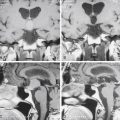
Various other conditions must be considered in the differential diagnosis of trigeminal neuralgia. These include herpes zoster (postherpetic neuralgia), dental disease, orbital disease, temporomandibular dysfunction, and temporal arteritis, as well as post-traumatic neuralgias. None of these typically presents with the classic lancinating paroxysmal pain of trigeminal neuralgia. Once the clinical diagnosis of trigeminal neuralgia is made, magnetic resonance imaging (MRI) should be performed to rule out demyelinating disease, infection, inflammatory processes, vascular malformations, and neoplasms.
Medical Therapy
After the diagnosis of trigeminal neuralgia is made, a trial of 100 mg of carbamazepine given twice a day is initiated. The dose is increased by 100 mg every other day until pain control is achieved or toxicity develops. Patients are instructed to take this medication on a full stomach and to have monthly hematologic studies performed so that toxicity can be detected early. In this manner, good control of the pain can be achieved in the vast majority of patients.7,8 Patients who are allergic or intolerant to carbamazepine can be treated with phenytoin, oxcarbazepine, clonazepam, and baclofen. Although gabapentin is frequently promoted for this indication, no studies have been published showing its efficacy, and it has rarely proved useful in our clinical experience. Surgery is reserved for patients whose pain is refractory to medical treatment or who develop medication-related side effects.
Indications
If the patient meets the typical clinical picture and fails medical therapy, surgical treatment options include microvascular decompression, selective percutaneous lesioning (with radiofrequency thermal coagulation or glycerol chemoneurolysis), or stereotactic radiosurgery of the trigeminal nerve. It is our practice to explain the relative benefits and risks of the surgical treatment options and assist the patient in choosing among these procedures (Table 125-1). We believe that microvascular decompression is the procedure of choice for the treatment of trigeminal neuralgia in otherwise healthy and relatively young (generally younger than 70 years) patients.9
Table 125-1 Relative Benefits of Percutaneous Trigeminal Neurolysis, Radiosurgical Trigeminal Neurolysis, and Microvascular Decompression of the Trigeminal Nerve for the Treatment of Trigeminal Neuralgia
| Procedure | Benefits | Drawbacks |
|---|---|---|
| Percutaneous trigeminal neurolysis |
Operative Positioning
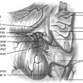
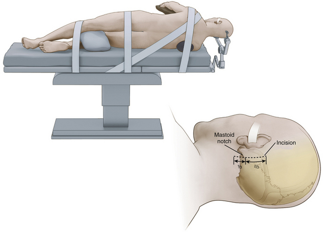
While we frequently use the sitting position for microvascular decompression procedures (as described in detail later), others often use a lateral or park bench position (Fig. 125-1).10 Briefly, for lateral or park bench positioning, the patient is induced, intubated, and placed under general anesthesia, and the head is secured in three-point pin fixation. The patient is then placed in the lateral decubitus position with the unaffected side down. A gel roll is placed in the axilla of the dependent side, all pressure points are padded, and the nondependent arm is supported by a padded armrest. The neck is then secured in a slightly flexed position, and the head is turned 10 to 20 degrees from the affected side to provide optimal exposure and a clear line of sight to the pathology during surgery. The vertex of the head is then positioned based on the site of vascular compression.10 For decompression of the fifth cranial nerve, the vertex of the head is maintained parallel to the floor. For decompression of the lower cranial nerves, the vertex of the head is turned 10 to 20 degrees toward the floor. The patient is secured to the operative table with 3-inch tape and/or Velcro straps, and the shoulder of the affected side can be gently taped caudally to provide additional working space. The remaining portions of the operation are similar to those described later, including incision, dural opening, intradural dissection/decompression, and closure.
Anesthetic Considerations
To detect air embolization, a Doppler precordial detector and an end-tidal carbon dioxide monitor are used because they can detect even minute amounts of air. This detection allows the anesthesiologist to raise the venous pressure and prevent further entrainment of air, avoiding massive air embolization. The effectiveness of these methods of intravenous air detection is such that we abandoned the use of central venous pressure catheters for this type of surgery. The central venous pressure catheter was originally inserted to allow the aspiration of air trapped in the right atrium. Small amounts of air, however, do not sequester in the atrium but pass through the heart into the pulmonary circulation. If detected at its earliest stages, raising the venous pressure to prevent further entrainment is sufficient.
Positioning Preferences
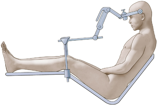
We achieve the sitting position using a pin-fixation head holder for rigid fixation of the skull. The patient’s head is rotated 15 to 30 degrees to the ipsilateral side. The head is flexed gently to provide ample room for placing one or two fingers beneath the patient’s chin (Fig. 125-2). The elevation (or angle) of the back of the table is such that the patient is actually in a semisitting or slouched position, although higher elevation of the backrest may be necessary in the older patient with a less flexible neck.
Operative Procedure
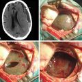
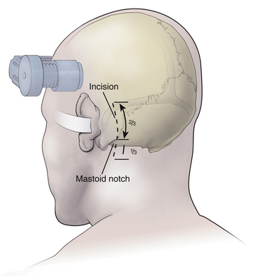
After the patient is satisfactorily anesthetized and positioned, the operative table is angled an additional 15 to 20 degrees to the ipsilateral side so that the surgeon approaches the patient at an angle of approximately 45 degrees from the midline. The hair is shaved only from the posterior quadrant of the head on the affected side, and sterile preparation and draping are performed. The incision is vertical and located 3 to 5 mm medial to the mastoid notch (Fig. 125-3). We use a linear incision approximately 8 cm long that is centered two thirds above and one third below the mastoid notch.
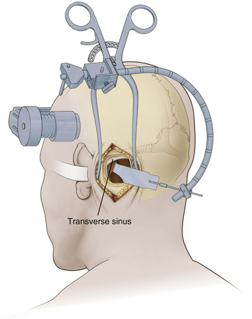
A modified Weitlaner retractor (Apfelbaum retractor) that serves as the base for a self-retaining brain retractor (Codman & Shurtleff, Raynham, MA) is then placed within the wound (Fig. 125-4). The retractor is secured by placing a gauze sponge through the loops of the handle and clipping it to the drape above the patient’s head to provide good three-point fixation and achieve adequate stability for the retractor arm. Several bur holes are made and enlarged into a circular craniectomy (2.5-3 cm) (Fig. 125-5). The craniectomy should extend superiorly to the transverse sinus and laterally to expose the sigmoid sinus. The lateral extension of the bony opening often carries the craniectomy over mastoid air cells, which are thoroughly waxed at the completion of the craniectomy. Care is taken to displace the dura as the rongeuring proceeds to avoid entering the dura or venous sinuses. Bridging veins may also be encountered and have to be coagulated.
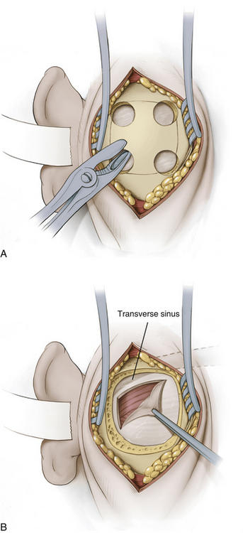
The dura then is opened in an inverted L-shaped manner 3 to 5 mm parallel to the sigmoid and transverse sinuses (Fig. 125-5). The dura can be further opened in a T shape at the superior corner if increased exposure is needed. The dura is then secured with tenting sutures superiorly and laterally to retract the sinuses slightly and complete the exposure.
Occasionally, adhesions or bridging vessels are encountered along the superior posterior margin of the cerebellum along the transverse sinus. These must be divided sharply to free the cerebellum. A flexible retractor arm is then placed on the retractor base. This retractor arm should be positioned so that a gentle arch is formed and sharp kinks and bends are avoided (Fig. 125-4). Its tension is adjusted so that it remains in any position in which it is placed but can be readily moved without undue force. A specially shaped retractor blade that has an elongated finger at its superior margin (Codman & Shurtleff) is used (Fig. 125-4). The purpose of the finger is to allow deeper retraction in the vicinity of the trigeminal nerve while avoiding deep retraction and potential injury to the seventh and eighth cranial nerves. A narrow retractor blade could achieve the same depth of exposure superiorly but might penetrate into the cerebellum. Once the retractor blade is in place, the superior lateral margin of the cerebellum is retracted in a medial-to-inferomedial direction, and the operating microscope is brought into use.
With the microscope in place, the cerebellum is gently retracted further medially. The approach should be angled as sharply as necessary to visualize the cerebellar surface. Adhesions and small bridging vessels are lysed as the cerebellum is retracted. Once the lateral extent of the cerebellum is visualized, the angle of approach is changed to follow the petrous bone anteriorly. McLaughlin et al.10 refer to this change as “turning the corner” and emphasize the necessity of doing this under direct vision. At this point, the petrosal vein can be identified. This vein frequently is encountered two thirds of the way from the dura to the trigeminal nerve, but great variability exists, and it may be absent or positioned close to the nerve. It often consists of two channels that form a Y-shaped bifurcation just before entering the dura. To permit adequate retraction and deeper dissection, the petrosal vein may need to be coagulated and divided sharply.
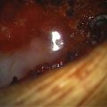
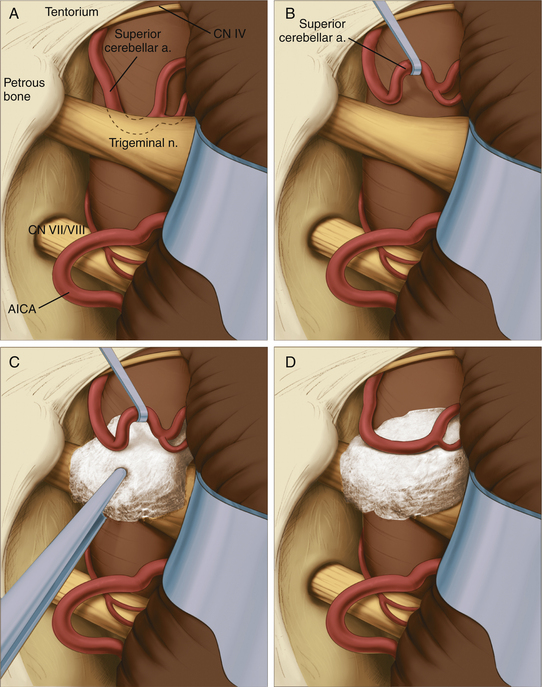
The site of pathology is typically at the brain stem, and vessels impinging distally on the nerve are not usually the cause of the problem. The typical situation involves the superior cerebellar artery looping down in front of the nerve and emerging from the nerve dorsally at the point where the nerve exits the brain stem (Fig. 125-6). Opening the arachnoid widely allows full inspection of the entire circumference of the nerve at the brain stem. The first vessel seen may not be the only vascular channel involved in the neurovascular compression, because in a significant number of cases, multiple vessels have been encountered. It is also necessary to open the arachnoid anterior to the nerve to allow proper placement of the prosthesis.
Jannetta microsurgical instruments (V. Mueller & Co., Chicago, IL), Rhoton dissectors (V. Mueller & Co.), or Apfelbaum dissectors (Integra Life Sciences, Plainsboro, NJ) are of sufficient length and properly fashioned to allow adequate vision throughout the operation. Various microsurgical scissors, including the Kurze left and right pistol-grip scissors (V. Mueller & Co.) and straight and angled bayoneted microscissors, are also employed. Once the arachnoid has been opened fully and the area has been inspected completely, the exact nature of the compression can be determined. A microdental mirror (warmed in hot saline to reduce fogging) may be useful in inspecting the region anterior to the nerve. This trigeminal nerve exposure is carried out directly over the seventh and eighth nerves (Fig. 125-6). The presence of these nerves must be kept in mind to avoid traumatizing them during the dissection or while inserting or removing instruments. The arterial loops that are found are then carefully dissected free of the trigeminal nerve.
When the superior cerebellar artery is the problem, the intent is to elevate it to a horizontal rather than vertical orientation and to displace it upward and away from the nerve (Fig. 125-6). This elongated vessel may have small branches going to the brain stem. Normally, these branches do not present a problem in the elevation of the vessel, as long as their position is kept in mind. Venous channels above or below the nerve are dissected away from the nerve and are coagulated and divided. The coagulation of these vessels is facilitated by the use of small up-and-down–angled bipolar forceps that prevent the spread of current to the adjacent neural structures. In the case of vessels compressing the nerve inferiorly, they must be displaced further inferiorly away from the nerve. In all cases, it is important to avoid kinking the arterial channels as they are repositioned.
To secure these vessels free of the nerve, a small prosthesis is inserted between the artery and the nerve (Fig. 125-6). For this purpose, we use either Ivalon or shredded Teflon felt. Ivalon, a synthetic polyvinyl formyl alcohol foam sponge material (Unipoint Industries, High Point, NC) has been safely used as a biologic implant for more than 30 years. This material comes packed in formalin and must be washed carefully to remove all traces of preservative. It can then be cut into small blocks and autoclaved. Before its use, Ivalon must be soaked for about 10 minutes in a saline solution to rehydrate it and allow it to become soft and pliable. A small block of the material is then carved to fit between the artery and the nerve. We usually fashion the block into a saddle-shaped structure so that it fits completely over the nerve. This structure effectively alters the arterial force vectors and creates a satisfactory decompression. In the case of a vessel inferior to the nerve, a similar type of sponge with a longer posterior element is fashioned, and this posterior element is inserted inferior to the nerve between the artery and the vein.
On several occasions, we created a sling using a partial thickness of the tentorium that was looped down around the vessel and reattached to the tentorium with a small suture. This was effective when the subarachnoid space was too cramped to place Ivalon without adding compression to the nerve but was technically much more difficult than inserting the sponge prosthesis. If venous channels alone are encountered, no prosthesis is required and the channels are coagulated and divided. Coagulation alone shrinks them, which increases the tension on the nerve and allows for potential recanalization, so the coagulated vessels should always be divided. Tumors can also be the sole cause of neural compression or found displacing a vessel against the nerve.
Operative Results
We analyzed our data in a consecutive series of 559 patients treated with microvascular decompression between November 1975 and June 2009. Some data points were not recorded in every case. Compression of the trigeminal nerve was found in 527 of 544 patients (97%) (Table 125-2). In 435 patients (78%), an artery was found compressing the nerve, most frequently the superior cerebellar artery (80%) (Table 125-3). In 6 cases (1%), an artery associated with a cerebellopontine angle tumor was found compressing the fifth cranial nerve, and in another 6 cases, the tumor itself was thought to be the compressing agent (Table 125-2). No compression of the nerve was identified in 17 patients (3%).
Table 125-2 Operative Findings in 559 Consecutive Patients Who Underwent Microvascular Decompression for Trigeminal Neuralgia
| Operative Finding | Patients |
|---|---|
| Arterial channels (alone, with veins, or AVM) | 435 (78%) |
| Venous channels alone | 80 (14%) |
| Tumor (6 with artery, 6 without artery) | 12 (2%) |
| No nerve compression | 17 (3%) |
| Not recorded | 15 (3%) |
| Total patients | 559 (100%) |
AVM, arteriovenous malformation.
Table 125-3 Compressing Artery Found at Surgery in 441 Patients∗ Who Underwent Microvascular Decompression for Trigeminal Neuralgia
| Artery Found | Patients |
|---|---|
| SCA | 351 (79.6%) |
| SCA and AICA | 39 (8.8%) |
| AICA | 39 (8.8%) |
| Basilar artery | 7 (1.6%) |
| Trigeminal nerve | 1 (<0.2%) |
| Vertebral artery | 1 (<0.2%) |
| Unnamed | 3 (<0.7%) |
| Total patients | 441 (<99.9%) |
SCA, superior cerebellar artery; AICA, anterior inferior cerebellar artery.
∗ Arterial compression either alone or in combination with veins, arteriovenous malformations, or tumors was noted in 441 patients. No such compression was noted in 118 of the 559 patients treated in the series.
Generally, our clinical results of this procedure correspond well with those of Jannetta as reported by Barker et al.4 Most patients awakened from anesthesia without tic pain, but some continued to postoperative pain for a few days or weeks (Table 125-4). This pain was less than that present immediately before surgery and gradually tapered off. Carbamazepine or phenytoin may be restarted for tic pain relief, if necessary, and then slowly tapered over a few weeks. In long-term follow-up (mean 75 months) of 501 consecutive patients who underwent microvascular decompression for refractory trigeminal neuralgia over more than 33 years (Table 125-5), the pain was controlled with or without medication in 416 (84%) patients. Of these patients, 22 (4%) had an occasional jab of pain but did not required any medication. An additional group of 68 patients (14%) required medication for full pain control after surgery. Before surgery, all of these patients had pain that was uncontrolled with maximal medical therapy. Although they did not experienced a perfect result, this group of patients greatly benefitted from the procedure. During this long follow-up period, 80 patients (16%) experienced severe recurrences that were refractory to medical therapy. These instances were failures of the procedure and necessitated an additional, usually destructive procedure to achieve relief.
Table 125-4 Initial Results Recorded in 523 Patients∗ Treated with Microvascular Decompression for Trigeminal Neuralgia
| Result | Patients |
|---|---|
| Complete relief | 474 (91%) |
| Immediate | 415 (79%) |
| At discharge | 27 (5%) |
| After discharge | 32 (6%) |
| Pain reduced | 32 (6%) |
| With medication | 23 (4%) |
| With additional surgery | 9 (2%) |
| Pain not relieved | 12 (2%) |
| Died | 5 (1%) |
| Total patients | 523 (100%) |
∗ Initial results were not available in 36 of the 559 patients treated in the series.
Table 125-5 Long-Term Results in 501 Patients∗ Treated with Microvascular Decompression for Trigeminal Neuralgia
| Result | Patients |
|---|---|
| No recurrence | 326 (65%) |
| Mild pain, no medication required | 22 (4%) |
| Pain medically controlled | 68 (14%) |
| Severe pain not controlled medically | 80 (16%) |
| Died | 5 (1%) |
| Total patients | 501 (100%) |
∗ Long-term results were not available in 58 of the 559 patients treated in the series.
Complications
The complications in our series are presented in Table 125-6. Five deaths occurred in this series, emphasizing the need for careful patient selection and screening. Cerebellar hemorrhagic infarction resulted in three deaths. We believe that this potentially lethal complication can be limited by minimizing the number of veins sacrificed at surgery. Although this may not be the only factor, since we have taken pains to spare the veins we have not had a death in the last 17 years. The most common type of complication is cranial nerve palsy. Transient facial numbness, which occurred in 19 patients (3%), and fourth nerve palsy, which occurred in 18 patients (3%), represent the most frequent of these. In all cases of fourth nerve palsy, the diplopia subsided over time (a few weeks to several months). Facial nerve palsy occurred in 8 patients (1%), and hearing loss occurred in 14 patients (3%). The facial nerve palsies that were severe were associated with cerebellopontine angle tumors in 4 of the 5 cases. The milder palsies were self-limited and resulted in good to satisfactory recovery. Hearing loss or disequilibrium may be caused by eighth nerve dysfunction. This was mild in 27 patients (5%) and severe in 14 patients (3%). Patients who develop hearing loss from eighth nerve dysfunction usually do not recover their hearing, although 1 of our patients did. This type of hearing loss must be distinguished from modest decreases in hearing that many patients experience immediately postoperatively because of fluid behind the eardrum (presumably tracking in through the mastoid area). This is a benign, self-limited process that clears spontaneously within a few weeks. Because we could not retrospectively distinguish these two, all are grouped under eighth nerve dysfunction.
Table 125-6 Complications in 559 Patients Treated with Microvascular Decompression for Trigeminal Neuralgia
| Complication | Patients |
|---|---|
| Death∗ | 5 (0.9%) |
| Cerebellar infarction∗ | 6 (1.1%) |
| Supratentorial infarction∗ | 3 (0.5%) |
| Brain stem infarction∗ | 1 (0.2%) |
| Focal seizures | 5 (0.9%) |
| Cranial nerve dysfunction | |
| Fourth nerve palsy (transient) | 18 (3.2%) |
| Sixth nerve palsy (transient) | 2 (<0.4%) |
| Seventh nerve palsy (permanent) | 5 (0.9%) |
| Seventh nerve palsy (transient) | 3 (0.5%) |
| Eighth nerve dysfunction | 21 (3.8%) |
| Facial numbness | 19 (3.4%) |
| Dizziness, disequilibrium, ataxia | 20 (3.6%) |
∗ Three deaths were from cerebellar infarction, and one each occurred from supratentorial infarction and brain stem infarction; these patients were included in the totals of the infarctions.
Conclusions
The Jannetta microvascular procedure, as detailed here, has proved effective in treating trigeminal neuralgia in most patients by treating the apparent cause of the problem rather than merely the symptoms. It offers the major advantage of sparing neural function and avoiding anesthesia dolorosa, other dysesthetic sensations, or facial sensory losses such as corneal anesthesia, but it carries with it a small risk of serious sequelae, including death.4,9,11 Although small but not insignificant risks are associated with this procedure, we believe that microvascular decompression remains the treatment of choice for trigeminal neuralgia.
Seventh Cranial Nerve
Clinical Presentation
The motor analogue of trigeminal neuralgia is hemifacial spasm, which is caused by vascular compression of the seventh cranial nerve. This disorder is less frequent than trigeminal neuralgia. We typically see five cases of trigeminal neuralgia for each case of hemifacial spasm. Females are more frequently affected than males (3:2 ratio). Although rare reports of this disorder in children exist, it is typically an adult disorder with a mean age of onset of 45 years.12
Patients with this condition suffer from repetitive, painless paroxysmal twitching of the facial muscles. Classically, this disorder starts with the muscles around the eyes and progresses slowly and insidiously to involve the middle and lower facial musculature. In severe cases, the spasm spreads to involve both the corrugator of the forehead and the platysma muscle on the anterior neck. At times, severe sustained contractures lasting for several seconds, the so-called tonus phenomenon, occur. The patient cannot voluntarily relax, so the contractures result in a grotesque disfigurement with a forced closure of the eye and a tight grimace of the mouth.
Electromyography can be used to help establish the diagnosis of hemifacial spasm. Electromyographic studies in cases of hemifacial spasm characteristically reveal 5 to 20 rhythmically occurring burst discharges per second, along with individual discharges and longer-lasting bursts. The rate of discharge of the latter may be as high as 150 to 250 bursts per second.13 These findings are pathognomic for hemifacial spasm and can help resolve any uncertainty about the diagnosis.
Preoperative Considerations
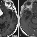
Once the diagnosis of hemifacial spasm is established by clinical and electrical evaluation, high-resolution MRI of the posterior fossa with and without contrast material should be obtained. Neoplasm, inflammation, infection, and non-neoplastic structural lesions that are revealed by thin-cut MRI studies should be treated accordingly. As in trigeminal neuralgia, the absence of a visualizable vascular loop on imaging does not rule out such a lesion. Preoperative and anesthetic considerations, as well as patient positioning, are identical to those described previously for trigeminal neuralgia. Intraoperative monitoring of the seventh (electromyography) and eighth (brain stem auditory evoked responses) cranial nerves is useful during this procedure.14,15
Operative Procedure
The incision is positioned so that half of the incision length is above the level of the mastoid notch (Fig. 125-3). The exposure of the occipital bone and the craniectomy are then performed as detailed previously. Similar to trigeminal nerve microvascular decompression, the craniectomy is extended laterally to expose the sigmoid sinus. Vertically, the craniectomy (Fig. 125-5) is extended superiorly to just below the transverse sinus and inferiorly to the floor of the posterior fossa. At this point, the bone is usually fairly thin and curves to extend almost straight away from the surgeon. It is important to not leave a lip on this area that will prevent the free egress of cerebrospinal fluid. The dura is opened in an L shape or reverse L shape 3 to 5 mm parallel to the sigmoid sinus and the floor of the posterior fossa, fairly close to these structures; if necessary, it can be further opened in a T shape. The dural edges are then secured with tenting sutures to widen the exposure.
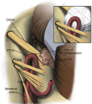
The same type of self-retaining retractor system is used, but the retractor blade is arced from side to side and tapers in width (Aesculap, Center Valley, PA). This retractor is placed beneath the cerebellum, and the cerebellum is elevated at its inferior lateral margin. The operating microscope, configured exactly as previously, is brought into use at this juncture. Under magnified vision, the cerebellum is gently elevated. It is important that the cerebellum is elevated by retracting upward on it rather than retracting it from lateral to medial. The latter may cause traction injuries to the seventh and eighth nerves. A Cottonoid strip is then placed along the medial inferior edge of the exposure to act as a wick that facilitates drainage of cerebrospinal fluid and prevents it from welling up in the operative field. With elevation of the cerebellum, the retractor can be advanced anteriorly under direct vision until the spinal part of cranial nerve XI comes into view. The arachnoid at this area is opened sharply, which allows further elevation of the cerebellum and exposure of the remaining nerves of the jugular foramen (Fig. 125-7). Occasionally, minute bridging veins have to be coagulated and divided to cause this exposure. Once the ninth cranial nerve, which is usually slightly separated from nerves X and XI, is identified, the exposure is carried medially by sequentially dividing the arachnoid (using sharp dissection) between the ninth nerve and the cerebellum.
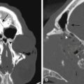
The site of cross-compression is found in this region where the seventh nerve leaves the brain stem. Several vessels have been encountered in our experience (Table 125-7). The anterior inferior cerebellar artery may loop up against the nerve and then continue either laterally or inferiorly. The posterior inferior cerebellar artery likewise can loop up to compress this area before taking a more inferior course. An ectatic vertebral artery can sometimes cause the same problem. On one occasion, an indentation of the nerve was noted, but no definite vascular channel was found. On closer inspection, an exostotic protuberance from the floor of the posterior fossa was noted, and when the retractor was released, it could be seen that this protuberance mated with the indentation on the nerve. In this instance, the protuberance was removed with a high-speed diamond drill to bring about relief.
Table 125-7 Operative Findings in 73 Consecutive Patients Who Underwent Microvascular Decompression for Treatment of Hemifacial Spasm
| Cause of Seventh Nerve Compression | Patients |
|---|---|
| Loop of AICA | 29 (39.7%) |
| Loop of PICA | 22 (30.1%) |
| Vertebral artery at AICA origin | 7 (9.6%) |
| Vertebral artery at PICA origin | 4 (5.5%) |
| Vertebral artery exclusively | 4 (5.5%) |
| AICA and PICA | 3 (4.1%) |
| Vein | 2 (2.7%) |
| Aneurysm | 1 (1.4%) |
| Bone exostosis | 1 (1.4%) |
| Total patients | 73 (99%) |
AICA, anterior inferior cerebellar artery; PICA, posterior inferior cerebellar artery.
When a vessel is encountered, it must be carefully dissected free of the nerve and placed in such a way that relieves the pressure on the nerve, while not kinking or compromising the vessel. Small tethering branches to the brain stem often limit the degree of displacement that can be achieved. The surgeon must always be aware of the possible presence of small branches along the medial side of the vessel going to the brain stem, especially at the apex of loops. After carefully dissecting the vessel free of the nerve and using the utmost care not to manipulate either the seventh or the eighth nerve, an Ivalon sponge prosthesis is fashioned to fit between the two. This sponge often takes on a complicated shape because of the limited access in this area and the necessity of accommodating various structures. We try to interdigitate the prosthesis between the vessels and often fashion protuberances on it to fit within the loops of the vessel to help anchor it in place. Alternatively, shredded Teflon felt can be used; it is softer and easier to manipulate. It may be less likely to compress the adjacent nerves and less likely to compromise the vessel and its branches. The Teflon felt should be shredded to a cotton ball–like consistency (Fig. 125-7), because it provides inadequate cushioning and is easily displaced when employed in sheet form. Absorbable materials, such as a Gelfoam sponge, should be avoided because the vessel may return to its compressive position against the nerve upon absorption. Similarly, muscle, which is attractive because it is easy to insert, has led to recurrences as the muscle atrophied under the continued arterial pulsations and allowed the artery and nerve to come into contact again.
Operative Results
In 73 consecutive cases, a cause of compression was identified in each situation. No negative explorations were encountered (Table 125-7). The most common cause of arterial compression was the anterior inferior cerebellar artery (40%), followed by the posterior inferior cerebellar artery (30%) (Table 125-7).
Generally, our clinical results are similar to those of Barker et al.16 and Samii et al.17 In our series, hemifacial spasm was relieved in all patients after microvascular decompression (Table 125-8). Of 67 patients (92% of the total in the series), 6 patients (8%) had good relief and 61 patients (84%) had complete relief of spasm in long-term follow-up (mean follow-up 8.8 years). All patients who had long-term follow-up, 70 patients (96%) from the series, had a greater than 50% reduction in twitches.
Table 125-8 Long-Term Results (Mean Follow-Up 8.8 Years) in 73 Consecutive Patients Who Underwent Microvascular Decompression for Treatment of Hemifacial Spasm
| Result | Patients |
|---|---|
| Excellent (complete resolution of symptoms) | 61 (84%) |
| Good (rare residual twitches) | 6 (8%) |
| Fair (50% reduction in twitches) | 3 (4%) |
| Poor (return of preoperative symptoms) | 0 (0%) |
| Unavailable | 3 (4%) |
| Total patients | 73 (100%) |
Complications
Most complications resulted in transient neurologic deficits or dysfunction (Table 125-9). Transient problems included facial weakness (11 patients), focal seizures (2 patients), and supratentorial stroke (1 patient). The transient facial weakness began in 6 patients 1 week after surgery. Of these patients, 3 had trace weakness that could only be detected with careful examination. The other 3 patients developed moderate (1 patient) or severe facial weakness (2 patients) that resolved over 2 to 6 months. In addition, 2 patients had new onset focal seizures at 1 and 6 months postoperatively. One patient had a supratentorial stroke and recovered completely. Three complications resulted in permanent deficits (Table 125-9), including quadriplegia secondary to a brain stem infarct (1 patient) and moderate hearing loss (2 patients).
Table 125-9 Complications in 73 Consecutive Patients Who Underwent Microvascular Decompression of the Seventh Cranial Nerve for Treatment of Hemifacial Spasm
| Complication | Patients |
|---|---|
| Permanent | |
| Brain stem stroke (quadriplegia) | 1 (2%) |
| Unilateral hearing loss | 2 (3%) |
| Transient | |
| Facial weakness | |
| Trace | 8 (11%) |
| Moderate | 1 (1%) |
| Severe | 2 (3%) |
| Focal seizure | 2 (3%) |
| Supratentorial stroke | 1 (1%) |
Fifth and Seventh Cranial Nerves
Cushing18 described a few patients suffering from the combined clinical picture of trigeminal neuralgia and hemifacial spasm, a condition that he termed tic convulsif. In patients who appear to have features of both trigeminal neuralgia and hemifacial spasm, it is appropriate to explore the root entry zone of both the fifth and the seventh cranial nerves.19 Although vascular channels compressing on both nerves should be anticipated, it is conceivable that only one nerve will be affected because of anomalous innervation. It is always the safest course to explore both nerves.
Ninth Cranial Nerve
Clinical Presentation
Glossopharyngeal neuralgia is a condition that is analogous to trigeminal neuralgia occurring in the ninth cranial nerve territory. The incidence of these two disorders differs greatly, with glossopharyngeal neuralgia being much less common than trigeminal neuralgia. Females are more commonly affected than males (2:1).20 The onset of symptoms is typically between 40 and 60 years of age, with a peak incidence in the fifth decade.20
This disorder has been classified into two groups based on the origin of pain. Patients with the tympanic form have pain that starts in the region of the ear and radiates to the throat, whereas patients with the oropharyngeal form have pain that begins in the throat and radiates to the ear. Despite differences in the origin of pain, patients classically describe the pain as a paroxysmal shooting, stabbing, or lancinating. Both sides of the face and throat are equally affected.20 Consistent with the close anatomic proximity of the vagal system, cases in which paroxysms have been associated with bradycardia, syncope, and occasionally asystole have been reported. The paroxysms are frequently triggered swallowing cold beverages but can be precipitated by yawning, talking, chewing, coughing, sneezing, or touching in the region of the tragus. These episodic attacks often occur in clusters that last from days to months and frequently relapse.
Operative Results
Because of the rare occurrence of glossopharyngeal neuralgia, few large series with long-term follow-up have evaluated the efficacy of microvascular decompression for this disorder.20–22 In 2002, Patel et al.20 reported the efficacy of microvascular decompression for glossopharyngeal neuralgia in 217 patients. This study found that immediately after surgery 67% of patients had complete relief and an additional 25% had partial relief, for an immediate postoperative success rate of 92%. Of the 50 patients with long-term follow-up (mean follow-up 4 years), 58% had complete relief of symptoms, 18% had partial relief (minimum of four-point improvement on a continuous pain scale, with or without medications), and 24% had a lack of substantial improvement. Moreover, this study found that isolated throat pain was a positive predictor of operative success.
Complications
In the series reported by Patel et al.,20 the rates of various complications were broken down into quartiles of approximately 50 patients over the period extending from 1973 to 2000. Various complications, including intracranial hematoma (rate of 0%-5.8% over quartiles), brain stem infarction (0%-4.1%), cranial nerve IX/X palsy (0%-4.2%), eighth/other cranial nerve palsy (0%-4.2%), cerebrospinal fluid leak (1.5%-5.8%), operative-related death (0%-5.8%), and dysphagia (0%-4.2%), were observed.
Apfelbaum R.I. Neurovascular decompression: the procedure of choice? Clin Neurosurg. 2000;46:473-498.
Barker F.G.2nd, Jannetta P.J., Bissonette D.J., et al. The long-term outcome of microvascular decompression for trigeminal neuralgia. N Engl J Med. 1996;334:1077-1083.
Barker F.G.2nd, Jannetta P.J., Bissonette D.J., et al. Microvascular decompression for hemifacial spasm. J Neurosurg. 1995;82:201-210.
Burchiel K.J., Slavin K.V. On the natural history of trigeminal neuralgia. Neurosurgery. 2000;46:152-155.
Campbell F.G., Graham J.G., Zilkha K.J. Clinical trial of carbazepine (Tegretol) in trigeminal neuralgia. J Neurol Neurosurg Psychiatry. 1966;29:265-267.
Cook B.R., Jannetta P.J. Tic convulsif: results in 11 cases treated with microvascular decompression of the fifth and seventh cranial nerves. J Neurosurg. 1984;61:949-951.
Cushing H. The major trigeminal neuralgias and their surgical treatment based on experiences with 332 gasserian operations. Am J Med Sci. 1920;160:157-184.
Dandy W. The treatment of trigeminal neuralgia by the cerebellar route. Ann Surg. 1932;96:787.
Digre K., Corbett J.J. Hemifacial spasm: differential diagnosis, mechanism, and treatment. Adv Neurol. 1988;49:151-176.
Gardner W., Sava G. Hemifacial spasm: a reversible pathophysiologic state. J Neurosurg. 1962;19:240-247.
Jannetta P.J. Arterial compression of the trigeminal nerve at the pons in patients with trigeminal neuralgia. J Neurosurg. 1967;26(suppl):159-162.
Jensen T.S., Rasmussen P., Reske-Nielsen E. Association of trigeminal neuralgia with multiple sclerosis: clinical and pathologic features. Acta Neurol Scand. 1982;65:182-189.
Kalkanis S.N., Eskander E.N., Carter B.S., et al. Microvascular decompression surgery in the United States, 1996 to 2000: mortality rates, morbidity rates, and the effects of hospital and surgeon volumes. Neurosurgery. 2003;52:1251-1262.
Kondo A. Follow-up results of using microvascular decompression for treatment of glossopharyngeal neuralgia. J Neurosurg. 1998;88:221-225.
Magun R., Esslen E. Electromyographic study of reinnervated muscle and of hemifacial spasm. Am J Phys Med Rehabil. 1959;38:79-86.
McLaughlin M.R., Jannetta P.J., Clyde B.L., et al. Microvascular decompression of cranial nerves: lessons learned after 4400 operations. J Neurosurg. 1999;90:1-8.
Mooij J.J.A., Mustafa M.K., van Weerden T.W. Hemifacial spasm: intraoperative electromyographic monitoring as a guide for microvascular decompression. Neurosurgery. 2001;49:1365-1371.
Patel A., Kassam A., Horowitz M., et al. Microvascular decompression in the management of glossopharyngeal neuralgia: analysis of 217 cases. Neurosurgery. 2002;50:705-711.
Polo G., Fischer C., Sindou M.P., et al. Brainstem auditory evoked potential monitoring during microvascular decompression for hemifacial spasm: intraoperative brainstem auditory evoked potential changes and warning values to prevent hearing loss—prospective study in a consecutive series of 84 patients. Neurosurgery. 2004;54:97-106.
Resnick D.K., Jannetta P.J., Bissonnette D., et al. Microvascular decompression for glossopharyngeal neuralgia. Neurosurgery. 1995;36:64-68. discussion 68-69
Rockliff B.W., Davis E.H. Controlled sequential trials of carbamazepine in trigeminal neuralgia. Arch Neurol. 1966;15:129-136.
Samii M., Gunther T., Iaconetta G., et al. Microvascular decompression to treat hemifacial spasm: long-term results for a consecutive series of 143 patients. Neurosurgery. 2002;50:712-719.
1. Dandy W. The treatment of trigeminal neuralgia by the cerebellar route. Ann Surg. 1932;96:787.
2. Gardner W., Sava G. Hemifacial spasm: a reversible pathophysiologic state. J Neurosurg. 1962;19:240-247.
3. Jannetta P.J. Arterial compression of the trigeminal nerve at the pons in patients with trigeminal neuralgia. J Neurosurg. 1967;26(suppl):159-162.
4. Barker F.G.2nd, Jannetta P.J., Bissonette D.J., et al. The long-term outcome of microvascular decompression for trigeminal neuralgia. N Engl J Med. 1996;334:1077-1083.
5. Burchiel K.J., Slavin K.V. On the natural history of trigeminal neuralgia. Neurosurgery. 2000;46:152-155.
6. Jensen T.S., Rasmussen P., Reske-Nielsen E. Association of trigeminal neuralgia with multiple sclerosis: clinical and pathologic features. Acta Neurol Scand. 1982;65:182-189.
7. Campbell F.G., Graham J.G., Zilkha K.J. Clinical trial of carbazepine (Tegretol) in trigeminal neuralgia. J Neurol Neurosurg Psychiatry. 1966;29:265-267.
8. Rockliff B.W., Davis E.H. Controlled sequential trials of carbamazepine in trigeminal neuralgia. Arch Neurol. 1966;15:129-136.
9. Apfelbaum R.I. Neurovascular decompression: the procedure of choice? Clin Neurosurg. 2000;46:473-498.
10. McLaughlin M.R., Jannetta P.J., Clyde B.L., et al. Microvascular decompression of cranial nerves: lessons learned after 4400 operations. J Neurosurg. 1999;90:1-8.
11. Kalkanis S.N., Eskander E.N., Carter B.S., et al. Microvascular decompression surgery in the United States, 1996 to 2000: mortality rates, morbidity rates, and the effects of hospital and surgeon volumes. Neurosurgery. 2003;52:1251-1262.
12. Digre K., Corbett J.J. Hemifacial spasm: differential diagnosis, mechanism, and treatment. Adv Neurol. 1988;49:151-176.
13. Magun R., Esslen E. Electromyographic study of reinnervated muscle and of hemifacial spasm. Am J Phys Med Rehabil. 1959;38:79-86.
14. Mooij J.J.A., Mustafa M.K., van Weerden T.W. Hemifacial spasm: intraoperative electromyographic monitoring as a guide for microvascular decompression. Neurosurgery. 2001;49:1365-1371.
15. Polo G., Fischer C., Sindou M.P., et al. Brainstem auditory evoked potential monitoring during microvascular decompression for hemifacial spasm: intraoperative brainstem auditory evoked potential changes and warning values to prevent hearing loss—prospective study in a consecutive series of 84 patients. Neurosurgery. 2004;54:97-106.
16. Barker F.G.2nd, Jannetta P.J., Bissonette D.J., et al. Microvascular decompression for hemifacial spasm. J Neurosurg. 1995;82:201-210.
17. Samii M., Gunther T., Iaconetta G., et al. Microvascular decompression to treat hemifacial spasm: long-term results for a consecutive series of 143 patients. Neurosurgery. 2002;50:712-719.
18. Cushing H. The major trigeminal neuralgias and their surgical treatment based on experiences with 332 gasserian operations. Am J Med Sci. 1920;160:157-184.
19. Cook B.R., Jannetta P.J. Tic convulsif: results in 11 cases treated with microvascular decompression of the fifth and seventh cranial nerves. J Neurosurg. 1984;61:949-951.
20. Patel A., Kassam A., Horowitz M., et al. Microvascular decompression in the management of glossopharyngeal neuralgia: analysis of 217 cases. Neurosurgery. 2002;50:705-711.
21. Resnick D.K., Jannetta P.J., Bissonnette D., et al. Microvascular decompression for glossopharyngeal neuralgia. Neurosurgery. 1995;36:64-68. discussion 68-69
22. Kondo A. Follow-up results of using microvascular decompression for treatment of glossopharyngeal neuralgia. J Neurosurg. 1998;88:221-225.