Medical gas supply
Cylinders
Components
1. Cylinders are made of thin-walled seamless molybdenum steel in which gases and vapours are stored under pressure. They are designed to withstand considerable internal pressure.
2. The top end of the cylinder is called the neck, and this ends in a tapered screw thread into which the valve is fitted. The thread is sealed with a material that melts if the cylinder is exposed to intense heat. This allows the gas to escape so reducing the risk of an explosion.
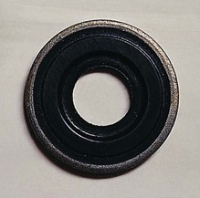
3. There is a plastic disc around the neck of the cylinder. The year when the cylinder was last examined can be identified from the shape and colour of the disc.
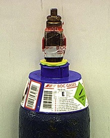
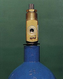
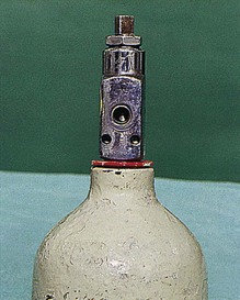
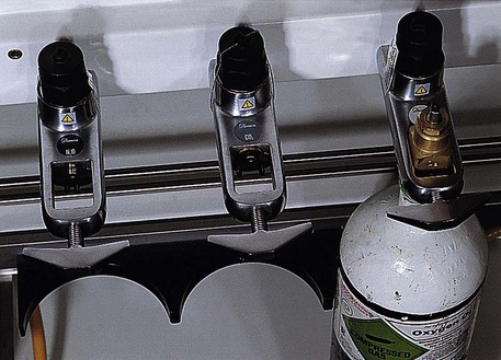
4. Cylinders are manufactured in different sizes (A to J). Sizes A and H are not used for medical gases. Cylinders attached to the anaesthetic machine are usually size E (Figs 1.1–1.4), while size J cylinders are commonly used for cylinder manifolds. Size E oxygen cylinders contain 680 L, whereas size E nitrous oxide cylinders can release 1800 L. The smallest sized cylinder, size C, can hold 1.2 L of water, and size E can hold 4.7 L while the larger size J can hold 47.2 L of water.
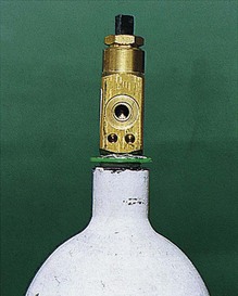
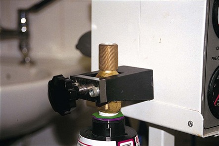
Fig. 1.2 Oxygen cylinder valve and pin index.
5. Lightweight cylinders can be made from aluminium alloy with a fibreglass covering in epoxy resin matrix. These can be used to provide oxygen at home, during transport or in magnetic resonance scanners. They have a flat base to help in storage and handling.
A full oxygen cylinder at atmospheric pressure can deliver 130 times its capacity of oxygen.
Problems in practice and safety features
1. The gases and vapours should be free of water vapour when stored in cylinders. Water vapour freezes and blocks the exit port when the temperature of the cylinder decreases on opening.
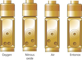
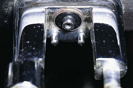
2. The outlet valve uses the pin-index system to make it almost impossible to connect a cylinder to the wrong yoke (Fig. 1.5).
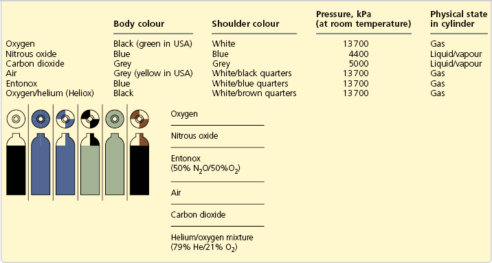
3. Cylinders are colour-coded to reduce accidental use of the wrong gas or vapour. In the UK, the colour-coding is a two-part colour, shoulder and body (Table 1.1). To improve safety, there are plans to change the colours of the bodies of cylinders using medical gas to white while keeping the colours of the shoulders according to the European Standard EN 1089-3.
4. Cylinders should be checked regularly while in use to ensure that they have sufficient content and that leaks do not occur.
5. Cylinders should be stored in a purpose built, dry, well-ventilated and fireproof room, preferably inside and not subjected to extremes of heat. They should not be stored near flammable materials such as oil or grease or near any source of heat. They should not be exposed to continuous dampness, corrosive chemicals or fumes. This can lead to corrosion of cylinders and their valves.
6. To avoid accidents, full cylinders should be stored separately from empty ones. F, G and J size cylinders are stored upright to avoid damage to the valves. C, D and E size cylinders can be stored horizontally on shelves made of a material that does not damage the surface of the cylinders.
7. Overpressurized cylinders are hazardous and should be reported to the manufacturer.
Cylinder valves
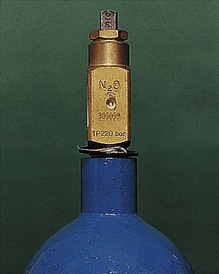
These valves seal the cylinder contents. The chemical formula of the particular gas is engraved on the valve (Fig. 1.6). Other types of valves, the bull nose, the hand wheel and the star, are used under special circumstances (Fig. 1.7).
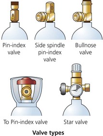
Fig. 1.7 Cylinder valves.
Components
1. The valve is mounted on the top of the cylinder, screwed into the neck via a threaded connection. It is made of brass and sometimes chromium plated.
2. An on/off spindle is used to open and close the valve by opposing a plastic facing against the valve seating.
3. The exit port for supplying gas to the apparatus (e.g. anaesthetic machine).
4. A safety relief device allows the discharge of cylinder contents to the atmosphere if the cylinder is overpressurized.
5. The non-interchangeable safety system (pin-index system) is used on cylinders of size E or smaller as well as on F- and G-size Entonox cylinders. A specific pin configuration exists for each medical gas on the yoke of the anaesthetic machine. The matching configuration of holes on the valve block allows only the correct gas cylinder to be fitted in the yoke (Figs 1.8 and 1.9). The gas exit port will not seal against the washer of the yoke unless the pins and holes are aligned.
6. A more recent modification is where the external part of the valve is designed to allow manual turning on and off of the cylinder without the need for a key (Fig. 1.10).
Problems in practice and safety features
1. The plastic wrapping of the valve should be removed just before use. The valve should be slightly opened and closed (cracked) before connecting the cylinder to the anaesthetic machine. This clears particles of dust, oil and grease from the exit port, which would otherwise enter the anaesthetic machine.
2. The valve should be opened slowly when attached to the anaesthetic machine or regulator. This prevents the rapid rise in pressure and the associated rise in temperature of the gas in the machine’s pipelines. The cylinder valve should be fully open when in use (the valve must be turned two full revolutions).
3. During closure, overtightening of the valve should be avoided. This might lead to damage to the seal between the valve and the cylinder neck.
4. The Bodok seal should be inspected for damage prior to use. Having a spare seal readily available is advisable.
Piped gas supply (piped medical gas and vacuum – PMGV)
Components
1. Central supply points such as cylinder banks or liquid oxygen storage tank.
2. Pipework made of special high-quality copper alloy, which both prevents degradation of the gases it contains and has bacteriostatic properties. The fittings used are made from brass and are brazed rather than soldered.
3. The size of the pipes differs according to the demand that they carry. Pipes with a 42 mm diameter are usually used for leaving the manifold. Smaller diameter tubes, such as 15 mm, are used after repeated branching.
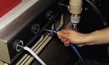
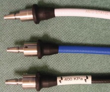
4. Outlets are identified by gas colour coding, gas name and by shape (Fig. 1.12). They accept matching quick connect/disconnect probes, Schrader sockets (Fig. 1.13), with an indexing collar specific for each gas (or gas mixture).
5. Outlets can be installed as flush-fitting units, surface-fitting units, on booms or pendants, or suspended on a hose and gang mounted (Fig. 1.14).
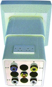
Fig. 1.14 Outlet sockets mounted in a retractable ceiling unit. (Courtesy of Penlon Ltd, Abingdon, UK (www.penlon.com).)
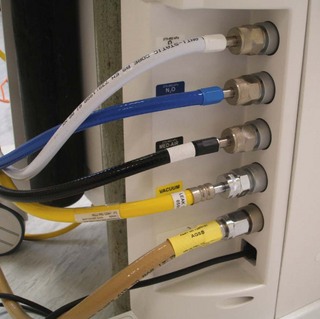
6. Flexible colour-coded hoses connect the outlets to the anaesthetic machine (Fig. 1.15). The anaesthetic machine end should be permanently fixed using a nut and liner union where the thread is gas specific and non-interchangeable (non-interchangeable screw thread, NIST, is the British Standard).
7. Isolating valves behind break glass covers are positioned at strategic points throughout the pipeline network. They are also known as area valve service units (AVSUs) (Fig. 1.16). They can be accessed to isolate the supply to an area in cases of fire or other emergency
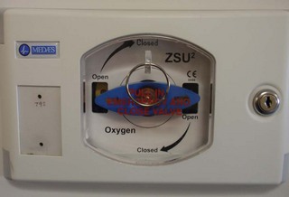
Fig. 1.16 An area valve service unit (AVSU).
Problems in practice and safety features
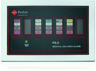
1. A reserve bank of cylinders is available should the primary supply fail. Low-pressure alarms detect gas supply failure (Fig. 1.17).
2. Single hose test is performed to detect cross-connection.
3. Tug test is performed to detect misconnection.
4. Regulations for PMGV installation, repair and modification are enforced.
5. Anaesthetists are responsible for the gases supplied from the terminal outlet through to the anaesthetic machine. Pharmacy, supplies and engineering departments share the responsibility for the gas pipelines ‘behind the wall’.
6. There is a risk of fire from worn or damaged hoses that are designed to carry gases under pressure from a primary source such as a cylinder or wall-mounted terminal to medical devices such as ventilators and anaesthetic machines. Because of heavy wear and tear, the risk of rupture is greatest in oxygen hoses used with transport devices. Regular inspection and replacement, every 2–5 years, of all medical gas hoses is recommended.
Sources of gas supply
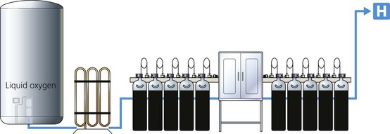
The source of supply can be cylinder manifold(s) and, in the case of oxygen, a liquid oxygen storage tank or oxygen concentrator (Fig. 1.18).
Manifolds are used to supply nitrous oxide, Entonox and oxygen.
Components
1. Large cylinders (e.g. size J each with 6800 L capacity) are usually divided into two equal groups, primary and secondary. The two groups alternate in supplying the pipelines (Fig. 1.19). The number of cylinders depends on the expected demand.
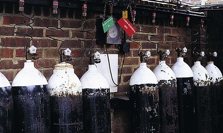
Fig. 1.19 An oxygen cylinder manifold.
2. All cylinders in each group are connected through non-return valves to a common pipe. This in turn is connected to the pipeline through pressure regulators.
3. As nitrous oxide is only available in cylinders (in contrast to liquid oxygen), its manifold is larger than that of oxygen. The latter usually acts as a back up to liquid oxygen supply (see later).
Mechanism of action
1. In either group, all the cylinders’ valves are opened. This allows them to empty simultaneously.
2. The supply is automatically changed to the secondary group when the primary group is nearly empty. The changeover is achieved through a pressure-sensitive device that detects when the cylinders are nearly empty.
3. The changeover activates an electrical signalling system to alert staff to the need to change the cylinders.
Liquid oxygen
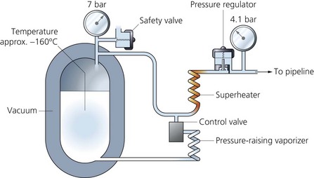
A vacuum-insulated evaporator (VIE) (Fig. 1.20) is the most economical way to store and supply oxygen.
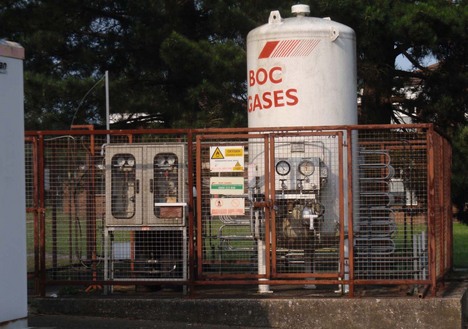
Fig. 1.20 A vacuum-insulated evaporator (VIE).
Components
1. A thermally insulated double-walled steel tank with a layer of perlite in a vacuum is used as the insulation (Fig. 1.21). It can be described as a giant thermos flask, employing the same principles.
2. A pressure regulator allows gas to enter the pipelines and maintains the pressure through the pipelines at about 400 kPa.
3. A safety valve opens at 1700 kPa allowing the gas to escape when there is a build-up of pressure within the vessel. This can be caused by underdemand for oxygen.
4. A control valve opens when there is an excessive demand on the system. This allows liquid oxygen to evaporate by passing through superheaters made of uninsulated coils of copper tubing.
Mechanism of action
1. Liquid oxygen is stored (up to 1500 L) at a temperature of −150° to −170°C (lower than the critical temperature) and at a pressure of 10.5 bars.
2. The temperature of the vessel is maintained by the high-vacuum shell. Evaporation of the liquid oxygen requires heat (latent heat of vaporization). This heat is taken from the liquid oxygen, helping to maintain its low temperature.
3. The storage vessel rests on a weighing balance to measure the mass of the liquid. More recently, a differential pressure gauge which measures the pressure difference between the bottom and top of the liquid oxygen can be used instead. The information obtained is sent to the hospital alarm system. As liquid oxygen evaporates, its mass decreases, reducing the pressure at the bottom. By measuring the difference in pressure, the contents of the VIE can be calculated. When required, fresh supplies of liquid oxygen are pumped from a tanker into the vessel.
4. The cold oxygen gas is warmed once outside the vessel in a coil of copper tubing. The increase in temperature causes an increase in pressure.
5. At a temperature of 15°C and atmospheric pressure, liquid oxygen can give 842 times its volume as gas.
Problems in practice and safety features
1. Reserve banks of cylinders are kept in case of supply failure.
2. A liquid oxygen storage vessel should be housed away from main buildings due to the fire hazard. The risk of fire is increased in cases of liquid spillage.
3. Spillage of cryogenic liquid can cause cold burns, frostbite and hypothermia.
Oxygen concentrators
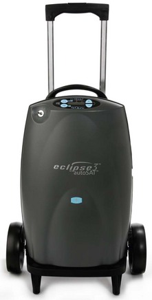
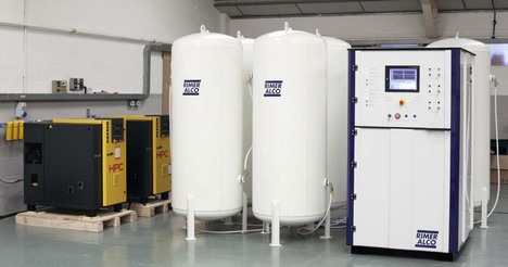
Oxygen concentrators, also known as pressure swing adsorption systems, extract oxygen from air by differential adsorption. These devices may be small, designed to supply oxygen to a single patient (Fig. 1.22), supply oxygen to an anaesthetic machine (Fig. 1.23) or they can be large enough to supply oxygen for a medical gas pipeline system (Fig. 1.24).
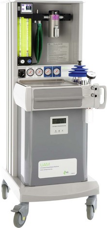
Fig. 1.23 The universal anaesthetic machine (UAM) which has a built-in oxygen concentrator (see Ch. 2 for more details). (Courtesy of UAM Global.)
Mechanism of action (Fig. 1.25)
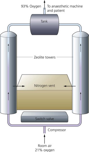
Fig. 1.25 Mechanism of action of a concentrator.
1. Ambient air is filtered and pressurized to about 137 kPa by a compressor.
2. Air is exposed to a zeolite molecular sieve column, forming a very large surface area, at a certain pressure.
3. The sieve selectively retains nitrogen and other unwanted components of air. These are released into the atmosphere after heating the column and applying a vacuum.
4. The changeover between columns is made by a time switch, typically cycles of around 20 seconds, allowing for a continuous supply of oxygen.
5. The maximum oxygen concentration achieved is 95% by volume. Argon is the main remaining constituent.
6. The life of the zeolite crystal can be expected to be at least 20 000 hours (which is about 10 years of use). Routine maintenance consists of changing filters at regular intervals.
Entonox (BOC Medical)
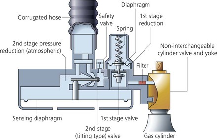
This is a compressed gas mixture containing 50% oxygen and 50% nitrous oxide by volume. It is commonly used in the casualty and labour ward settings to provide analgesia. A two-stage pressure demand regulator is attached to the Entonox cylinder when in use (Figs 1.26 and 1.27). As the patient inspires through the mask or mouth piece, gas flow is allowed to occur. Gas flow ceases at the end of an inspiratory effort. Entonox is compressed into cylinders to a pressure of 13 700 kPa. Entonox cylinders should be stored at 10°C for 24 hours before use.
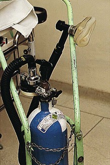
Fig. 1.26 An Entonox cylinder and delivery system.
• a liquid mixture containing mostly nitrous oxide with about 20% oxygen dissolved in it
• above the liquid, a gas mixture of high oxygen concentration.
Rewarming and mixing of both the cylinder and its contents reverses the separation and liquefaction.
Problems in practice and safety features
Liquefaction and separation of the components can be prevented by:
1. Cylinders being stored horizontally for about 24 hours at temperatures of or above 5°C before use. The horizontal position increases the area for diffusion. If the contents are well mixed by repeated inversion, cylinders can be used earlier than 24 hours.
2. Large cylinders are equipped with a dip tube with its tip ending in the liquid phase. This results in the liquid being used first, preventing the delivery of an oxygen concentration of less than 20%. Prolonged use of Entonox should be avoided because of the effect of nitrous oxide on the bone marrow especially in the critically ill patient. Adequate facilities for scavenging should be provided to protect hospital staff.
Compressed air
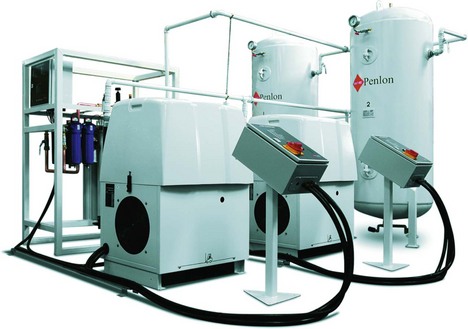
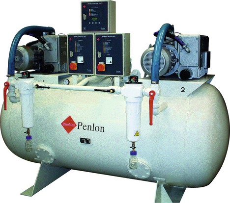
Air may be supplied from cylinder manifolds, or more economically from a compressor plant with duty and back-up compressors (Fig. 1.28). Oil-free medical air is cleaned by filters and separators and then dried before use.
Centralized vacuum or suction system (Fig. 1.29)
Mechanism of action
1. Negative pressure is generated by an electric motor and pneumatic-driven pumps using the Venturi principle.
2. The amount of vacuum generated can be manually adjusted by the suction controller. This device has a variable orifice with a float assembly, a back-up filter to prevent liquid entering the system and ports to connect to a collection vessel or reservoir through flexible tubing.
3. The reservoir must have sufficient capacity to receive the aspirated material. Too large a capacity will make the system cumbersome and will take a long time to generate adequate negative pressure.
4. The suction tubing should be flexible and firm to prevent collapse. Also it should be transparent so that the contents aspirated can be visualized, and of sufficient internal diameter and length for optimal suction.
5. The negative pressure (or degree of suctioning) can be adjusted to suit its use; e.g. a lesser degree of suctioning is required to clear oral secretions in a child than in an adult.
6. Bacterial filters are used to prevent spread of infectious bacteria, with a removal of 99.999% of bacteria. Filters are also used to prevent fluids, condensate and smoke from contaminating the system.
7. It is recommended that there are at least two vacuum outlets per each operating theatre, one per anaesthetic room and one per recovery or intensive care unit bed.
Health Technical Memorandum 2022. Medical gas pipeline systems. London: The Stationery Office; 1997.
Health Technical Memorandum 02-01. Medical gas pipeline systems, part A; design, installation, validation and verification. London: The Stationery Office; 2006.
Health Technical Memorandum 02-01. Medical gas pipeline systems, part B; operational management. London: The Stationery Office; 2006.
Highly D. Medical gases, their storage and delivery. Anaesthesia and Intensive Care Medicine. 2009;10(11):523–527.
MHRA. Medical device alert: anaesthetic machine: auxillary common gas outlet (ACGO) manufactured by GE Healthcare (MDA/2011/118). Online. Available at http://www.mhra.gov.uk/Publications/Safetywarnings/MedicalDeviceAlerts/CON137664, 2011.
National Health Service. Oxygen safety in hospitals. Online. Available at http://www.nrls.npsa.nhs.uk/resources/?entryid45=62811&p=7, 2009.
Poolacherla R., Nickells J. Suction devices. Anaesthesia and Intensive Care Medicine. 2006;7(10):354–355.
In the following lists, which of the statements (a) to (e) are true?
a) Oxygen is stored in cylinders as a gas.
b) The pressure in a half-filled oxygen cylinder is 13 700 kPa.
c) The pressure in a half-full nitrous oxide cylinder is 4400 kPa.
d) Nitrous oxide is stored in the cylinder in the gas phase.
a) Entonox is 50 : 50 mixture by weight of O2 and N2O.
b) Entonox has a critical temperature of 5.5°C.
c) Entonox cylinders should be stored upright.
d) At room temperature, Entonox cylinders contain only gas.
e) Entonox cylinders have blue bodies and white and blue quarters on the shoulders.
a) For medical use, oxygen is usually formed from fractional distillation of air.
b) Long-term use can cause bone marrow depression.
c) In hyperbaric concentrations, oxygen may cause convulsions.
d) At constant volume, the absolute pressure of oxygen is directly proportional to its absolute temperature.
a) Oxygen concentrators concentrate O2 that has been delivered from an oxygen cylinder manifold.
b) Argon accumulation can occur when oxygen concentrators are used with the circle system.
c) They are made of columns of a zeolite molecular sieve.
a) Oxygen is stored in cylinders at approximately 140 bars.
b) It has a critical temperature of 36.5°C.
c) It is a liquid in its cylinder.
a) The filling ratio = weight of liquid in the cylinder divided by the weight of water required to fill the cylinder.
b) The tare weight is the weight of the cylinder plus its contents.
c) Nitrous oxide cylinders have a blue body and blue and white top.
d) A full oxygen cylinder has a pressure of approximately 137 bars.
e) At 40°C, a nitrous oxide cylinder contains both liquid and vapour.
7. Concerning piped gas supply in the operating theatre:
a) Compressed air is supplied only under one pressure.
b) The NIST system is the British Standard.
c) Only oxygen and air are supplied.
d) E-size cylinders are normally used in cylinder manifolds.
a) There is no need for cylinders to undergo regular checks.
b) The only agent identification on the cylinder is its colour.
c) When attached to the anaesthetic machine, the cylinder valve should be opened slowly.
d) When warmed, liquid oxygen can give 842 times its volume as gas.
e) Cylinders are made of thick-walled steel to withstand the high internal pressure.
a) True. Oxygen is stored in the cylinder as a gas.
b) False. Oxygen is stored as a gas in the cylinder where gas laws apply. The pressure gauge accurately reflects the contents of the cylinder. A full oxygen cylinder has a pressure of 13 700 kPa. Pressure in a half-full oxygen cylinder is therefore 6850 kPa.
c) True. Nitrous oxide is stored in the cylinder in the liquid form. The pressure of a full nitrous oxide cylinder is about 4400 kPa. As the cylinder is used, the vapour above the liquid is used first. This vapour is replaced by new vapour from the liquid. Therefore the pressure is maintained. So the cylinder is nearly empty before the pressure starts to decrease. For this reason, the pressure gauge does not accurately reflect the contents of the cylinder.
d) False. Nitrous oxide is stored in the cylinder as a liquid. The vapour above the liquid is delivered to the patient.
e) True. Entonox is a compressed gas mixture containing 50% oxygen and 50% nitrous oxide by volume.
a) False. Entonox is a 50 : 50 mixture of O2 and N2O by volume and not by weight.
b) False. The critical temperature of Entonox is −5.5°C. At or below this temperature, liquefaction and separation of the two components occurs. This results in a liquid mixture of mainly nitrous oxide and about 20% oxygen. Above the liquid is a gaseous mixture with a high concentration of oxygen.
c) False. This increases the risk of liquefaction and separation of the components. To prevent this, Entonox cylinders should be stored horizontally for about 24 hours at temperatures at or above 5°C. This position increases the area for diffusion. With repeated inversion, Entonox cylinders can be used earlier than 24 hours.
d) True. Liquefaction and separation of nitrous oxide and oxygen occurs at or below −5.5°C.
a) True. Except for oxygen concentrators which use zeolites.
b) False. Long-term use of oxygen has no effect on the bone marrow. Long-term use of N2O can cause bone marrow depression especially with high concentrations in critically ill patients.
d) True. This is Gay–Lussac’s law where pressure = constant × temperature. Oxygen also obeys the other gas laws (Dalton’s law of partial pressures, Boyle’s and Charles’s laws).
e) True. At or below −118°C, oxygen changes to the liquid phase. This is used in the design of the vacuum insulated evaporator where oxygen is stored in the liquid phase at temperatures of −150 to −170°C.
a) False. Oxygen concentrators extract oxygen from air using a zeolite molecular sieve. Many columns of zeolite are used. Zeolites are hydrated aluminium silicates of the alkaline earth metals.
b) True. The maximum oxygen concentration achieved by oxygen concentrators is 95%. The rest is mainly argon. Using low flows with the circle breathing system can lead to the accumulation of argon. Higher fresh gas flows are required to avoid this.
c) True. The zeolite molecular sieve selectively retains nitrogen and other unwanted gases in air. These are released into the atmosphere. The changeover between columns is made by a time switch.
d) False. Oxygen concentrators can deliver a maximum oxygen concentration of 95%.
e) False. Oxygen concentrators can be small, delivering oxygen to a single patient, or they can be large enough to supply oxygen to hospitals.
a) True. Molybdenum steel or aluminium alloy cylinders are used to store oxygen at pressures of approximately 14 000 kVa (140 bars).
b) False. The critical temperature of O2 is −118°C. Above that temperature, oxygen cannot be liquefied however much pressure is applied.
c) False. Oxygen is a gas in the cylinder as its critical temperature is −118°C.
d) True. Oil is flammable while oxygen aids combustion. Oxygen cylinders should be stored away from oil.
e) True. At a constant temperature, the volume of a given mass of oxygen varies inversely with the absolute pressure (volume = constant × 1/pressure). Oxygen obeys other gas laws.
a) True. The filling ratio is used when filling cylinders with liquid, e.g. nitrous oxide. As the liquid is less compressible than the gas, the cylinder should be only partially filled. Depending on the ambient temperature, the filling ratio can be from 0.67 to 0.75.
b) False. The tare weight is the weight of the empty cylinder. This is used to estimate the amount of the contents of the cylinder. It is one of the marks engraved on the cylinders.
c) False. Nitrous oxide cylinders have a blue body and top. Entonox cylinders have a blue body and blue and white top.
e) False. At 40°C, nitrous oxide exists as a gas only. This is above its critical temperature, 36.5°C, so it cannot be liquefied above that.
7. Concerning piped gas supply in the operating theatre:
a) False. Air is supplied at two different pressures; at 400 kVa when it is delivered to the patient and at 700 kPa when used to operate power tools in the operating theatre.
b) True. This stands for non-interchangeable screw thread. This is one of the safety features present in the piped gas supply system. Flexible colour-coded hoses connect the outlets to the anaesthetic machine. The connections to the anaesthetic machine should be permanently fixed using a nut and liner union where the thread is gas-specific and non-interchangeable.
c) False. Oxygen, nitrous oxide, air and vacuum can be supplied by the piped gas system.
d) False. Larger cylinders, e.g. J size, are normally used in a cylinder manifold. E-size cylinders are usually mounted on the anaesthetic machine.
e) False. Liquid oxygen has to be stored at temperatures below its critical temperature, −118°C. So oxygen stored at temperatures above −100°C (above its critical temperature) exists as a gas.
a) False. Cylinders should be checked regularly by the manufacturers. Internal endoscopic examination, pressure testing, flattening, bending and impact testing and tensile testing are done on a regular basis.
b) False. To identify the agent, the name, chemical symbol, pharmaceutical form and specification of the agent, in addition to the colour of the cylinder are used.
c) True. When attached to an anaesthetic machine, the cylinder valve should be opened slowly to prevent the rapid rise in pressure within the machine’s pipelines.
d) True. It is more economical to store oxygen as liquid before supplying it. At a temperature of 15°C and atmospheric pressure, liquid oxygen can give 842 times its volume as gas.
e) False. For ease of transport, cylinders are made of thin-walled seamless molybdenum steel. They are designed to withstand considerable internal pressures and tested up to pressures of about 22 000 kPa.

