[level-membership-for-anesthesiology-category]
Chapter 2 Measurement of pressure and gas flow
Force, pressure and flow
Pressure is force per unit area over which the force acts, i.e.
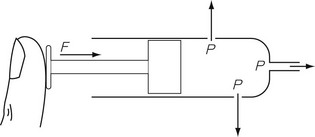
In any gas or liquid, pressure acts in all directions equally, whereas force acts in a given direction. For example, in a full hypodermic syringe, the liquid can be pressurized by applying a force to the plunger of the syringe. This is applied in the direction of travel of the plunger. However, if there were a leak in the barrel of the syringe, the liquid would squirt out sideways from the leak, as well as from the syringe outlet (Fig. 2.1), due to the pressure created by the force acting in all directions within the barrel of the syringe. The amount of pressure generated depends on the area of cross section of the barrel since it is over this area that the force acts. Thus, the pressure generated in a syringe with a small bore is higher than that generated in a syringe with a large bore for the same force applied to the plunger.
All the individual gas laws, i.e. Boyle’s Law, Charles’s Law and Gay Lussac’s Law, can be summarized in the equation below using the Ideal Gas Law which relates the pressure and volume of a given mass of gas to its temperature:

where P is the pressure of the gas, V its volume, T its temperature, R a constant and n the number of moles of gas present. Measuring the change in the number of moles (n) of a gas in a stream gives a measurement of the number of atoms moving in the flow and is called Molar or Mass Flow.
Atmospheric pressure and partial pressure
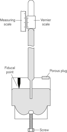
The definition of bar given above shows that the air exerts a pressure called atmospheric pressure. Atmospheric pressure is measured using a barometer, the simplest form of which is the Fortin barometer (Fig. 2.2). This consists of a long transparent tube, sealed at one end, which is filled with mercury and inverted with its open end in a bath of mercury exposed to atmospheric pressure. The atmospheric pressure acting on the surface of the mercury in the bath will support a column of mercury of about 760 mm above the surface of the mercury in the bath, leaving a virtual vacuum between the surface of the mercury in the tube and the sealed tube end. The height of column of mercury is measured using a Vernier scale at the top of the tube, which can be adjusted using a knob next to the barometer tube.
Partial pressure
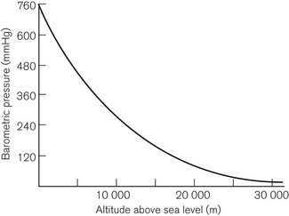
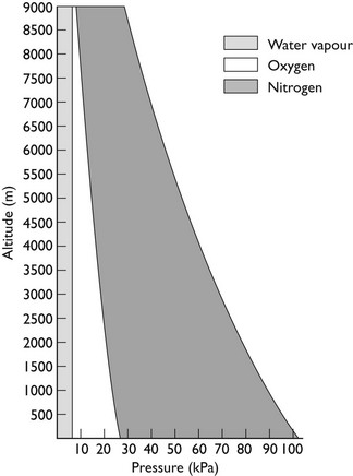
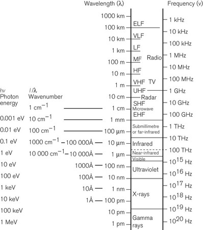
This is Dalton’s Law of Partial Pressures and shows that each gas exerts its own partial pressure independent of its companions. For example, if air is 20% oxygen and 80% nitrogen, then for an atmospheric pressure of 760 mmHg, the partial pressure of oxygen will be 152 mmHg and the partial pressure of nitrogen will be 608 mmHg. However, as Figure 2.3 shows, barometric pressure falls with altitude. Thus, when treating a patient at high altitude, a larger percentage of oxygen is required to supply the same partial pressure of oxygen. It is this partial pressure, not percentage of gas, which is clinically most important. The relationship between altitude and the partial pressure of the components of atmospheric air is shown in Figure 2.4.
Absolute, differential and gauge pressures
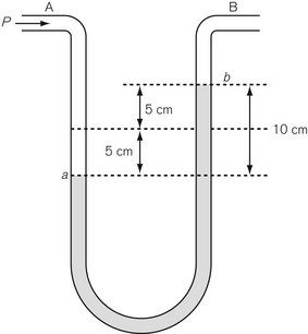
Differential pressure measurement is used where the difference in pressure between two points is required. The simplest differential pressure measurement system is the manometer, as shown in Figure 2.5. This takes the form of a U-shaped tube, partially filled with liquid such as water. Gas at pressure P is applied to end A, with end B open to the atmosphere (so having atmospheric pressure applied to it). The pressure at A causes water to be pushed to the other limb of the U so that the level in the right-hand limb moves to point b above where it was before the pressure was applied, and the water in the left-hand limb is depressed below its original level. If both move by a distance of 5 cm then the difference in water level created is 10 cm, indicating a pressure difference between A and B of 10 cmH2O. Since the end B is open to atmosphere, the pressure at A can be thought of as being above atmospheric and is referred to as gauge pressure and is sometimes denoted by placing a ‘g’ after the pressure unit, e.g 10 cmH2O g. If the ends A and B are at different points within a closed system, such as between the pleural cavity and the alveoli, then the pressure measured is a true differential pressure.
Methods of measuring pressure
Mechanical methods
Bourdon gauge
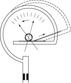
The Bourdon gauge (Fig. 2.6) is robust, inexpensive and can withstand high pressures. It consists of a curved flattened tube, elliptical in section. When pressure is applied, the tube expands and in doing so attempts to straighten out. Levers, gears or a rack and pinion mechanism translate this movement to a dial pointer. The inlet has a constriction within it to protect the gauge from sudden increases in applied pressure. This gauge is normally used in anaesthesia to indicate cylinder and pipeline pressures. In this application, the pressures measured are much greater than atmospheric pressure. As the response to the applied pressure is determined by the mechanical properties of the Bourdon gauge tube, it effectively measures absolute pressure.
Aneroid gauge
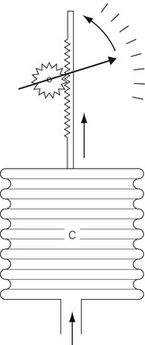
The mechanical principles of an aneroid gauge are shown in Fig. 2.7. It measures absolute pressure and, as with the Bourdon gauge, the movement generated by application of pressure to a chamber is translated into movement of a dial by a mechanical linkage. The amount of movement generated is controlled by the compliance of the aneroid chamber so that the more rigid the chamber the higher the pressure that the gauge will indicate. The sensitivity of the gauge can be controlled by the gearing ratio of the rack and pinion. Where encountered in anaesthetic devices, aneroid gauges are relatively delicate and sensitive but able to indicate low pressures. They may be used to measure airway pressure or blood pressure. If the chamber is sealed and evacuated, the gauge becomes the familiar aneroid barometer. Electronic sensors of pressure have largely superseded the aneroid gauge.
Electronic methods
Solid-state electronic pressure transducers
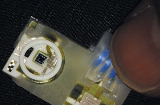
Electronic pressure gauges (transducers) are now the commonest method for the measurement of pressure and (in modified forms) force, in anaesthetic machines and devices such as blood pressure machines or infusion pumps. They can be used for both absolute measurements and differential measurement, depending on how they are housed and mounted. A typical solid-state electronic pressure transducer is shown in Fig. 2.8.
When used as an absolute pressure monitor, the transducer is mounted within a chamber and is isolated from the medium in which the pressure is to be measured by a flexible membrane such as a colloid gel to prevent contamination or loss of performance caused by the medium. The sensitivity and pressure measurement range of the transducer is determined by the inherent sensitivity of the piezoresistive transducer (see below). If used as a differential pressure transducer, the sensor is mounted so that each side of the transducer is connected to one of the two possible pressure inlets.
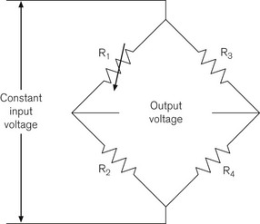
In a solid-state pressure transducer, a single piezoresistive strain gauge is formed on a thin single piece of silicon. The resistance of this strain gauge becomes higher or lower as the silicon slice is flexed by the applied pressure. The resistor is used as one of the four resistors of a Wheatstone bridge circuit (Fig. 2.9), where four resistances are placed in a diamond formation. The voltage difference across the bridge is zero, that is, the bridge is balanced when:

Measurement of gas flow
The measurement of gas flow is vital to anaesthesia and can be approached using a number of different physical principles. The practical flowmeters include those that respond to gas velocity, volumetric flow, gas momentum and mass flow. All are affected by whether the flow to be measured is laminar, turbulent or reciprocating. In some types of flowmeter, the design of the flowmeter itself ensures that the required flow regime is present, in others the operating flow conditions are set by the application. In addition to being sensitive to the flow regime, they are also affected by changes in gas composition. The latter makes the measurement of respiratory flows, where expiratory and inspiratory gas composition and humidity vary, inherently more difficult than the measurement of flow in dry, single-gas composition situations within anaesthetic machines. The correct selection of the type of flowmeter for the chosen application is thus essential. Table 2.1 shows the general characteristics upon which selection of a type of flowmeter depends.
Table 2.1 Characteristics of flow and volume measurement in anaesthesia
*NB Exhaled volumes should always be measured rather than inspiratory volumes, as then the anaesthetist always has an indication that at least this volume was previously inhaled despite any unanticipated leaks in the system.
Differential pressure flowmeters
Constant area differential pressure flowmeters
Three types of differential pressure flowmeter are in common use (Fig. 2.10). In all three, some sort of resistance to flow is placed in the flow stream and the pressure drop across the resistance is calibrated as a measurement of flow.
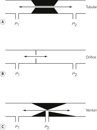
In the case of the tubular flowmeter (Fig. 2.10A), the pressure drop across a tube (or set of tubes) in the stream is measured. Provided the tube is long enough, this causes even turbulent flow to become laminar. As a result, the pressure drop P across the tube is proportional to the volumetric flow rate F, and the constant of proportionality is the resistance R:

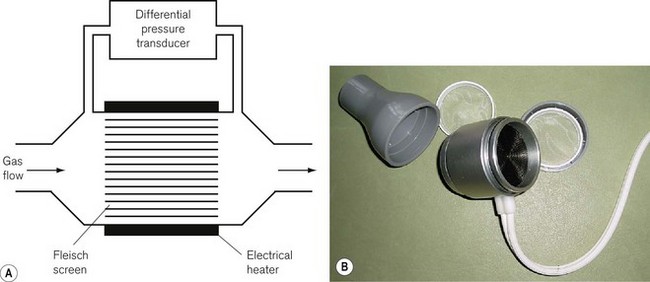
Resistance is inversely proportional to the area of the tube and proportional to its length. Since tube length is usually limited by practical considerations and the need to make the flow in the tube laminar, a reduction in resistance requires an increase in cross-sectional area, which in turn decreases pressure drop and requires that the pressure transducer used is more sensitive. The Fleisch pneumotachograph, is an example of a tubular flowmeter (Fig. 2.11) designed to have a very low resistance to respiratory flows and a very fast response rate. Its construction maximizes the pressure drop, ensures laminar flow measurement conditions with small-bore metal tubes, whilst minimizing the resistance by using a large number of short tubes. To prevent expiratory gas condensing in these tubes they are heated. However, a very sensitive and stable pressure transducer is required to make the respiratory flow measurements.
The operating principle of the orifice flowmeter is the resistance produced by a simple hole (Fig. 2.10B) that has been placed in a plate in the flow stream within the flowmeter. The orifice causes the flow downstream of itself to be turbulent whether the upstream flow is turbulent or not. The pressure drop achieved is thus proportional to the square of the volumetric flow rate, which makes calibrating an orifice flowmeter difficult, even over a limited range of flow rates. However, orifice flowmeters are cheap to make. Since the flow associated with the orifice flowmeter is essentially turbulent it seems an unlikely candidate for a transducer for respiratory reciprocating flows. However, wire screen respiratory flow heads, which effectively use multiple orifices in a similar way to the multiple tubes of the Fleisch pneumotachograph, have fast responses and low resistances to respiratory flows. The wire mesh in these flowmeters can be heated as in the Fleisch pneumotachograph to prevent condensation effecting the measurements.
The final type of differential pressure flowmeter is the Venturi flowmeter (Fig. 2.10C). In this type, the gas is forced through a smoothly narrowed portion of tube. The differential pressure is measured between points upstream of the Venturi and its ‘throat’ (narrowest point). Since the gas is compressed by the restriction it has to accelerate as it passes through the throat. This decreases the pressure in the throat relative to the upstream pressure. Pressure difference is approximately proportional to the square of the flow rate. Venturi flowmeters can be made very accurately but are expensive and are unsuitable for reciprocating respiratory flows.
Variable-area constant differential pressure flowmeters
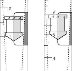
During gas flow, an orifice is created by the annulus between the bobbin and the tube. At any given flow within the operating range of the rotameter, the bobbin will find a level at which the differential pressure created by this annulus results in a force upwards equal to the force of gravity downwards on the bobbin. As shown in Figure 2.12 for a given bobbin and tube design, this equilibrium point will occur at a certain point in the tube for a flow of, say 1.71 min−1. If the flow is then increased to 61 min−1, the bobbin will rise until the annulus is sufficiently large for equilibrium to be re-established. At low flow rates, flow becomes a function of viscosity because the comparatively longer and narrower annulus behaves like a tube. With higher flow rates, the annulus is shorter and wider and behaves like an orifice and is therefore density-dependent. Thus rotameters are only calibrated for a particular dry gas. The weight of the bobbin decides the pressure of operation of the rotameter and is thus constant.
The scale on a rotameter need not be linear if a non-linear taper is used. Figure 2.13 shows a rotameter flow tube with a shallow taper for increased sensitivity at low flows, then a deeper taper for higher flow rates to allow a greater range. An alternative arrangement, allowing improved accuracy, is the use of double flowmeter tubes in series (cascade flowmeters), where the first much narrower tube (and lighter bobbin) has a more gentle taper to allow an expanded scale at low flows (typically reading from 0.25 1 min−1 to 1.0 1 min−1).
The accuracy of the rotameter is dependent on the bobbin being consistently in the centre of the tube. Variation away from the centre can lead to a change in effective annulus area or changes in flow pattern around the bobbin, affecting the consistency of the differential pressure generated. Thus rotameter accuracy is dependent on the tube being vertical. Most bobbins used in rotameters in anaesthetic equipment are also spin stabilized to keep them in the centre of the tube. This is done by cutting angled slots in the top flange of the bobbin (Fig. 2.12) to act as windmill vanes. A further design feature is to have a bobbin with a low centre of gravity so that it is more stable in the gas flow.
Constant temperature hot-wire anemometry
Until relatively recently, the only type of fresh gas supply flowmeter on the anaesthetic machine would have been the rotameter. However, the desire to integrate the functions of the anaesthetic machine with both patient monitoring and ventilator control, in order to create a single integrated anaesthesia workstation, has produced the need to measure gas flows in ways that can be linked to electrical outputs. Differential pressure flowmeters, when combined with solid-state pressure transducers, can produce an electrical output of fresh gas flow and/or respiratory flows in ventilators. An alternative is the hot-wire anemometer (see below), which can now be used more freely than in the past as flammable anaesthetic agents have been taken out of service.
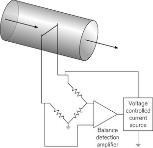
In constant temperature hot-wire anemometry, the wire forms part of a Wheatstone bridge arrangement (Fig. 2.14), which measures the instantaneous resistance of the wire. The resistance will increase as cooling occurs. The output from the Wheatstone bridge is fed to an electronic amplifier, the output from which is used to control the current going to the hot-wire to keep it at a constant temperature/resistance. Thus, the output from the amplifier becomes a measurement of the heat transfer from the wire and hence the gas velocity.
Hot-wire anemometers (see Fig. 10.7) are very sensitive and have very fast response times. As well as being used as sensors of fresh gas flow, they can also be used as sensors of respiratory gas flows. However, since the heat transfer from the wire is dependent on the physical properties of the gas and hence its chemical composition, some care in calibrating the anemometer for changes in inspiratory/expiratory gas composition and humidity is required.
Mechanical flowmeters
The Wright’s respirometer
The Wright’s respirometer (Fig. 2.15A) is an inferential mechanical flowmeter, or rather integrated volume meter. It is inferential in that the turbine it uses does not rely on sensing the entire flow stream but allows some of the flow to leak past the turbine vane. Its principle is shown in Figure 2.15B.
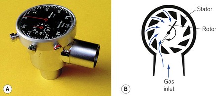
Gas flow to be measured is deflected through a tangentially slotted stator that directs the flow onto a turbine, giving the gas a circular motion (Fig. 2.15B). The turbine is of low mass and the gas flow imparts rotation, by giving up some of its momentum. At equilibrium, the rate of rotation of the turbine is proportional to the volume flow rate. Effectively, one rotation of the turbine is equivalent to the passage of a given volume of gas through the respirometer. Thus, it can be thought of as a volume integrator rather than a true flowmeter. In the original form, which is still on sale, the movement of the turbine is connected to a watch dial-like mechanism via a gearing mechanism and is calibrated in litres.
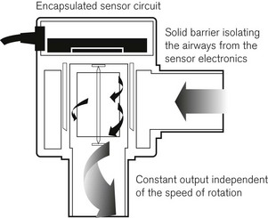
To reduce inertia, the mechanical linkage has been replaced with a magnetic coupling of the turbine (Fig. 2.16) to an electronic scale, where a Hall effect transducer (see below) is used to count the number of rotations of the turbine. Hall effect transducers are semiconductor detectors that respond to very small changes in magnetic field.
The axial turbine flowmeter
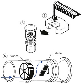
This design of flowmeter has been used in several guises, particularly in ventilators, over a number of years as a respiratory volume monitor. An example is illustrated in Figure 2.17. The advantage of the axial arrangement is that the turbine can be made lower mass and thus has less inertia than a vertical turbine, such as the Wright’s respirometer. It thus suffers from fewer inertia inaccuracies and is accurate over a wider range of flow rates.
Ultrasonic flowmeters
The vortex shedding ultrasonic flow transducer
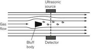
The schematic of a vortex shedding ultrasound flow transducer is shown in Figure 2.18. It consists of a tube in the middle of which is a bluff body that is designed to create vortices of turbulence downstream in its wake. The number of vortices that are shed is linearly proportional to the flow rate. The vortices are detected by their disruption of a narrow ultrasonic beam placed downstream at right-angles to the flow. By putting a second bluff body, facing the opposite way (to the right of the ultrasonic detectors in Fig. 2.18), the transducer can be made bi-directional and can detect reciprocating respiratory flows. Changes in gas composition can affect the rate of vortex shedding but the transducer is relatively insensitive to gas composition change.
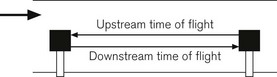
The time-of-flight ultrasonic flow transducer
The schematic of the time-of-flight ultrasonic flow transducer is shown in Figure 2.19. Two ultrasound transmitter/receivers are placed, facing each other, in the middle of the flow. In an alternative design, they are placed facing at each other across the flow stream at an oblique angle. They alternately give ultrasound pulses that the other receives. The time-of-flight of these upstream and downstream pulses is measured. Upstream into the flow, the time-of-flight is increased by the flow velocity, whilst downstream it is reduced by the flow velocity. Given the distance between the transducers, the velocity of flow can be calculated from the length and the difference of the reciprocals of the two times of flight.
Spirometers
Spirometer is a term used to describe a device that measures exhaled tidal volumes and flow state. Many anaesthetists will be familiar from their physiology practicals with the classic Tissot spirometer, where exhaled gasses are collected over water in an inverted bell. In anaesthesia practice, the most common spirometer is probably the Vitalograph single-breath spirometer used for preoperative assessment (Fig. 2.20).
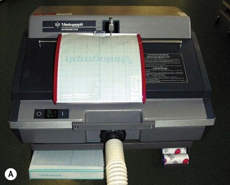
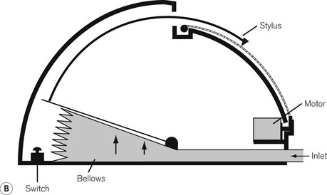
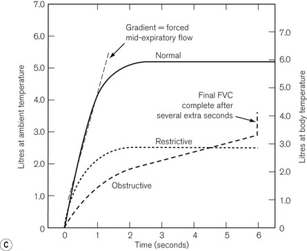
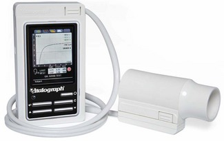
Gradually this classical displaced gas design of spirometer is being replaced with electronic versions that use differential pressure flowmeters to measure exhaled flow. A microprocessor is then used to integrate the obtained flow to give the characteristics graphs of Fig. 2.20C, or to perform direct calculations of forced expiratory volume (FEV), forced expiratory volume in 1 s (FEV1) and vital capacity (VC). This can be done in a hand-held device, such as the Vitalograph In2itive shown in Figure 2.21.
Peak flowmeters
The Mini-Wright peak flowmeter (Fig. 2.22) has long been in use as a low-cost device for the day-to-day measurement of PEF. Several similar designs exist, all of which, in distinction to the Wright’s respirometer (see above) and full size peak flowmeter, are of the variable outlet constant pressure type.
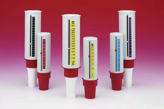
These devices carry their own inaccuracies and were calibrated originally according to the very first type of meter that was available. However, improvements in flow calibration methods, made possible by computerized pump systems, has led to concern over the last 10 years about the inaccuracies of these devices, particularly regarding over-reading in the mid-range of the meters. As a consequence, the European Community issued a new standard, EN 13826, enforced from 2004, which allows only devices meeting these more stringent accuracy requirements to be CE marked. Since 2004, Mini-Wright peak flowmeters have a new EU scale and clinicians need to become familiar with revised ‘normal’ values for PEF in health and disease states.
Hemmings HC, Hopkins PM, eds. Foundations of anesthesia: basic and clinical sciences, 2nd ed, Edinburgh: Elsevier Science, 2004.
Miller MR. Peak expiratory flow meter scale changes: implications for patients and health professionals. Airways J. 2004;2:80–82.
Roberts F. Measurement of volume and flow in gasses. In: Anaesthesia and intensive care medicine. Kidlington, UK: Medicine Publishing Company; 2003.
[/level-membership-for-anesthesiology-category][not-level-membership-for-anesthesiology-category]
Chapter 2 Measurement of pressure and gas flow
Force, pressure and flow
Pressure is force per unit area over which the force acts, i.e.
In any gas or liquid, pressure acts in all directions equally, whereas force acts in a given direction. For example, in a full hypodermic syringe, the liquid can be pressurized by applying a force to the plunger of the syringe. This is applied in the direction of travel of the plunger. However, if there were a leak in the barrel of the syringe, the liquid would squirt out sideways from the leak, as well as from the syringe outlet (Fig. 2.1), due to the pressure created by the force acting in all directions within the barrel of the syringe. The amount of pressure generated depends on the area of cross section of the barrel since it is over this area that the force acts. Thus, the pressure generated in a syringe with a small bore is higher than that generated in a syringe with a large bore for the same force applied to the plunger.
All the individual gas laws, i.e. Boyle’s Law, Charles’s Law and Gay Lussac’s Law, can be summarized in the equation below using the Ideal Gas Law which relates the pressure and volume of a given mass of gas to its temperature:
where P is the pressure of the gas, V its volume, T its temperature, R a constant and n the number of moles of gas present. Measuring the change in the number of moles (n) of a gas in a stream gives a measurement of the number of atoms moving in the flow and is called Molar or Mass Flow.
Atmospheric pressure and partial pressure
The definition of bar given above shows that the air exerts a pressure called atmospheric pressure. Atmospheric pressure is measured using a barometer, the simplest form of which is the Fortin barometer (Fig. 2.2). This consists of a long transparent tube, sealed at one end, which is filled with mercury and inverted with its open end in a bath of mercury exposed to atmospheric pressure. The atmospheric pressure acting on the surface of the mercury in the bath will support a column of mercury of about 760 mm above the surface of the mercury in the bath, leaving a virtual vacuum between the surface of the mercury in the tube and the sealed tube end. The height of column of mercury is measured using a Vernier scale at the top of the tube, which can be adjusted using a knob next to the barometer tube.
Partial pressure
This is Dalton’s Law of Partial Pressures and shows that each gas exerts its own partial pressure independent of its companions. For example, if air is 20% oxygen and 80% nitrogen, then for an atmospheric pressure of 760 mmHg, the partial pressure of oxygen will be 152 mmHg and the partial pressure of nitrogen will be 608 mmHg. However, as Figure 2.3 shows, barometric pressure falls with altitude. Thus, when treating a patient at high altitude, a larger percentage of oxygen is required to supply the same partial pressure of oxygen. It is this partial pressure, not percentage of gas, which is clinically most important. The relationship between altitude and the partial pressure of the components of atmospheric air is shown in Figure 2.4.
Absolute, differential and gauge pressures
Differential pressure measurement is used where the difference in pressure between two points is required. The simplest differential pressure measurement system is the manometer, as shown in Figure 2.5. This takes the form of a U-shaped tube, partially filled with liquid such as water. Gas at pressure P is applied to end A, with end B open to the atmosphere (so having atmospheric pressure applied to it). The pressure at A causes water to be pushed to the other limb of the U so that the level in the right-hand limb moves to point b above where it was before the pressure was applied, and the water in the left-hand limb is depressed below its original level. If both move by a distance of 5 cm then the difference in water level created is 10 cm, indicating a pressure difference between A and B of 10 cmH2O. Since the end B is open to atmosphere, the pressure at A can be thought of as being above atmospheric and is referred to as gauge pressure and is sometimes denoted by placing a ‘g’ after the pressure unit, e.g 10 cmH2O g. If the ends A and B are at different points within a closed system, such as between the pleural cavity and the alveoli, then the pressure measured is a true differential pressure.
Methods of measuring pressure
Mechanical methods
Bourdon gauge
The Bourdon gauge (Fig. 2.6) is robust, inexpensive and can withstand high pressures. It consists of a curved flattened tube, elliptical in section. When pressure is applied, the tube expands and in doing so attempts to straighten out. Levers, gears or a rack and pinion mechanism translate this movement to a dial pointer. The inlet has a constriction within it to protect the gauge from sudden increases in applied pressure. This gauge is normally used in anaesthesia to indicate cylinder and pipeline pressures. In this application, the pressures measured are much greater than atmospheric pressure. As the response to the applied pressure is determined by the mechanical properties of the Bourdon gauge tube, it effectively measures absolute pressure.
Aneroid gauge
The mechanical principles of an aneroid gauge are shown in Fig. 2.7. It measures absolute pressure and, as with the Bourdon gauge, the movement generated by application of pressure to a chamber is translated into movement of a dial by a mechanical linkage. The amount of movement generated is controlled by the compliance of the aneroid chamber so that the more rigid the chamber the higher the pressure that the gauge will indicate. The sensitivity of the gauge can be controlled by the gearing ratio of the rack and pinion. Where encountered in anaesthetic devices, aneroid gauges are relatively delicate and sensitive but able to indicate low pressures. They may be used to measure airway pressure or blood pressure. If the chamber is sealed and evacuated, the gauge becomes the familiar aneroid barometer. Electronic sensors of pressure have largely superseded the aneroid gauge.
Electronic methods
Solid-state electronic pressure transducers
Electronic pressure gauges (transducers) are now the commonest method for the measurement of pressure and (in modified forms) force, in anaesthetic machines and devices such as blood pressure machines or infusion pumps. They can be used for both absolute measurements and differential measurement, depending on how they are housed and mounted. A typical solid-state electronic pressure transducer is shown in Fig. 2.8.
[/not-level-membership-for-anesthesiology-category]
