Masks and oxygen delivery devices
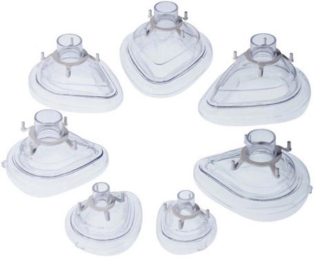
Face masks and angle pieces
Components
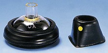
1. The body of the mask which rests on an air-filled cuff (Fig. 6.1). Some paediatric designs do not have a cuff, e.g. Rendell–Baker (Fig. 6.2).
2. The proximal end of the mask has a 22-mm inlet connection to the angle piece.
3. Some designs have clamps for a harness to be attached.
4. The angle piece has a 90° bend with a 22-mm end to fit into a catheter mount or a breathing system.
Mechanism of action
1. They are made of transparent plastic. Previously, masks made of silicon rubber were used. The transparent plastic allows the detection of vomitus or secretions. It is also more acceptable to the patient during inhalational induction. Some masks are ‘flavoured’, e.g. strawberry flavour.
2. The cuff helps to ensure a snug fit over the face covering the mouth and nose. It also helps to minimize the mask’s pressure on the face. Cuffs can be either air-filled or made from a soft material.
3. The design of the interior of the mask determines the size of its contribution to apparatus dead space. The dead space may increase by up to 200 mL in adults. Paediatric masks are designed to reduce the dead space as much as possible.
Problems in practice and safety features
1. Excessive pressure by the mask may cause injury to the branches of the trigeminal or facial nerves.
2. Sometimes it is difficult to achieve an air-tight seal over the face. Edentulous patients and those with nasogastric tubes pose particular problems.
3. Imprecise application of the mask on the face can cause trauma to the eyes.
Nasal masks (inhalers)
1. These masks are used during dental chair anaesthesia.
2. An example is the Goldman inhaler (Fig. 6.3) which has an inflatable cuff to fit the face and an adjustable pressure limiting (APL) valve at the proximal end. The mask is connected to tubing which delivers the fresh gas flow.
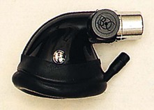
Fig. 6.3 The Goldman nasal inhaler.
3. Other designs have an inlet for delivering the inspired fresh gas flow and an outlet connected to tubing with a unidirectional valve for expired gases.
Catheter mount
This is the flexible link between the breathing system tubing and the tracheal tube, face mask, supraglottic airway device or tracheostomy tube (Fig. 6.4). The length of the catheter mount varies from 45 to 170 mm.
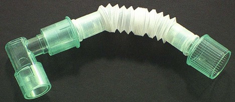
Fig. 6.4 Catheter mount.
Components
1. A corrugated disposable plastic tubing. Some catheter mounts have a concertina design allowing their length to be adjusted.
2. The distal end is connected to either a 15-mm standard tracheal tube connector, usually in the shape of an angle piece, or a 22-mm mask fitting.
3. The proximal end has a 22-mm connector for attachment to the breathing system.
4. Some designs have a condenser humidifier built into them.
Mechanism of action
1. The mount minimizes the transmission of accidental movements of the breathing system to the tracheal tube. Repeated movements of the tracheal tube can cause injury to the tracheal mucosa.
2. Some designs allow for suction or the introduction of a fibreoptic bronchoscope. This is done via a special port.
Problems in practice and safety features
1. The catheter mount contributes to the apparatus dead space. This is of particular importance in paediatric anaesthesia. The concertina design allows adjustment of the dead space from 25 to 60 mL.
2. Foreign bodies can lodge inside the catheter mount causing an unnoticed blockage of the breathing system. To minimize this risk, the catheter mount should remain wrapped in its sterile packaging until needed.
Oxygen delivery devices
Currently, a variety of delivery devices are used. These devices differ in their ability to deliver a set fractional inspired oxygen concentration (FiO2). The delivery devices can be divided into variable and fixed performance devices. The former devices deliver a fluctuating FiO2 whereas the latter devices deliver a more constant and predictable FiO2 (Table 6.1). The FiO2 delivered to the patient is dependent on device- and patient-related factors. The FiO2 delivered can be calculated by measuring the end-tidal oxygen fraction in the nasopharynx using oxygraphy.
Variable performance masks (medium concentration; MC)
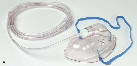
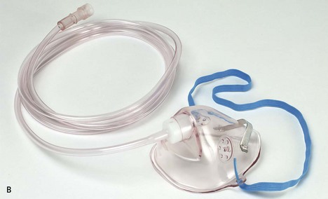
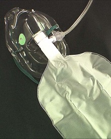
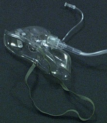
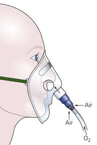
These masks are used to deliver oxygen-enriched air to the patient (Fig. 6.5). They are also called low-flow delivery devices. They are widely used in the hospital because of greater patient comfort, low cost, simplicity and the ability to manipulate the FiO2 without changing the appliance. Their performance varies between patients and from breath to breath within the same patient. These systems have a limited reservoir capacity, so in order to function appropriately, the patient must inhale some ambient air to meet the inspiratory demands. The FiO2 is determined by the oxygen flow rate, the size of the oxygen reservoir and the respiratory pattern (Table 6.2).
Table 6.2
Factors that affect the delivered FiO2 in the variable performance masks
| High FiO2 delivered | Low FiO2 delivered |
| Low peak inspiratory flow rate | High peak inspiratory flow rate |
| Slow respiratory rate | Fast respiratory rate |
| High fresh oxygen flow rate | Low fresh oxygen flow rate |
| Tightly fitting face mask | Less tightly fitting face mask |
Mechanism of action
1. Ambient air is entrained through the holes on both sides of the mask. The holes also allow exhaled gases to be vented out.
2. During the expiratory pause, the fresh oxygen supplied helps in venting the exhaled gases through the side holes. The body of the mask (acting as a reservoir) is filled with fresh oxygen supply and is available for the start of the next inspiration.
3. The final concentration of inspired oxygen depends on:
a) the oxygen supply flow rate
b) the pattern of ventilation. If there is a pause between expiration and inspiration, the mask fills with oxygen and a high concentration is available at the start of inspiration
c) the patient’s inspiratory flow rate. During inspiration, oxygen is diluted by the air drawn in through the holes when the inspiratory flow rate exceeds the flow of oxygen supply. During normal tidal ventilation, the peak inspiratory flow rate is 20–30 L/min, which is higher than the oxygen supplied to the patient and the oxygen that is contained in the body of the mask, so some ambient air is inhaled to meet the demands thus diluting the fresh oxygen supply. The peak inspiratory flow rate increases further during deep inspiration and during hyperventilation.
4. If there is no expiratory pause, alveolar gases may be rebreathed from the mask at the start of inspiration.
5. The rebreathing of carbon dioxide from the body of the mask (apparatus dead space of about 100 mL) is usually of little clinical significance in adults but may be a problem in some patients who are not able to compensate by increasing their alveolar ventilation. Carbon dioxide elimination can be improved by increasing the fresh oxygen flow and is inversely related to the minute ventilation. The rebreathing is also increased when the mask body is large and when the resistance to flow from the side holes is high (when the mask is a good fit). The patients may experience a sense of warmth and humidity, indicating significant rebreathing.
6. A typical example of 4 L/min of oxygen flow delivers an FiO2 of about 0.35–0.4 providing there is a normal respiratory pattern.
7. Adding a 600–800 mL bag to the mask will act as an extra reservoir (Fig. 6.6). Such masks are known as ‘partial rebreathing masks’. The inspired oxygen is derived from the continuous fresh oxygen supply, oxygen present in the reservoir (a mixture of the fresh oxygen and exhaled oxygen) and ambient air. Higher variable FiO2 can be achieved with such masks. A one-way valve is fitted between mask and reservoir to prevent rebreathing.
8. Some designs have an extra port attached to the body of the mask allowing it to be connected to a side-stream CO2 monitor (Fig. 6.7). This allows it to sample the exhaled CO2 so monitoring the patient’s respiration during sedation.
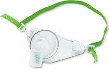
9. Similar masks can be used in patients with tracheostomy (Fig. 6.8). As with the face mask, similar factors will affect its performance. Care must be taken to humidify the inspired dry oxygen as the gases delivered bypass the nose and its humidification.
Nasal cannulae
Nasal cannulae are ideal for patients on long-term oxygen therapy (Fig. 6.9). A flow rate of 2–4 L/min delivers an FiO2 of 0.28–0.36 respectively. Higher flow rates are uncomfortable.
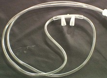
Fig. 6.9 Oxygen nasal cannula.
Mechanism of action
1. There is entrainment of ambient air through the nostrils. The nasopharynx acts as a reservoir.
2. The FiO2 achieved is proportional to:
3. Mouth breathing causes inspiratory air flow. This produces a Venturi effect in the posterior pharynx entraining oxygen from the nose.
4. There is increased patient compliance with nasal cannulae compared to facial oxygen masks. The patient is able to speak, eat and drink.
Nasal catheters
Nasal catheters comprise a single lumen catheter, which is lodged into the anterior naris (nostril) by a foam collar (Fig. 6.10). Oxygen flows of 2–3 L/min can be used. The catheter can be secured to the patient’s face by using tape. It should not be used when a nasal mucosal tear is suspected because of the risk of surgical emphysema.
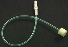
Fig. 6.10 Oxygen nasal catheter.
Open oxygen delivery systems
These are designed to offer the maximum comfort to patients while delivering variable FiO2 concentrations. They fit around the patient’s head like head phones, so making minimal physical contact (Fig. 6.11). Such systems are suitable for both nasal and mouth breathing patients. They may be more suitable for patients on long-term oxygen therapy.
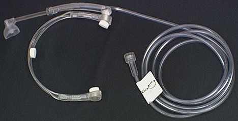
Fig. 6.11 Open oxygen supply system.
Fixed performance devices
Components
1. The plastic body of the mask with holes on both sides.
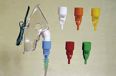
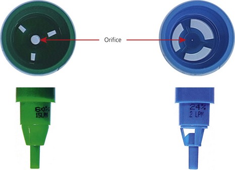
2. The proximal end of the mask consists of a Venturi device. The Venturi devices are colour-coded and marked with the recommended oxygen flow rate to provide the desired oxygen concentration (Figs 6.12 and 6.13).
3. Alternatively, a calibrated variable Venturi device can be used to deliver the desired FiO2.
Mechanism of action
1. The Venturi mask uses the Bernoulli principle, described in 1778, in delivering a predetermined and fixed concentration of oxygen to the patient. The size of the constriction determines the final concentration of oxygen for a given gas flow. This is achieved in spite of the patient’s respiratory pattern by providing a higher gas flow than the peak inspiratory flow rate.
2. As the flow of oxygen passes through the constriction, a negative pressure is created. This causes the ambient air to be entrained and mixed with the oxygen flow (Fig. 6.14). The FiO2 is dependent on the degree of air entrainment. Less entrainment ensures a higher FiO2 is delivered. This can be achieved by using smaller entrainment apertures or bigger ‘windows’ to entrain ambient air. The smaller the orifice is, the greater the negative pressure generated, so the more ambient air entrained, the lower the FiO2. The oxygen concentration can be 0.24, 0.28, 0.31, 0.35, 0.4 or 0.6.
3. The Bernoulli effect can be written as:
where κ is the density, v is the velocity, P is the pressure.
4. The total energy during a fluid (gas or liquid) flow consists of the sum of kinetic and potential energy. The kinetic energy is related to the velocity of the flow whereas the potential energy is related to the pressure. As the flow of fresh oxygen passes through the constricted orifice into the larger chamber, the velocity of the gas increases distal to the orifice causing the kinetic energy to increase. As the total energy is constant, there is a decrease in the potential energy so a negative pressure is created. This causes the ambient air to be entrained and mixed with the oxygen flow. The FiO2 is dependent on the degree of air entrainment. Less entrainment ensures higher FiO2 is delivered and smaller entrainment apertures are one method of achieving this (Fig. 6.8). The devices must be driven by the correct oxygen flow rate, calibrated for the aperture size if a predictable FiO2 is to be achieved.
4. Because of the high fresh gas flow rate, the exhaled gases are rapidly flushed from the mask, via its holes. Therefore there is no rebreathing and no increase in dead space.
5. These masks are recommended when a fixed oxygen concentration is desired in patients whose ventilation is dependent on the hypoxic drive.
6. For example, a 24% oxygen Venturi mask has an air : oxygen entrainment ratio of 25 : 1. This means an oxygen flow of 2 L/min delivers a total flow of 50 L/min, well above the peak inspiratory flow rate.
7. The mask’s side holes are used to vent the exhaled gases only (as above) in comparison to the side holes in the variable performance mask where the side holes are used to entrain inspired air in addition to expel exhaled gases.
8. The Venturi face masks are designed for both adult and paediatric use (Fig. 6.14).
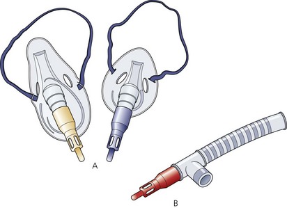
9. The Venturi attachments, with a reservoir tubing, can be attached to a tracheal tube or a supraglottic airway device as part of a T-piece breathing system (Fig. 6.15). This arrangement is usually used in recovery wards to deliver oxygen-enriched air to patents.
Problems in practice and safety features
1. These masks are recommended when a fixed oxygen concentration is desired in patients whose ventilation is dependent on their hypoxic drive, such as those with chronic obstructive pulmonary disease. However, caution should be exercised as it has been shown that the average FiO2 delivered in such masks is up to 5% above the expected value.
2. The Venturi mask with its Venturi device and the oxygen delivery tubing is often not well tolerated by patients because it is noisy and bulky.
Agusti A.G., Carrera M., Barbe F., et al. Oxygen therapy during exacerbations of chronic obstructive pulmonary disease. European Respiratory Journal. 1999;14:934–939.
British Thoracic Society. Online. Available at http://www.brit-thoracic.org.uk.
Khakhar M., Heah T., Al-Shaikh B. Oxygen delivery systems for the spontaneously breathing patient. CPD Anaesthesia. 2002;4(1):27–30.
MHRA. Medical device alert: oxygen masks manufactured by Lifecare Hospital Supplies Ltd (MDA/2011/015). Online. Available at http://www.mhra.gov.uk/Publications/Safetywarnings/MedicalDeviceAlerts/CON108738, 2011.
Stausholm K., Rosenberg-Adamsen S., Skriver M., et al. Comparison of three devices for oxygen administration in the late postoperative period. British Journal of Anaesthesia. 1995;74(5):607–609.
Waldau T., Larsen V.H., Bonde J. Evaluation of five oxygen delivery devices in spontaneously breathing subjects by oxygraphy. Anaesthesia. 1998;53:256–263.
In the following lists, which of the statements (a) to (e) are true?
1. Concerning the Venturi mask:
a) Gas flow produced should be more than 20 L/min.
b) Reducing the flow of oxygen from 12 to 8 L/min results in a reduction in oxygen concentration.
c) With a constant oxygen supply flow, widening the orifice in the Venturi device increases the oxygen concentration delivered to the patient.
2. High-air-flow oxygen enrichment face masks:
a) Use the Venturi principle to deliver a fixed O2 concentration to the patient.
b) The size of the constriction of the Venturi has no effect on the final O2 concentration delivered to the patient.
c) The holes on the side of the mask are used to entrain ambient air.
d) The gas flow delivered to the patient is more than the peak inspiratory flow rate.
3. Face masks used during anaesthesia:
a) The rubber mask is covered by carbon particles which act as an anti-static measure.
b) Masks have no effect on the apparatus dead space.
c) The mask’s cuff has to be checked and inflated before use.
4. Concerning the oxygen nasal cannula:
a) Is a fixed performance device.
b) Is a variable performance device.
c) There is a Venturi effect in the posterior pharynx.
5. Variable performance masks:
a) During slow and deep breathing, a higher FiO2 can be achieved.
b) Ambient air is not entrained into the mask.
c) Alveolar gas rebreathing is not possible.
d) Normal inspiratory peak flow rate is 20–30 L/min for an adult.
6. Regarding variable performance devices:
a) They can offer greater patient compliance.
b) They can deliver an FiO2 that can vary from breath to breath in the same patient.
c) The size of the medium concentration oxygen face mask has no effect on rebreathing and CO2 elimination.
d) Capnography can be used to measure the FiO2 delivered to the patient.
e) With a variable performance mask, the FiO2 is higher when the face mask is a tight fit.
1. Concerning the Venturi mask:
a) True. The Venturi mask is a fixed performance device. In order to achieve this, the flow delivered to the patient should be more than the peak inspiratory flow rate. A flow of more than 20 L/min is adequate.
b) True. It is the flow rate of oxygen through the orifice that determines the final FiO2 the patient receives. With a constant orifice, the amount of air entrained remains constant. So by reducing the oxygen flow rate from 12 to 8 L/min, there will be less oxygen in the final mixture.
c) True. The wider the orifice, the less the drop in pressure across the orifice and the less the entrainment of the ambient air, hence the less the dilution of the O2, resulting in an increase in oxygen concentration delivered to the patient. The opposite is also correct.
d) False. There is no rebreathing in the mask because of the high fresh gas flow rates causing the exhaled gases to be flushed from the mask through the side holes.
e) True. The Venturi mask is a fixed performance device that delivers a constant concentration of oxygen in spite of the patient’s respiratory pattern, by providing a higher gas flow than the peak inspiratory flow rate.
2. High-air-flow oxygen enrichment face masks:
a) True. Laminar flow through a constriction causes a decrease in pressure at the constriction. This leads to entrainment of ambient air leading to mixture of fixed oxygen concentration.
b) False. It is the size of the orifice that determines the degree of decrease in pressure at the constriction. This determines the amount of ambient air being entrained, hence the final concentration of oxygen.
c) False. In such a mask, the holes are used to expel the exhaled gases. There is no entrainment of ambient air in such a mask because of the high gas flows. The holes in a variable performance mask are used to entrain ambient air.
d) True. The gas flow generated is higher than the peak inspiratory flow rate. This allows the delivery of a fixed oxygen concentration to the patient regardless of the inspiratory flow rate. It also prevents rebreathing.
e) False. There is no rebreathing because of the high flows delivered to the patient. The exhaled gases are expelled through the holes in the mask.
3. Face masks used during anaesthesia:
a) True. Carbon particles prevent the build up of static electricity. The rubber face masks and the rubber tubings used in anaesthesia are covered with carbon. With modern anaesthetic practice where no flammable drugs are used, its significance has all but disappeared.
b) False. Face masks can have a significant effect on the apparatus dead space if the wrong size is chosen. In an adult, the dead space can increase by about 200 mL. It is of more importance in paediatric practice.
c) True. The cuff of the face mask is designed to ensure a snug fit over the patient’s face and also to minimize the mask’s pressure on the face. Ensuring that the cuff is inflated before use is therefore important.
d) True. Nasal inhalers are nasal masks used during dental anaesthesia allowing good surgical access to the mouth. The Goldman nasal inhaler is an example.
e) False. The face masks have a 22-mm end to fit the angle piece or catheter mount.
4. Concerning the oxygen nasal cannula:
a) False. It is not a fixed performance device. The final FiO2 depends on the flow rate of oxygen, tidal volume, inspiratory flow, respiratory rate and the volume of the nasopharynx.
c) True. During mouth breathing, the inspiratory air flow produces a Venturi effect in the posterior pharynx entraining oxygen from the nose.
d) False. It is uncomfortable for the patient to have higher flows than 1–4 L/min.
e) True. Patients tolerate the nasal cannula for much longer periods than a face mask. Patients are capable of eating, drinking and speaking despite the cannula.
5. Variable performance masks:
a) True. This allows fresh gas flow (FGF) during the expiratory pause to fill the mask ready for the following inspiration. In tachypnoea (fast and shallow breathing), the opposite occurs where there is not enough time for the FGF to fill the mask.
b) False. The maximum inspiratory flow rate is much higher than the FGF, so ambient air is entrained into the mask through the side holes.
c) False. During tachypnoea, there is not enough time for the FGF to fill the mask and expel the exhaled gases. This leads to rebreathing of the exhaled gases.
e) False. As their performance is variable, the FiO2 the patient is getting is uncertain. Patients who are dependent on their hypoxic drive require a fixed performance mask.
6. Regarding variable performance devices:
a) True. These devices are better tolerated by patients because they are more comfortable. They also offer simplicity, low cost and the ability to manipulate the FiO2 without changing the appliance.
b) True. The FiO2 delivered can vary from one breath to another in the same patient. This is because of changes in the inspiratory flow rate and respiratory pattern. These lead to changes in the amount of air entrained so altering the FiO2.
c) False. Rebreathing is increased when the mask body is large. In addition, the high inspiratory resistance of the side holes increases the rebreathing. CO2 elimination can be improved by increasing the fresh oxygen flow and is inversely related to the minute ventilation.
d) False. Oxygraphy can be used to measure the FiO2 by measuring the end-tidal oxygen fraction in the nasopharynx.
e) True. The tighter the fit of the face mask, the higher the FiO2. Low peak inspiratory flow rate, slow respiratory rate and a higher oxygen flow rate can also increase the FiO2.
7. Concerning fixed performance devices:
a) True. Anaesthetic breathing systems are fixed performance devices. The reservoir bag acts to deliver an FGF that is greater than the patient’s peak inspiratory flow rate.
b) False. The potential energy is related to the pressure, whereas the kinetic energy is related to the velocity of the flow. As the flow of fresh oxygen supply passes through the constricted orifice into the larger chamber, the velocity of the gas increases distal to the orifice causing the kinetic energy to increase. As the total energy is constant, there is a decrease in the potential energy so a negative pressure is created. This causes the ambient air to be entrained and mixed with the oxygen flow.
c) False. The higher the entrainment ratio, the lower the FiO2 delivered. This is because of the ‘dilution’ of the 100% oxygen fresh flow by ambient air.
d) False. Nasal catheters are variable performance devices.
e) False. Venturi masks are not very well tolerated by patients because of the noise and bulkiness of the masks and the attachments.

