Chapter 19 Management of Upper Cervical Spine Tumors
INTRODUCTION
Spinal tumors around the atlantoaxial spine are very rare, and most of them are metastatic. Patients with tumors in this area present with severe mechanical neck pain that is elicited in flexion, extension, and lateral rotation. Pain on lateral rotation distinguishes atlantoaxial tumors from tumors occurring in the subaxial cervical spine. In the subaxial spine, mechanical pain generally is a late manifestation indicating a compression or burst fracture with resultant instability.1 Neurological symptoms resulting from a tumor at C1 and C2 are rare. Patients with C2 nerve root involvement or compression may present with occipital neuralgia. Cranial nerve involvement suggests a tumor extension to the skull base. Myelopathy is rare, given the wide mid-sagittal canal diameter at this spine level. Most cases of spinal cord compression at this level result from pathological fracture subluxations rather than an epidural tumor.
TOTAL SPONDYLECTOMY FOR UPPER CERVICAL TUMORS (TUMOR MASS ON C2–4 LEVELS)
POSTERIOR APPROACH
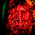
After the airway is maintained with a tracheostomy, the patient is positioned prone with skeletal fixation. A midline skin incision is made, and subperiosteal muscle dissection is accomplished from the external occipital protuberance to the upper thoracic levels to expose the multiple level laminae and facet joints (Fig. 19-1). Complete bilateral laminectomies and facetectomies of C2–4 are performed with wide exposure of the exiting nerve roots.
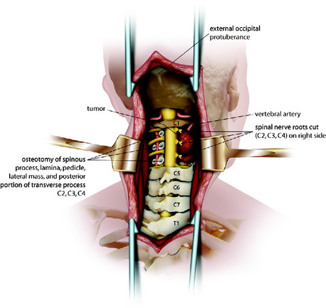
Fig. 19-1 Posterior decompression from C2 to C4.
Modified from Jackson RJ, Gokaslan ZL: Occipitocervicothoracic fixation for spinal instability in patients with neoplastic processes J Neurosurg 1999;91[1 suppl]:81–89.
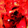
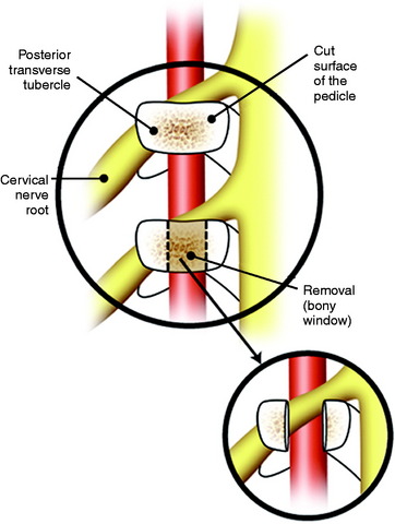
Using a high-speed drill with a diamond burr, the vertebral artery (VA) is freed from C2 to C4 on both sides. When the facetectomy is complete, the cut surface of the pedicle is exposed (Fig. 19-2). The pedicle forms the posteromedial wall of the transverse foramen. Continuous drilling of the pedicle can open the transverse foramen. During drilling, the exiting nerve root on the upper level may be injured. The exiting nerve root is located on the upper portion of the exposed pedicle (see Fig. 19-2). If the VA on the unilateral side is encased within the tumor mass, the cephalad and caudal portions out of the tumor mass are exposed.3 An initial dissection plane is created around the lateral aspect of the tumor.
For the easier dissection, the C2 and C3 nerve roots may be sacrificed without significant functional loss. If necessary, the C4 root also can be included. A Silastic sheet is then placed between the tumor and the ventral dura to protect the neural structures during the subsequent anterior procedure. Occipitocervical fixation is performed using the contoured titanium rods.4
ANTERIOR PROCEDURE—TRANSMANDIBULAR, CIRCUMGLOSSAL, RETROPHARYNGEAL APPROACH
Upper Neck Dissection
A curvilinear incision is begun below the mastoid tip and extended 2 cm inferior and parallel to the lower margin of the mandible inferiorly and medially to the mentum. The incision continues to the vertical incision to the midline of the lower lip. The turning point of the incision lies on the hyoid bone. The lower lip is incised with a zigzag incision. A mucosal incision is made at the alveolar margin under the lower lip. After the skin incision, a vertical incision of platysma is made on the mental symphysis to the superior notch of the thyroid cartilage (Fig. 19-3, A). The platysma can then be transected across its fibers parallel to the direction of the primary incision for the full length of the exposure. Subplatysmal flaps are elevated to expose the upper neck, the submandibular gland, and surrounding tissue.
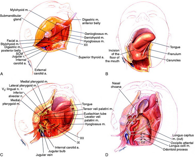
A supraomohyoid neck dissection (usually by an otolaryngologist) provides access to the lingual and hypoglossal nerves as well as the internal carotid artery (ICA), external carotid artery, and internal jugular vein.5 The sternocleidomastoid muscle is retracted laterally to expose the carotid sheath. The digastric muscle is then divided, and the mylohyoid muscle is freed from the hyoid bone and the geniohyoid from the mandible. The hypoglossal nerve should be identified and saved.
Mandibulotomy
A stairstep mandibulotomy is performed between tooth 24 and 25 (lower two mandible molars).6 The mandible is exposed by subperiosteal dissection laterally to the mental foramen. For accurate alignment, the mini-plates should be pre-bent and fitted, and screw holes should be predrilled. Only then is the mandible split with a staircase osteotomy.
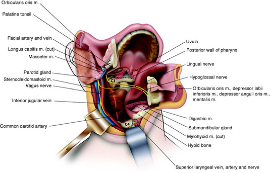
Dissection follows the floor of the mouth posteriorly toward the glossopharyngeal sulcus, which allows the mandible to swing laterally and the tongue medially (Fig. 19-3, B). An incision is made from the midline under the tongue where the mandible has been divided and is continued around the tongue to the tonsillar pillar. The tongue is retracted away from the field as the mandible half is swung out laterally with the cervical myocutaneous flap. The oropharynx and the upper cervical pharyngeal space communicate. The styloid process is palpated and the muscular attachments are separated. The ICA, internal jugular vein, and the 9th, 10th, 11th, and 12th cranial nerves are identified superiorly to the skull base.
As the incision approaches the anterior tonsillar pillar, it splits into two limbs. The upper limb of incision extends to the soft palate. This incision is then carried onto the hard palate approximately 1 cm medial to the alveolar ridge. It then passes anteriorly around to the contralateral hard palate. The lower limb of the incision extends into the hypopharynx, passing lateral to the tonsil and the orifice of the eustachian tube. The levator and tensor veli palatini muscles and the eustachian tube are transected, and a retropharyngeal dissection is used to elevate the pharynx off of the longus colli muscles and expose the clivus and upper cervical spine (Fig. 19-3, C). This pharyngeal flap is elevated and rotated medially. The longus capitis muscle and the prevertebral fascia cover the clivus and upper cervical spine. The posterior pharyngeal wall is incised, and the longus capitis and rectus capitis muscles are retracted (Fig. 19-3, D).
En Bloc Resection
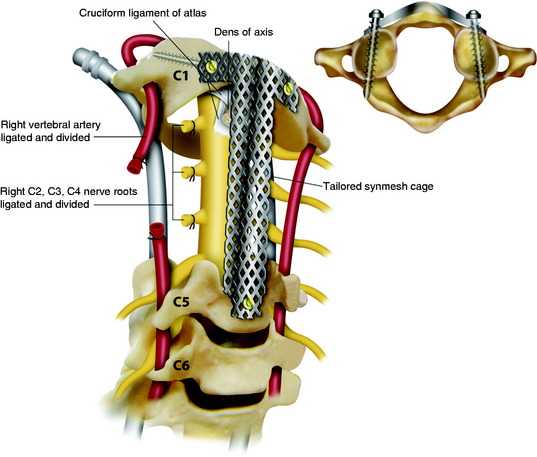
The C4–5 discectomy is performed, the uncovertebral joints are drilled away, and the posterior longitudinal ligament is removed. The soft tissue is freed from the anterior arch of C1. On the intact side, the longus colli and longus capitis muscle insertions are released from C2–4. The transverse processes are drilled away with a diamond burr, completing the circumferential exposure of the VA from C2 to C4. On the tumor-involved side, the longus colli muscle is cut above and below the tumor, and the VA is dissected above C2 and below C4 such that the tumor capsule is not violated. Additional dissection is then performed around the lateral aspect of the tumor mass, medial to the carotid sheath, which communicates with the dissection plane already made in the posterior side. The tumor-involved VA is then ligated and transected both rostral and caudal to the tumor mass, freeing the specimen along its lateral aspect (Fig. 19-4). Finally the high-speed drill is used to cut across the base of the dens, and Kerrison rongeurs are used to resect the ligamentous complex behind the dens.
Anterior Stabilization
A long, titanium mesh cage filled with allograft or autograft is remodeled to reconstruct the spine in an innovative manner. At the rostral and caudal ends, the dorsal aspect of the cage is cut away, allowing it to fit between C1 and C5 as a strut graft. The ventral aspect of the cage is positioned anterior to the arch of C1 and the body of C5, functioning as a plating mechanism. At the rostral end, the mesh is spanned out and attached to the anterior surface of the C1 arch (Figs. 19-5 and 19-6). Two tricortical screws are placed through the anterior part of the cage, through the lateral mass of C1. Caudal screws are inserted to the C5 body with bicortical purchase.
CASE ILLUSTRATION
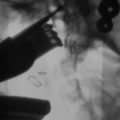
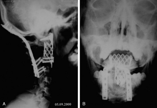
The patient presented with severe neck pain and no history of a malignancy. Subsequently, lymphoma was diagnosed. Preoperative x-rays show that angulation was more than 11 degrees. Intraoperative reduction and stabilization were performed from C1 to C3 using the Apofix cervical sublaminar clamp (Fig. 19-7). The patient was subsequently treated with radiation therapy.
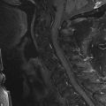
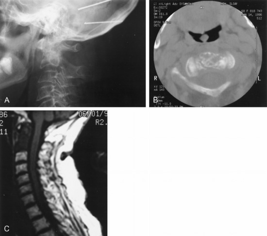
This patient was diagnosed with a C2 metastasis of breast cancer (Fig. 19-8). X-rays and magnetic resonance imaging (MRI) show that the odontoid subluxation is less than 2 mm. The spinal cord is not compressed. The patient responded to external beam radiation therapy in a hard collar and showed significant pain resolution. She was then weaned from the collar 6 weeks after treatment.
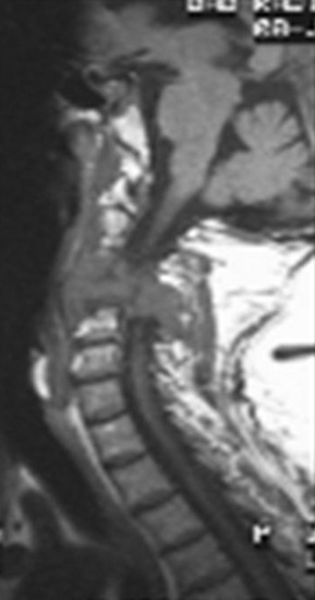
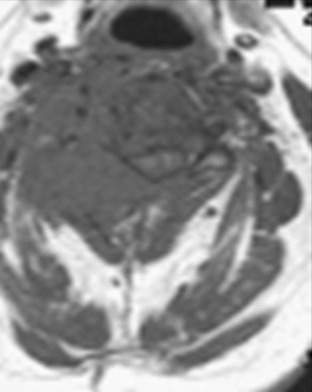
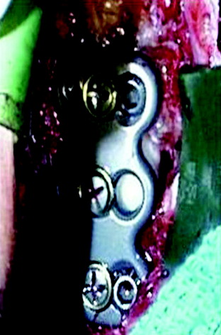
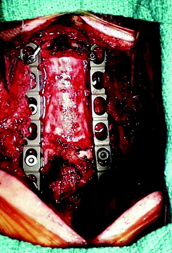
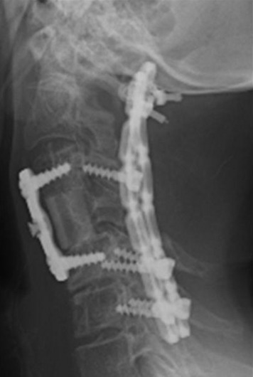
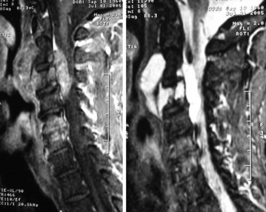
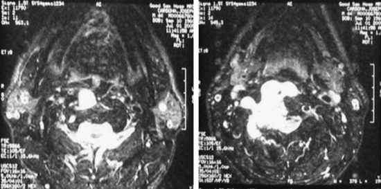
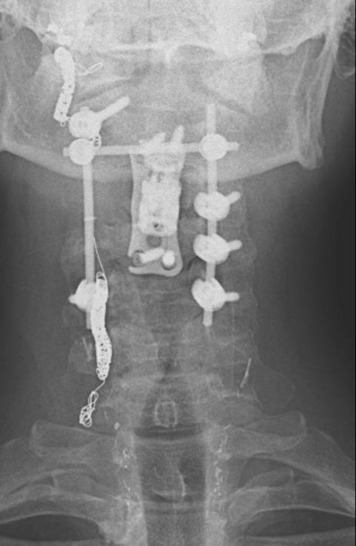
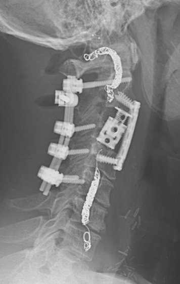
This 34-year-old patient presented with severe neck pain with shoulder pain. The percutaneous biopsy was confirmed as lymphoma. MRI showed the C4 mass that destroyed the vertebral body, extended to the right C3–4 facet joint, and encased the right VA (Figs. 19-9 and 19-10). The operation was performed using the anterior approach, followed by the posterior approach. A C4 corpectomy was performed, and a fibular strut was replaced into the corpectomy site. Anterior plating was added (Fig. 19-11). In the posterior operation, a total laminectomy of C2–4 and right C3–4 facet joint resection were performed. Posterior instrumentation was performed with a lateral mass screw-and-plate system (Fig. 19-12). The screws were inserted into the C5 and C6 levels bilaterally and into the left C3 facet. Wire fixation was supplemented at the C1 level (Fig. 19-13).
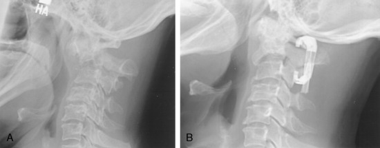
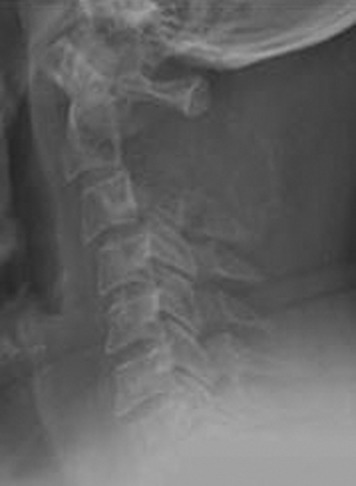
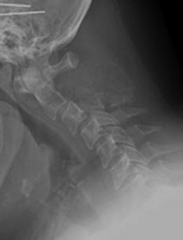
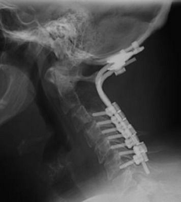
This patient presented with posterior neck pain with occipital pain. Preoperative lateral x-rays showed that the C2 posterior element completely disappeared and that the C3 posterior element was partially eroded (Fig. 19-14). With a dynamic lateral view, anterior column instability was not shown (Fig. 19-15). The operation was performed using the posterior approach only. A C2 total laminectomy and bilateral facetectomy were performed. At the C3 level bilateral laminae were removed but the facets remained. Occipitocervical stabilization was performed with a screw-rod system (Fig. 19-16). The lateral mass screws were inserted at the C3–6 levels.
VERTEBRAL ARTERY MANAGEMENT DURING TUMOR REMOVAL
The management of VAs in cases of cervical spine tumor can be performed in several ways. They may be dissected and mobilized away from the tumor; they may be ligated and resected with the tumor; or in certain cases they may be resected and reconstructed with a venous interposition graft.7 The VA from C6 to C2 (V2 segment) may be reached from an anterolateral approach behind the carotid sheath.8 At C2 and C1 (V3 segment) the artery is approached laterally. In the V2 and V3 segments it is completely surrounded by a continuous periosteal sheath and venous plexus. The key points in VA control are to stay outside the periosteal sheath as long as possible and to obtain adequate VA control proximal and distal to the lesion.
C1–2 LEVEL (V3 SEGMENT)
Position and Skin Incision
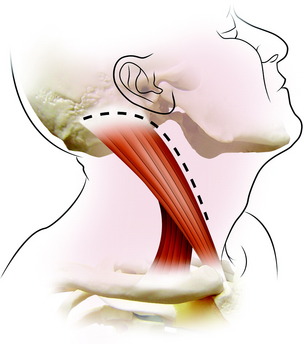
This approach is medial to the sternocleidomastoid (SCM) muscle and lateral to the carotid sheath. The ear lobe is temporarily reflected and sutured to the skin in front of the ear. A hockey stick–shaped incision is made transversely over the proximal SCM muscle, then distally along the anterior border of this muscle and posteriorly curving across the mastoid process (Fig. 19-17). After the skin incision, subcutaneous layer and platysma muscle are divided along the skin incision line.
Muscle Dissection
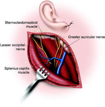
Underneath the platysma muscle the greater auricular nerve is dissected for mobilization. The external jugular vein is seen to overlie the SCM muscle. It can be ligated if necessary. The posterior portion of the parotid gland is shown on the anterior border of the sternocleidomastoid muscle and should be protected. The insertions of the SCM muscle and part of the splenius capitis muscle are divided at the base of the skull (Fig. 19-18). The spinal accessory nerve is identified entering the deep surface of the SCM muscle about 3 or 4 cm below the mastoid tip. The tip of the transverse process of C1 can be identified by palpation 1 cm below and 1 cm in front of the mastoid tip.
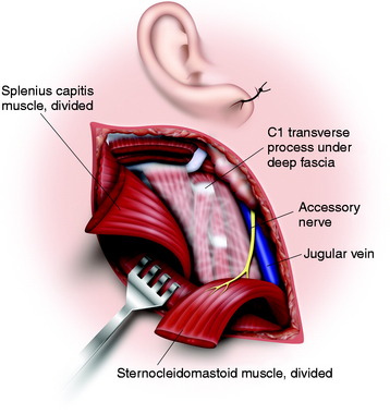
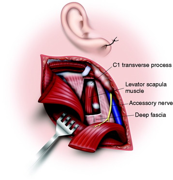
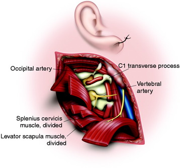
The deep fascia is incised from the tip of the C1 transverse process obliquely downward parallel to the course of the spinal accessory nerve (Fig. 19-19). The thick levator scapulae muscle and the slender splenius cervicis muscles are picked up and divided from the attachment of the C1 transverse process (Fig. 19-20).
Exposure of Vertebral Artery
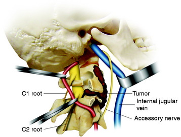
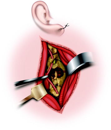
After all the muscles are detached from the transverse processes of C1 and C2, then the accessory nerve, the VA, and the lateral part of C1 and C2 are visualized.9 The internal jugular vein is anterior to the transverse process, and the accessory nerve crosses it here after it emerges from the jugular foramen on the way to the SCM. The VA can be identified between C2 and C1 by following the inferior border of the inferior oblique muscle in the loose adipose tissue (see Fig. 19-20). The ventral ramus of the C2 nerve root crosses lateral to the VA from posterior to anterior. The transverse process of C1 is rongeured away, permitting the artery to be displaced out of C1 and reflected posteriorly, allowing clear access to the tumor in the anterior part of C1 and C2. The artery can be followed down into the C2 transverse foramen after dividing the ventral ramus of the C2 root (Fig. 19-21). The periosteal-venous sheath is opened and reveals significant venous bleeding. To control the bleeding, it is best to coagulate the vein and strip the sheath from the artery. In the V3 segment, the VA is surrounded by a venous plexus, and both the VA and its venous plexus are enclosed in a continuous periosteal sheath. This sheath is continuous with the periosteum of the transverse foramina of C1 and C2, with the deep aponeurosis of the muscles between these foramina, with the posterior atlantooccipital membrane that arches over the VA groove of the atlas, and with foramen magnum dura mater.
Vertebral Artery Transposition
For the transposition, complete control of the VA and cutting of all the branches are required.10 After controlling the two parts of the suboccipital segment on each side of the C1 transverse foramen, the periosteal sheath is followed inside the foramen, splitting the periosteum from the bone. Then the transverse foramen is unroofed, biting its external wall progressively using the Kerrison rongeur (Fig. 19-22). To achieve the transposition, the medial wall must also be resected to provide space in the concavity of the VA loop and allow the VA to be pulled without damaging the periosteal sheath.
BELOW C2 LEVEL (V2 SEGMENT)
Incision
The internal jugular vein is identified medial to the muscle, and the dissection is carried out between the carotid sheath and the SCM, down to the anterior tubercles of the cervical vertebrae.11 When the tumor mass encases the VA, the proximal segment to the mass needs to be controlled. If the intact anterior tubercle below the tumor mass is identified, the muscles are detached from the anterior tubercle (Fig. 19-23). The bone is gently rongeured down to the foramen transversarium. The VA is identified within the venous periosteal sheath. Then the venous sheath is opened and dissected circumferentially around the artery with bipolar coagulation. If only the proximal control is required, the naked portion of the VA should be exposed at the C7 level. Once the artery is exposed from the venous sheath, a rubber vessel loop is passed around it. When proceeding in the cephalad direction, great care should be taken to avoid injuries to nerve roots and phrenic nerve lying on the scalenus anterior muscle.
CASE ILLUSTRATION
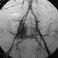
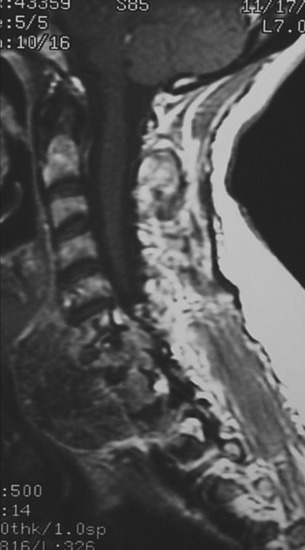
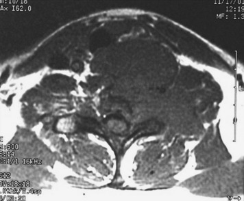
On preoperative MRIs a tumor mass was detected from the C3 body and extended to the anterior direction. The anterior mass invaded into the epidural space from C2 to C4, and the spinal cord was severely compressed (Fig. 19-24). The right VA was encased in the tumor mass at the C3 level (Fig. 19-25). A preoperative angiography was performed to evaluate the patency of the VA. During the angiography a balloon occlusion test was performed. Neurologically, no abnormal finding was detected. The VA was trapped with two balloons to control bleeding.
Via a posterior approach, the right C2–3 and C3–4 facets were removed with the tumor mass, and posterior stabilization was performed. On the right side, a C2 pedicle screw and a C5 lateral mass screw were purchased. On the left side, lateral mass screws were inserted on the C3–5 levels (Figs. 19-26 and 19-27). With a subsequent anterior approach, a C3 corpectomy and epidural mass removal were carried out. A vertebral body replacement cage was inserted into the corpectomy site and supplementary plating was done. On the postoperative x-ray, the embolic material is seen in the right VA.
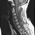
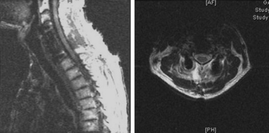
This case illustrates a patient with chordoma. The tumor mass involves the C5 and C6 vertebral bodies. The tumor mass destroyed the C5 and C6 body and encased the right VA and right C5 and C6 nerve roots in the neural foramen. The anteriorly protruding mass extends to the T2 vertebral body level (Fig. 19-28).
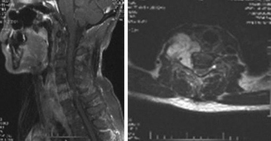
Fig. 19-28 MRI; the tumor mass from C5 and C6 encased the right VA and extended to the intervertebral foramen.
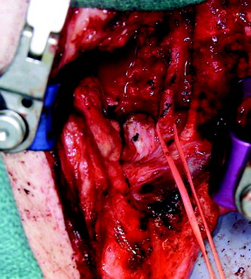
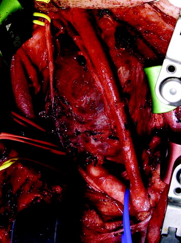
The operation was performed using the anterior approach first. For the complete removal of the ventral mass, manubrial splitting was needed. Anterior decompression was accomplished with a right VA dissection. The VA was skeletalized from the tumor mass (Fig. 19-29). Anterior stabilization was performed from C4 to C7, and posterior supplementary stabilization was performed from C3 to T1 with lateral mass screws (Fig. 19-30).
Another chordoma case is presented here at the C7–T1 level. In this case, the left VA is encased within a tumor mass (Figs. 19-31 and 19-32).
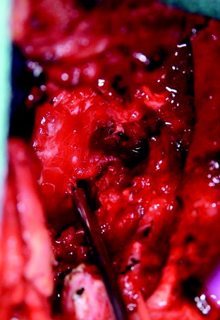
With a transmanubrial approach, the anterior tumor mass was well decompressed. The consistency of the mass was soft and suckable. A partially solid portion was included. Mass removal was not difficult. The left VA was dissected from the tumor mass (Fig. 19-33). During dissection, moderate bleeding was observed. The bleeding was controlled with compression with hemostatic materials. The nerve roots (left C7, C8) were seen through the corpectomy site after the mobilization of the VA (Fig. 19-34).