[level-membership-for-orthopaedics-category]
CHAPTER 53 Linked Elbow Arthroplasty: Rationale, Indications, and Surgical Technique
INTRODUCTION
As noted in Chapter 52 and further described in Chapters 54 through 60, the results of total elbow arthroplasty are improving with increased basic knowledge of elbow mechanics,24 better designs, and greater surgical experience.21 The general principles of the surgical technique and improved designs2,9,14,18,24 and a detailed description of my specific method of inserting the Coonrad-Morrey implant are presented. The results of semiconstrained joint replacement arthroplasty emphasize the Mayo Clinic experience with the modified Coonrad device.
RATIONALE
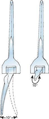
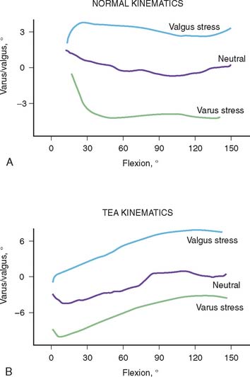
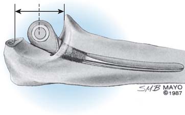
The selection and the rationale for unlinked elbow replacement are described in Chapter 52. The reason for continuing to use a semiconstrained linked implant is simple: the current design works well, is reproducible, and can address a broad spectrum of pathology. The Coonrad-Morrey linked device and similar implants are distinctly different, both conceptually and clinically, from the original, fully constrained articulated devices. In today’s linked prostheses, the one feature in common is that the ulnar component is coupled to the humerus with angular and rotatory laxity of 5 to 10 degrees (Fig. 53-1). The theoretical advantage has been confirmed in the laboratory in which it was demonstrated that the articulation tracks within the limits of its tolerance (Fig. 53-2). This decreases stresses on the bone-cement interface.24 Documentation of improved clinical results attests to the effectiveness of the semiconstrained linked design.2,4,13,14,16,18,21 Of particular note is that the linked implant dramatically broadens the indications for reconstructive surgery of the elbow. Whereas unlinked devices may be very effective for rheumatoid arthritis, the potential for instability limits their use when deformity and osseous and ligamentous deficiency is present. The linked implant may be used with equal effectiveness in patients with rheumatoid arthritis,20 for post-traumatic arthrosis,19 and for revision surgery.18 The enhanced stability supplied by the coupling is provided without transmission of excessive stress to the bone-cement interface with the semiconstrained design.24
CONTRAINDICATIONS
As for any total elbow arthroplasty, the absolute contraindications for a linked arthroplasty are active infection, inadequate soft tissue protection, and the lack of adequate motor muscle power to flex the elbow to ensure proper functioning of the device. Relative contraindications are lack of patient compliance. Primary degenerative joint disease is also a relative contraindication because patients with this disease are usually younger and active, and alternative selections are effective (see Chapter 60). High demand and a dysfunctional hand are also relative contraindications for total elbow arthroplasty.
PRINCIPLES OF SURGICAL TECHNIQUE
SURGICAL INCISION
A straight posterior skin incision is preferred. If a previous incision is present it is employed when possible. If the patient is older than 4 or 5 years of age, it may be repaired if it cannot be incorporated. The incision need not and should not be curved.
THE ULNAR NERVE
Opinions are divided with respect to the management of the ulnar nerve. Some surgeons believe that it should not be exposed,7,9,12,16,27 whereas today most believe that the ulnar nerve should be directly visualized and moved as an integral part of the surgical approach and procedure.4,10,15,23 We favor the latter philosophy.
THE TRICEPS
The fascial tongue exposure of Campbell (Van Gorder) causes a good deal of soft tissue dissection, with a significant amount of dead tissue that provides an environment favorable to infection, which may result in weakness.5,22 Splitting the triceps in the midline is enjoying a resurgence of popularity. In our experience, this tends to cause detachment of the medial insertion. Therefore, I continue to prefer the Mayo technique of reflecting the triceps in continuity with the ulnar periosteum and forearm fascia described by Bryan and Morrey.5 The important point, however, is a meticulous repair (see later).
AXIS OF ROTATION
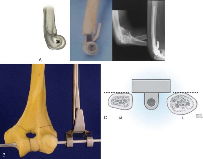
The philosophy of the Coonrad-Morrey device is to use the most reliable landmark to serve as the basis for defining the flexion axis. The landmark selected for this system is the anterior cortex to establish the anterior/posterior position of the axis. The roof of the coronoid fossa is the anatomic reference for depth of insertion, and the plane of the columns define the rotation of the axis of the humeral component (Fig. 53-3).
CEMENTING TECHNIQUE
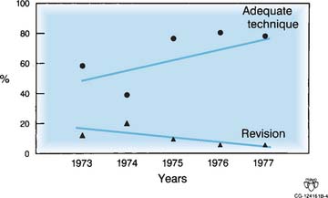
The cement should be introduced down the medullary canal for stemmed implants with an injection system. Generally speaking, injector systems have dramatically improved the radiographic appearance of the bone-cement interface. It was shown in our early experience20,23 and subsequently Faber,8 that the quality of the cementing technique is inversely related to the presence of lucent lines, and, ultimately, to implant loosening (Fig. 53-4).
TRICEPS REATTACHMENT
Triceps reattachment has emerged as a major emphasis for all elbow joint replacement surgery. Whenever the triceps is reflected from its attachment, it must be securely reattached to the olecranon by nonabsorbable sutures placed through bone. The sutures should be tied with the elbow in 90 degrees of flexion, but knots are avoided over the subcutaneous border of the ulna. Because the attachment communicates with the joint and motion will allow the synovial fluid to become interposed between the triceps and the olecranon, an attachment may be compromised. The transverse “cinch” suture applies the tendon to the olecranon. To enhance strength and ensure continuity, we also tend to displace the extensor mechanism slightly medially, if possible, bringing the anconeus slightly over the proximal ulna.
POSTOPERATIVE DRESSING
We have had virtually no incision problems because we have been routinely placing the elbow in full extension with an anterior splint and elevating the arm for approximately 24 hours. We see no advantage to allowing the elbow to assume 90 degrees of flexion immediately after surgery. Because of continued concern for the variable swelling and occasional blistering that may occur after surgery, I no longer use the Steri-Drape, and I avoid Betadine solution if the barrier drape is used. A prospective, randomized study recently revealed statistically measurable decreases in swelling after surgery with the use of a compression Cryocuff (Aircast Co., Coconut Creek, FL).1
THE SEMICONSTRAINED LINKED IMPLANT
Today, in the United States, several semiconstrained elbow replacements are commercially available, including the Coonrad-Morrey (Zimmer, Warsaw, IN), the Latitude (Tornier, Edina, MN), and the Discovery (Biomet, Warsaw, IN). To date, these two implants have not had sufficient use to document outcomes. The GSB III has evolved through the years and has been frequently used in Europe but its use and support is being discontinued (Fig. 53-5). Experience with the GSB III devices is discussed under the appropriate indications in subsequent chapters. Risung25 has also reported favorable outcomes with a rather novel implant designed termed the Norway elbow.
THE COONRAD-MORREY DEVICE
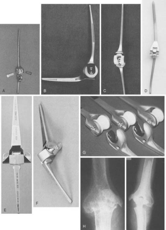
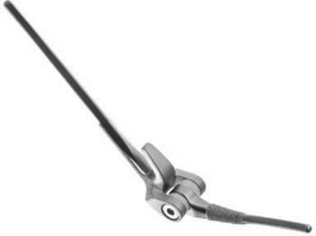
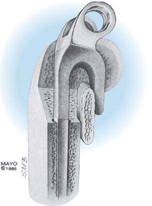
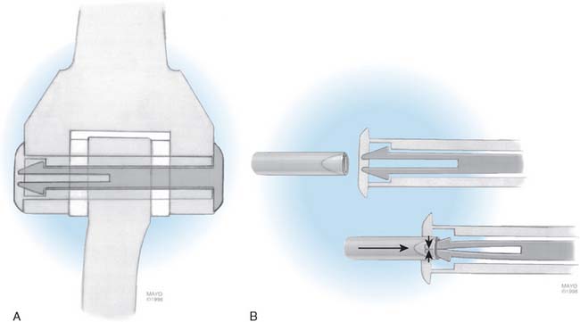
The Mayo modified Coonrad total elbow prosthesis (Coonrad-Morrey) is a semiconstrained device manufactured from Tivanium Ti-6Al-4V alloy. In 1978, the initial design (Coonrad I) Zimmer Company (Warsaw, IN). was modified by the Mayo Clinic to permit 7 to 10 degrees of hinge laxity, or toggle (Coonrad II), which is consistent with the average laxity of the normal elbow joint (Table 53-1). This change accounts for the semiconstrained designation applied to the device. The effect of this design concept is discussed above (see Figs. 53-1 and 53-2). The implant was designed for use with methylmethacrylate and is manufactured in two sizes: a regular and a small size (15-percent reduction). The current limited version was released in 1981. It currently has a basic hinge articulation with a hollow cobalt chrome pin that passes through the ultra-high-molecular weight polyethylene bushings to capture the ulnar component. A second pin is inserted from the opposite side to secure the articulation (Fig. 53-6). The prosthesis is easily disassembled if desired. A flange was incorporated in this version to resist posterior and torsional forces.
| Device | Year | Feature/Modification |
|---|---|---|
| Coonrad | 1971 | Rigid hinge |
| Coonrad II | 1978 | Semiconstrained loose hinge |
| Coonrad-Morrey | 1981 | Flange, surface treatment |
| 1984 | Plasma spray replaced with beads | |
| 1991 | Beads on ulna replaced with polymethyl methacrylate precoat | |
| 1993 | Titanium articular pin replaced by cobalt-chromium pin | |
| 1998 | C ring replaced by pin within a pin |
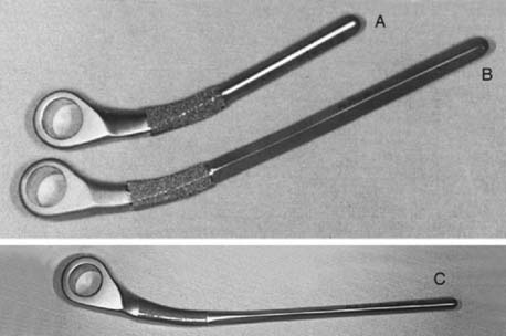
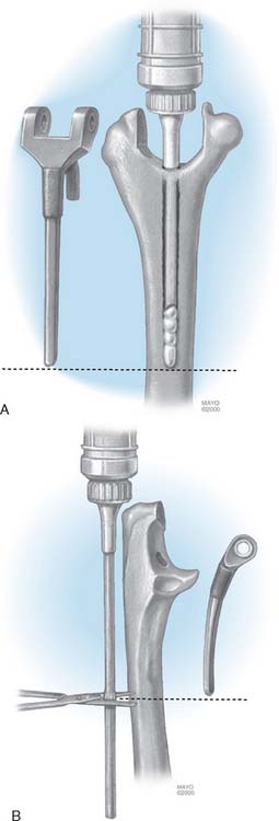
This implant is intended to be used with bone cement for both immediate and long-term fixation. The humeral stem comes in 10-, 15-, and 20-cm stem lengths (Fig. 53-7). The 15-cm stem is most often used in nonrheumatoid patients to ensure adequate mechanical resistance to rotation in the humerus. The 4-inch stem is used when a shoulder involved by rheumatoid arthritis has been or may be replaced with a humeral prosthesis.11,13 The 8-inch stem is used for revision procedures requiring the device to bypass the prior stem tip (see Chapter 66). The ulna implant is made in standard and small dimensions. The small dimension also comes in an extra long size. Finally, for the patient with juvenile rheumatoid arthritis or a very small canal, as is common in those from Asia, a special extra-small implant is available (Fig. 53-8).
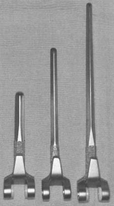
FIGURE 53-7 The humeral components are available in 10-, 15-, and 20-cm lengths and in small and standard sizes.
SURGICAL TECHNIQUE FOR COONRAD-MORREY TOTAL ELBOW ARTHROPLASTY
Author’s Preference
Exposure
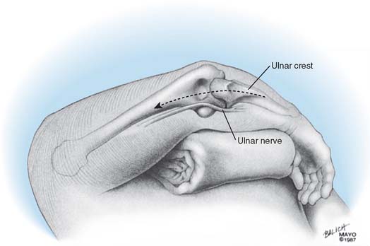
The patient is positioned supine with a sandbag under the scapula, and the arm is draped free with a nonsterile tourniquet and brought across the chest (Fig. 53-9). The Mayo (Bryan-Morrey) approach is used exclusively for this procedure if condyles are present. In the absence of a distal humerus, the triceps attachment to the olecranon is maintained.5 A straight 15-cm incision is centered just lateral to the medial epicondyle and just medial to the tip of the olecranon. The medial aspect of the triceps is identified, and the ulnar nerve is carefully isolated and translocated using ocular magnification and a bipolar cautery. It is gently protected throughout the remainder of the procedure.
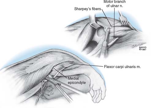
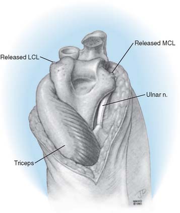
Over the medial aspect of the proximal ulna, the ulnar periosteum is elevated along with the forearm fascia (Fig. 53-10). The posterior capsule is incised. The triceps is elevated from the proximal ulna by transecting Sharpey’s fibers at the site of insertion. The extensor mechanism, including the anconeus, is reflected laterally, allowing complete exposure of the distal humerus, the proximal ulna, and the radial head. The radial and ulnar collateral ligament complexes are released from their attachments in persons with rheumatoid arthritis (Fig. 53-11). Failure to do this may facilitate a fracture of the medial column as the forearm is manipulated. The tip of the olecranon is removed.
Humeral Preparation
The midportion of the trochlea is removed with a rongeur or a saw, depending on the softness of the bone. The medullary canal of the humerus is identified by entering it with a rongeur or a burr at the roof of the olecranon fossa (Fig. 53-12) and entered with a twist reamer. The medial and lateral aspects of the supracondylar columns should be identified and visualized throughout the preparation of the distal humerus to ensure proper alignment and orientation.
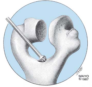
FIGURE 53-12 The medullary canal is identified by perforating the roof of the olecranon fossa with a burr or a rongeur.
(With permission from the Mayo Foundation.)
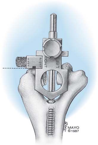
The alignment stem is placed down the canal (Fig. 53-13). The handle is removed, and a cutting block is attached, which allows accurate removal of the appropriate amount of the articular surface of the distal humerus.
The interchangeable side arm of the cutting block is attached laterally to rest on the capitellum and to provide the appropriate depth of cut (Fig. 53-14).
The humerus involved by rheumatoid arthritis is easily prepared with a rasp in such a way as to receive the appropriately sized humeral component. In younger patients and those with post-traumatic conditions, the canal may be tight, or the anterior humeral bow may make preparation more difficult. A burr is effective to remove bone just proximal to the oriface of the olecranon fossa.
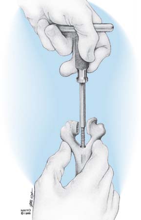
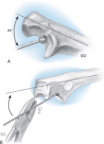
Ulnar Preparation
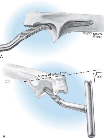
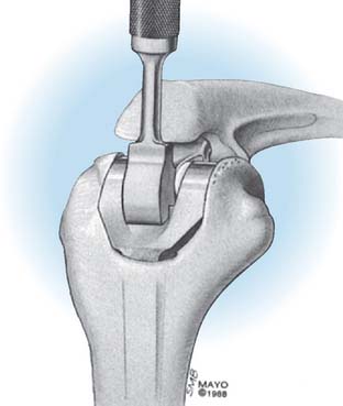
The medullary canal of the ulna is identified by using a high-speed burr at about a 45-degree angle to the base of the coronoid (Fig. 53-15). The tip of the olecranon is removed, notched, or both, to allow identification of the canal by a small reamer. An appropriately sized rasp is then used, and a mallet is generally required to remove the subchondral bone around the coronoid (Fig. 53-16). The rasp handle is maintained at an orientation perpendicular to the plane of the “flat” of the proximal ulna. This corresponds to the flexion axis and serves to accurately orient the ulnar component. If the canal is tight, flexible reamers are available to prepare and expand the medullary cavity.
Trial Reduction
A trial reduction allows assessment of depth of insertion and soft tissue restriction to extension. The ulna is inserted to the depth that corresponds to the axis of the implant replicating the axes flexion (Fig. 53-17).
Implant Insertion
The cement is first injected down the humeral medullary canal to a depth determined by the length of the humeral stem (Fig. 53-18). The cement is then injected down the ulnar canal.
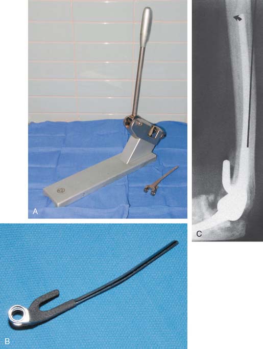
A bone graft is prepared from the excised trochlea or from the bone bank for revision surgery. The graft should measure about 3 to 4 mm in thickness and should be about 2 cm long and 1.5 cm wide. The bone graft is placed anterior to the anterior cortex of the distal humerus, and the humeral component is inserted down the canal to a point that allows articulation of the device at a level where the bone graft is partially covered by the flange as well (Fig. 53-19). If the canal is tight, the anterior bow of the humerus is accommodated by making a slight bow in the humeral stem with the plate bender (Fig. 53-20).
The ulnar component is articulated with the humeral device by placing the hollow axis through the humerus and ulna and securing it with the solid pin inserted from the opposite direction (Fig. 53-21). After the prosthesis has been coupled, the ulna is placed at a 90-degree angle, and the humeral component is impacted down the medullary canal (Fig. 53-22). In general, the device is inserted to a point at which the axis of rotation of the prosthesis is at the level of the normal anatomic axis of rotation. This is approximated when the base of the flange is flush to the anterior bone of the olecranon fossa and the distal aspect of the humeral component is flush or slightly proximal to the distal aspect of the capitellum.
The Triceps
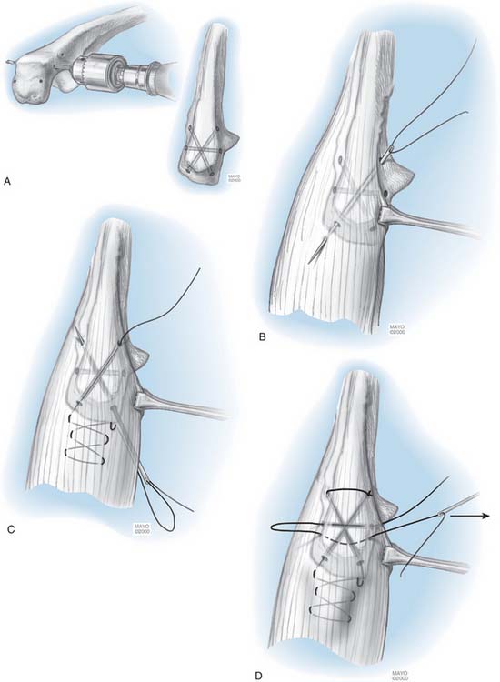
If the triceps has been reflected, it is secured to the ulna with a heavy (No. 5) nonabsorbable suture. The first stitch penetrates the lateral tendon in the reduced position and is locked. A second locked throw is placed in the medial tendon, the suture then penetrates the tendon in line with the proximal medial tunnel. It passes through the tunnel from proximal medial to distal lateral. It then is brought through the soft tissue there and is tied to itself. An additional transverse suture is placed across the olecranon, locks at the posterior aspect of the olecranon in the center portion of the tendon and is tied to itself (Fig. 53-23). Sutures are tied beneath the tendon because were they subcutaneous, they might irritate or cause stitch abscess.
POSTOPERATIVE MANAGEMENT
The arm is elevated postoperatively for 24 hours, with the elbow above shoulder level. If drains are used, they are removed after approximately 24 hours, and the compressive dressing is removed 24 hours later. A light dressing is applied, and elbow flexion and extension are allowed, as tolerated. A collar and cuff are used, and the patient is allowed to begin activities of daily living. No formal physical therapy is required or indicated. Strength exercises are avoided. Typically, the patient leaves the hospital on the third day and is advised not to lift more than 0.5 kg over the next 3 months. We typically recommend that the patient not lift more than 4 to 5 kg with the operated arm as a single event, or more than 1 kg repeatedly. If a flexion contracture greater than 45 degrees existed before surgery, an extension turnbuckle splint is regularly used at night for 4 to 12 weeks.
RESULTS
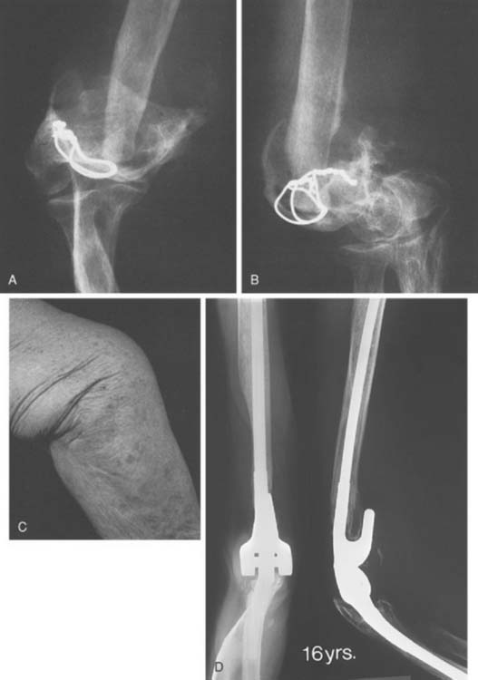
Experience with this device for several conditions is discussed in subsequent chapters. The intermediate and long-term experience is emerging for those with rheumatoid arthritis (Fig. 53-24) and for post-traumatic conditions (Fig. 53-25). The results remain gratifying.
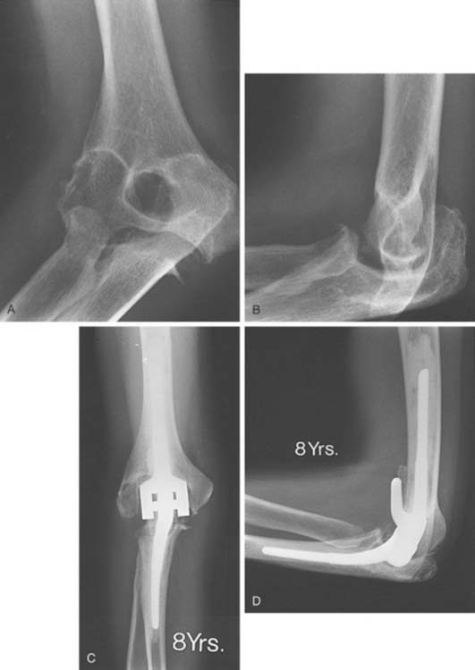
FIGURE 53-24 A and B, Patient with severe grade III rheumatoid arthritis. C and D, Excellent 8-year result after replacement.
1 Adams, R. A., and Morrey, B. F.: The effectiveness of a compressive Cryocuff after elbow surgery. A prospective randomized study. Presented at the annual meeting of the AAOS, Anaheim, CA, February 1999.
2 Bell S., Gschwend N., Steiger U. Arthroplasty of the elbow. Experience with the Mark III GSB prosthesis. Aust. N.Z. J. Surg. 1986;56:823.
3 Brownhill J.R., Furukawa K., Faber K.J., Johnson J.A., King G.J.W. Surgeon accuracy in the selection of the flexion-extension axis of the elbow. An in vitro study. J. Shoulder Elbow Surg. 2006;15:451.
4 Brumfield R.H., Kuschner S.H., Gellman H., Redix L., Stevenson D.V. Total elbow arthroplasty. J. Arthroplasty. 1990;5:359.
5 Bryan R.S., Morrey B.F. Extensive posterior exposure of the elbow. A triceps-sparing approach. Clin. Orthop. Relat. Res. 1982;166:188.
6 Duggal N., Dunning C.E., Johnson J.A., King G.J.W. The flat spot of the proximal ulna: a useful anatomic landmark in total elbow arthroplasty. J. Shoulder Elbow Surg. 2004;13:206.
7 Ewald F.C., Scheinberg R.D., Poss R., Thomas W.H., Scott R.D., Sledge C.B. Capitellocondylar total elbow arthroplasty: 2- to 5-year follow-up in rheumatoid arthritis. J. Bone Joint Surg. 1980;62A:125.
8 Faber K.Y., Cordy M.E., Milne A.D., Chess D.G., King G.J., Johnson J.A. Advanced cement technique improves fixation in elbow arthroplasty. Clin. Orthop. 1997;334:150.
9 Figgie M.P., Inglis A.E., Mow C.S., Figgie H.E.III. Salvage of nonunion of supracondylar fracture of the humerus by total elbow arthroplasty. J. Bone Joint Surg. 1988;3:235.
10 Figgie H.E.III, Inglis A.E., Ranawat C.S., Rosenberg G.M. Results of total elbow arthroplasty as a salvage procedure for failed elbow reconstructive operations. Clin. Orthop. Relat. Res. 1987;219:185.
11 Friedman R.J., Ewald F.C. Arthroplasty of the ipsilateral shoulder and elbow in patients who have rheumatoid arthritis. J. Bone Joint Surg. 1987;69A:661.
12 Friedman R.J., Lee D.E., Ewald F.C. Nonconstrained total elbow arthroplasty: development and results in patients with functional class IV rheumatoid arthritis. J. Arthroplasty. 1989;4:31.
13 Gill D., Morrey B.F. The Coonrad-Morrey total elbow arthroplasty in patients with rheumatoid arthritis: a 10-15 year follow-up study. J. Bone Joint Surg.. 1998;80A:1327.
14 Gschwend N., Loehr J., Ivosevic-Radovanovic D., Scheier H., Munzinger U. Semiconstrained elbow prostheses with special reference to the GSB III prosthesis. Clin. Orthop. Relat. Res. 1988;232:104.
15 Johnson J.R., Getty C.J.M., Lettin A.W.F. The Stanmore total elbow replacement for rheumatoid arthritis. J. Bone Joint Surg. 1984;66B:732.
16 Madsen F., Gudmundson G.H., Søjbjerg J.O., Sneppen O. The Pritchard-Mark II elbow prosthesis in rheumatoid arthritis. Acta Orthop. Scand. 1989;60:249.
17 Morrey B.F. The Elbow and Its Disorders. Philadelphia: W. B. Saunders Co., 1985.
18 Morrey B.F. Semi-constrained total elbow arthroplasty. In: Morrey B.F., editor. Joint Replacement Arthroplasty. New York: Churchill Livingstone; 1991:311.
19 Morrey B.F., Adams R.A., Bryan R.S. Total replacement for posttraumatic arthritis of the elbow. J. Bone Joint Surg. 1991;73B:607.
20 Morrey B.F., Adams R.A. Semiconstrained elbow replacement for rheumatoid arthritis. J. Bone Joint Surg. 1992;74A:479.
21 Morrey B.F., Adams R.A. Semiconstrained elbow replacement for distal humeral nonunion. J. Bone Joint Surg Br. 1995;77:67-72.
22 Morrey B.F., Askew L.J., An K.N. Strength function after elbow arthroplasty. Clin. Orthop. Relat. Res. 1988;234:43.
23 Morrey B.F., Bryan R.S., Dobyns J.H., Linscheid R.L. Total elbow arthroplasty: a five-year experience at the Mayo Clinic. J. Bone Joint Surg. 1981;63A:1050.
24 O’Driscoll S., An K., Morrey B.F. The kinematics of elbow semiconstrained joint replacement. J. Bone Joint Surg. 1992;74B:297.
25 Risung F.. Characteristics, design and preliminary results of the Norway Elbow System. Hämäläinen M., Hagena F.-W., editors. Rheumatoid Arthritis Surgery of the Elbow. Rheumatology, Vol 15. Karger, Basel, 1991;68.
26 Schuind F., O’Driscoll S., Korinek S., An K.N., Morrey B.F. Loose-hinge total elbow arthroplasty: an experimental study of the effects of implant alignment on three-dimensional elbow kinematics. J. Arthroplasty. 1995;10:670.
27 Wolfe S.W., Ranawat C.S. The osteo-anconeus flap. J. Bone Joint Surg. 1990;72A:684.
[/level-membership-for-orthopaedics-category][not-level-membership-for-orthopaedics-category]
CHAPTER 53 Linked Elbow Arthroplasty: Rationale, Indications, and Surgical Technique
INTRODUCTION
As noted in Chapter 52 and further described in Chapters 54 through 60, the results of total elbow arthroplasty are improving with increased basic knowledge of elbow mechanics,24 better designs, and greater surgical experience.21 The general principles of the surgical technique and improved designs2,9,14,18,24 and a detailed description of my specific method of inserting the Coonrad-Morrey implant are presented. The results of semiconstrained joint replacement arthroplasty emphasize the Mayo Clinic experience with the modified Coonrad device.
RATIONALE
The selection and the rationale for unlinked elbow replacement are described in Chapter 52. The reason for continuing to use a semiconstrained linked implant is simple: the current design works well, is reproducible, and can address a broad spectrum of pathology. The Coonrad-Morrey linked device and similar implants are distinctly different, both conceptually and clinically, from the original, fully constrained articulated devices. In today’s linked prostheses, the one feature in common is that the ulnar component is coupled to the humerus with angular and rotatory laxity of 5 to 10 degrees (Fig. 53-1). The theoretical advantage has been confirmed in the laboratory in which it was demonstrated that the articulation tracks within the limits of its tolerance (Fig. 53-2). This decreases stresses on the bone-cement interface.24 Documentation of improved clinical results attests to the effectiveness of the semiconstrained linked design.2,4,13,14,16,18,21 Of particular note is that the linked implant dramatically broadens the indications for reconstructive surgery of the elbow. Whereas unlinked devices may be very effective for rheumatoid arthritis, the potential for instability limits their use when deformity and osseous and ligamentous deficiency is present. The linked implant may be used with equal effectiveness in patients with rheumatoid arthritis,20 for post-traumatic arthrosis,19 and for revision surgery.18 The enhanced stability supplied by the coupling is provided without transmission of excessive stress to the bone-cement interface with the semiconstrained design.24
CONTRAINDICATIONS
As for any total elbow arthroplasty, the absolute contraindications for a linked arthroplasty are active infection, inadequate soft tissue protection, and the lack of adequate motor muscle power to flex the elbow to ensure proper functioning of the device. Relative contraindications are lack of patient compliance. Primary degenerative joint disease is also a relative contraindication because patients with this disease are usually younger and active, and alternative selections are effective (see Chapter 60). High demand and a dysfunctional hand are also relative contraindications for total elbow arthroplasty.
PRINCIPLES OF SURGICAL TECHNIQUE
SURGICAL INCISION
A straight posterior skin incision is preferred. If a previous incision is present it is employed when possible. If the patient is older than 4 or 5 years of age, it may be repaired if it cannot be incorporated. The incision need not and should not be curved.
THE ULNAR NERVE
Opinions are divided with respect to the management of the ulnar nerve. Some surgeons believe that it should not be exposed,7,9,12,16,27 whereas today most believe that the ulnar nerve should be directly visualized and moved as an integral part of the surgical approach and procedure.4,10,15,23 We favor the latter philosophy.
THE TRICEPS
The fascial tongue exposure of Campbell (Van Gorder) causes a good deal of soft tissue dissection, with a significant amount of dead tissue that provides an environment favorable to infection, which may result in weakness.5,22 Splitting the triceps in the midline is enjoying a resurgence of popularity. In our experience, this tends to cause detachment of the medial insertion. Therefore, I continue to prefer the Mayo technique of reflecting the triceps in continuity with the ulnar periosteum and forearm fascia described by Bryan and Morrey.5 The important point, however, is a meticulous repair (see later).
AXIS OF ROTATION
The philosophy of the Coonrad-Morrey device is to use the most reliable landmark to serve as the basis for defining the flexion axis. The landmark selected for this system is the anterior cortex to establish the anterior/posterior position of the axis. The roof of the coronoid fossa is the anatomic reference for depth of insertion, and the plane of the columns define the rotation of the axis of the humeral component (Fig. 53-3).
CEMENTING TECHNIQUE
The cement should be introduced down the medullary canal for stemmed implants with an injection system. Generally speaking, injector systems have dramatically improved the radiographic appearance of the bone-cement interface. It was shown in our early experience20,23 and subsequently Faber,8 that the quality of the cementing technique is inversely related to the presence of lucent lines, and, ultimately, to implant loosening (Fig. 53-4).
TRICEPS REATTACHMENT
Triceps reattachment has emerged as a major emphasis for all elbow joint replacement surgery. Whenever the triceps is reflected from its attachment, it must be securely reattached to the olecranon by nonabsorbable sutures placed through bone. The sutures should be tied with the elbow in 90 degrees of flexion, but knots are avoided over the subcutaneous border of the ulna. Because the attachment communicates with the joint and motion will allow the synovial fluid to become interposed between the triceps and the olecranon, an attachment may be compromised. The transverse “cinch” suture applies the tendon to the olecranon. To enhance strength and ensure continuity, we also tend to displace the extensor mechanism slightly medially, if possible, bringing the anconeus slightly over the proximal ulna.
POSTOPERATIVE DRESSING
We have had virtually no incision problems because we have been routinely placing the elbow in full extension with an anterior splint and elevating the arm for approximately 24 hours. We see no advantage to allowing the elbow to assume 90 degrees of flexion immediately after surgery. Because of continued concern for the variable swelling and occasional blistering that may occur after surgery, I no longer use the Steri-Drape, and I avoid Betadine solution if the barrier drape is used. A prospective, randomized study recently revealed statistically measurable decreases in swelling after surgery with the use of a compression Cryocuff (Aircast Co., Coconut Creek, FL).1
THE SEMICONSTRAINED LINKED IMPLANT
Today, in the United States, several semiconstrained elbow replacements are commercially available, including the Coonrad-Morrey (Zimmer, Warsaw, IN), the Latitude (Tornier, Edina, MN), and the Discovery (Biomet, Warsaw, IN). To date, these two implants have not had sufficient use to document outcomes. The GSB III has evolved through the years and has been frequently used in Europe but its use and support is being discontinued (Fig. 53-5). Experience with the GSB III devices is discussed under the appropriate indications in subsequent chapters. Risung25 has also reported favorable outcomes with a rather novel implant designed termed the Norway elbow.
