[level-membership-for-neurosurgery-category]
Chapter 21 Lateral Approaches to Cervicothoracic Junction
RADIOLOGICAL IMAGING FOR CERVICOTHORACIC JUNCTION AREA
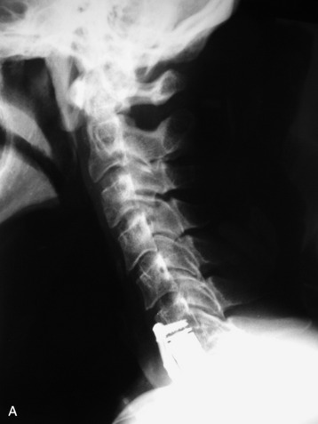
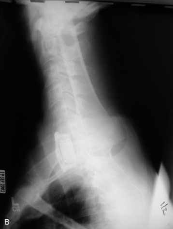
As a simple radiological study, three serial views (anteroposterior [AP] and both lateral views) are commonly used in the cervical spine. At the cervicothoracic junction, the shoulder joint may preclude the correct imaging of the lesion (Fig. 21-1, A). Radiography of this region that allows adequate visualization may be technically difficult to obtain, and in at least 30% of the patients the C7–T1 space is not visualized on the three-view series.1 The bilateral oblique view and swimmer’s views can be helpful in this situation. In patients for whom the standard AP and lateral view series fails to demonstrate the cervicothoracic junction, swimmer’s views and supine oblique views show the alignment of the vertebral bodies with equal frequency (Fig. 21-1, B). However, supine oblique films are safer, expose patients to less radiation, and are more often successful in demonstrating the posterior elements at the cervicothoracic junction.1
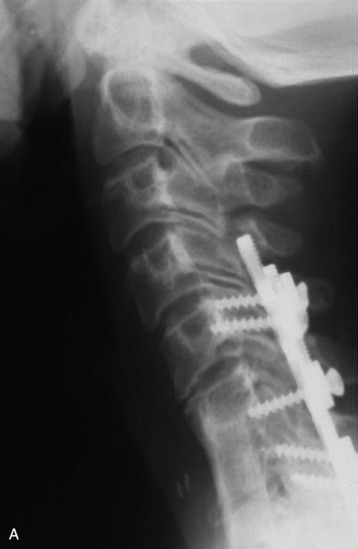
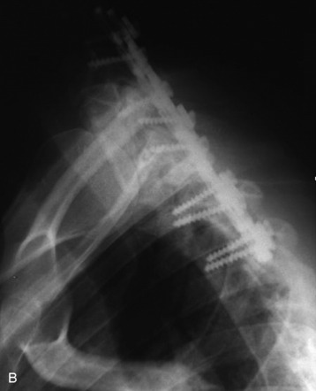
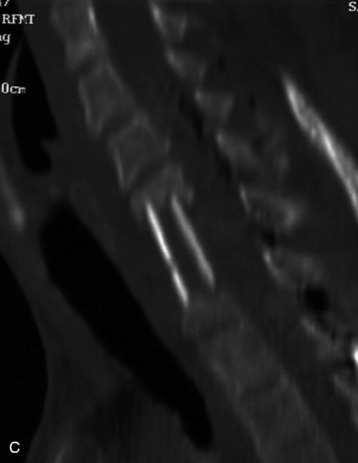
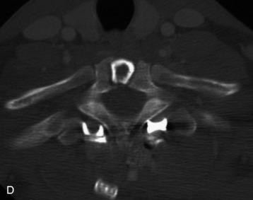
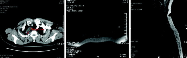
When the corpectomy is performed at the C7 and T1 levels, the graft position is not evaluated with a simple lateral view (Fig. 21-2, A). With the oblique view, the alignment can be recognized with relative ease (Fig. 21-2, B). For the adequate evaluation of the C7–T1 region, a computed tomography (CT) scan is superior to simple radiography and has several advantages. It shows correct anatomical structures around the transverse process and rib head complex. It also provides sagittal reconstruction, which enables the surgeons to decide the correct position of the graft and instrument. If the CT scan is performed, the correct position of the bone graft and instrument is easily seen with axial and sagittal scans (Fig. 21-2, C and D).
POSTEROLATERAL PARASCAPULAR APPROACH TO UPPER THORACIC SPINE (TRANSTHORACIC, TRANSPLEURAL THIRD RIB RESECTION APPROACH)
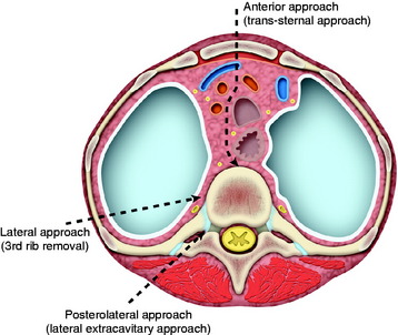
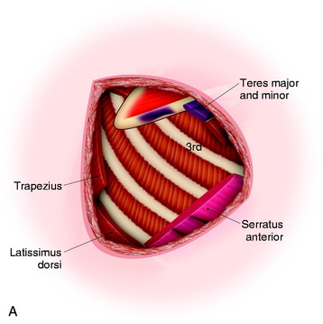
A small thoracotomy through the third rib bed provides access to the retromediastinal space of the cervicothoracic junction (Fig. 21-3). This approach can be accessed with the posterolateral or anterolateral route. The posterolateral approach has several advantages over the anterolateral one. The posterolateral approach can expose the cervical region simultaneously and allow posterior fusion surgery if necessary. It provides a shorter access than the anterior route.
Position and Incision
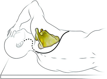
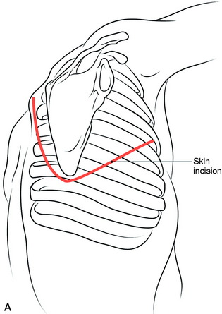
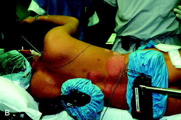
The patient is in the lateral decubitus position with the upper limb of the same side hanging in front of the thorax to encourage the maximum displacement of the scapula (Fig. 21-4). The right side approach is preferred to left side approach below the T4 level because greater vessels can be avoided. At the levels of T1–3 the greater vessels are not encountered, so the approach side is selected according to the lesion side.2 A curve commencing at the tip of the spinous process around the posterior angle of the scapula continues along its vertebral border and runs forward 2 or 3 cm above its tip to pass along the line of the fifth rib.1
Muscle Dissection
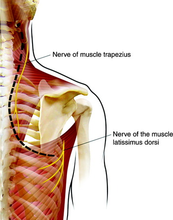
The muscles that connect the spine to the scapula are the trapezius, rhomboid, and levator scapulae. The trapezius muscle is incised along the medial border of the scapula. The division should be made not more than two fingers breadth from the spine to prevent injury of the spinal accessory nerve (Fig. 21-5). Inferior fibers of the trapezius muscle should be transected for the flap to be reflected. The rhomboids are then detached from the vertebral border of the scapula. Then the scapula is mobilized and lifted up, while the surgeon pulls upward and forward with a self-retaining hook. The levator scapulae muscle should be transected for the exposure of the lower cervical region. The entire group of erector spinae muscle and transversospinalis muscle can be dissected off the spinous process, laminae, facets, and transverse processes as a single muscular mass. The insertion of the iliocostalis thoracis muscle also is taken down.
Rib Resection
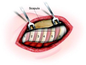
The intercostal muscles and soft tissue are stripped from the rib. In those tissues, the intercostal artery, vein, and nerve are included. Underneath the rib, a vein is located just below the bone, and artery and nerve are arranged from cephalad to caudad order. The ribs that are involved to the surgical lesion are resected 5–6 cm lateral to the junction of the rib with the transverse process (Fig. 21-6).
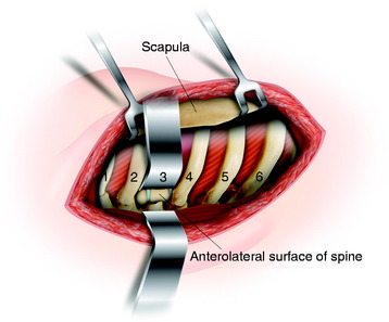
The posterior arches of the second, third, fourth, and fifth ribs are resected, which gives an excellent view of the upper thoracic vertebrae. When wide exposure is not required, the resection of the third rib only will allow for a sufficient view of the upper thoracic spine (Fig. 21-7).
Exposure of Vertebral Body
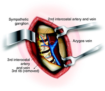
After incision of the pleura, the superior lobe of the lung retracts, giving access to the lateral border of the upper thoracic spine from T1–4. The first intercostal space is supplied by the highest intercostal artery from the costocervical trunk. This artery descends anteriorly to the ventral rami of the eighth cervical and first thoracic nerves on the necks of the fist rib. The second and third intercostal arteries arise from the same trunk from the aortic arch and divide into two branches. The remaining intercostal arteries arise from the posterior surface of the thoracic aorta. Each intercostal artery stretches obliquely across each vertebral body from caudad to cephalad in direct apposition to the periosteum of the vertebral body and is located deep to the azygos vein (right side) or hemiazygos vein (left side), the thoracic duct (left side), and the sympathetic trunk (Fig. 21-8). The azygos vein runs upward along the right side of the vertebral column, turning forward at the level of the T3–4 intervertebral space to join the superior vena cava.3
Vertebral Body Removal
The rami communicantes are transected, and the intercostal arteries are ligated and transected as well. Displacing the sympathetic chain anterolaterally via subperiosteal dissection reveals anterolateral surface of the vertebral body, pedicle, and foramen. Before vertebral body removal, pedicle resection is required. The confirmation of the intervertebral foramen allows easy pedicle resection.4 The resection of the pedicle reveals the lateral surface of the spinal cord. The surgeons can make sure the interface between the posterior margin of the vertebral body and spinal cord. The vertebral body resection is performed from the posterior side to anterior side. After corpectomy, the appropriate graft is inserted into the vertebral body defect (Fig. 21-9).
CASE ILLUSTRATION
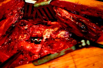
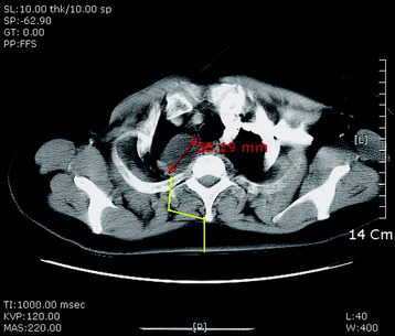
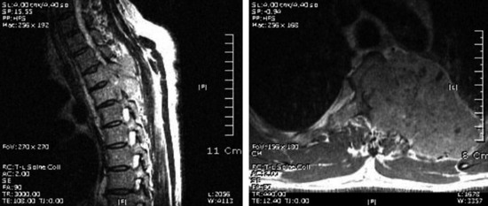
The mass was located at the right paravertebral area (T1 and T2 levels). It was a purely extraforaminal mass (Fig. 21-10). In the spinal canal, no tumor mass was found. An operation was performed with the patient in the prone position. The skin was incised in a hockey-stick shape and included a vertical midline incision and right side extension. The trapezius muscle was cut from the midline, and horizontal cutting was added according to the skin incision. The rhomboid muscles were dissected horizontally and retracted in a cephalocaudal direction.
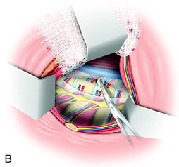
The approach was continued between the erector spinae muscle and longissimus muscle (Fig. 21-11). The costotransversectomy was performed at the T1 and T2 levels. The right transverse processes of T1 and T2 were resected, and the proximal rib head was removed.
ANTEROLATERAL TRANSTHORACIC, TRANSPLEURAL THIRD RIB RESECTION APPROACH
Position and Incision
General endotracheal anesthesia is introduced and a double lumen tube is used for one lung ventilation. The patient is placed in the lateral decubitus position with the appropriate side up, as done in the posterolateral approach. The entire upper extremity is prepped and draped sterilely out of the operative field. The skin is incised from the paraspinous area at approximately T1, and the incision is extended distally along the medial border of the scapula to the seventh rib. This incision is continued first laterally, then anteriorly, then medially to the costal cartilage of the third rib (Fig. 21-12).
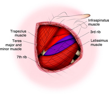
After the skin incision is made, the superficial muscles (trapezius and latissimus dorsi) are seen (Fig. 21-13). Mobilization of the scapula for exposure of the high thoracic region will require detachment of the posterior musculature and associated tendinous attachments to the posterior inferior medial scapular border.
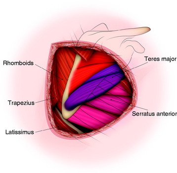
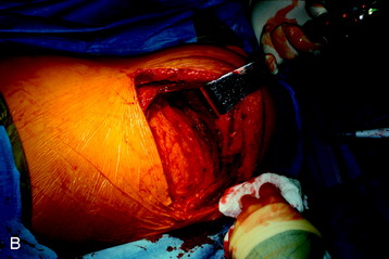
Muscles detached during exposure are the serratus anterior (anteroinferior side), latissimus dorsi (inferior-medial border of the scapula), trapezius, and rhomboid major and minor (medial-posterior border). The trapezius and latissimus dorsi muscles are divided, after which the rhomboid, infraspinatus, teres major, and serratus anterior muscles appear (Fig. 21-14). The teres major muscles are cut, and the serratus anterior muscles are divided for the anterior release of the scapula, after which the scapula can be retracted posteriorly (Fig. 21-15). The upper thoracic rib beds can be identified after division of the serratus anterior. Care should be taken to identify and preserve the long thoracic nerve.
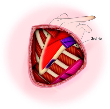
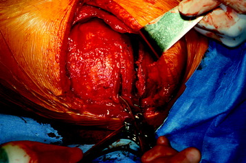
The scapula is then retracted cephalad and medially using a scapular retractor to expose the subscapular space (Fig. 21-16, A). Scapula retraction requires a very strong force. The subscapular space is entered once the superficial muscles have been detached and the scapula mobilized and retracted in a cephalad direction. Once the scapula is retracted, identification of the third rib is possible (Fig. 21-16, B). When counting ribs, the first rib usually is located inside the second rib and can be missed. The rib corresponding to the inferior tip of the scapula is usually the seventh rib. The rib count can be done from the caudad or cephalad side. With the aid of fluoroscopy, the correct rib count is possible. The ribs are attached to one another through the intercostal musculature, which originates medially on each superior rib and inserts laterally on its immediately inferior rib.
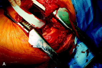
Resection of the third rib will allow for greater intercostal spreading than would a second rib resection. After the third rib is identified, it is resected as far anteriorly and posteriorly as possible (Fig. 21-17). The third rib bed, consisting of periosteum, endothoracic fascia, and parietal pleura, is identified and transected to enter the thoracic cavity. The parietal pleura overlying the ribs and spinal column is identified and can be opened by incising from the costochondral cartilage to the mid-vertebral body (Fig. 21-18).
CASE ILLUSTRATION
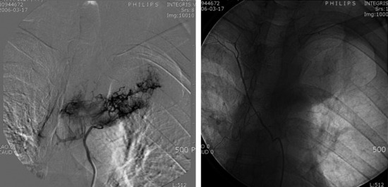
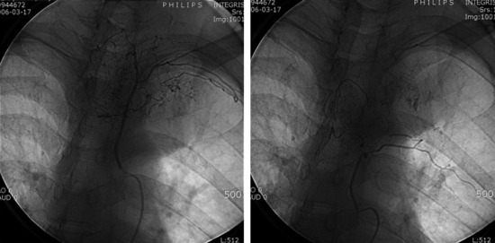
A 46-year-old male patient presented with interscapular pain with left side upper thoracic pain. An MRI showed a large tumor involving the T3 and T4 vertebral bodies extending to the left side third rib (Fig. 21-19). Results of percutaneous needle biopsy for the rib mass proved to be hepatocellular carcinoma. The diagnosis was confirmed with abdominal CT. For the surgical decompression, angiography was performed. On angiography, the second, third and fourth intercostal arteries originated from the aorta at the level of T5 (Fig. 21-20). These arteries go up straight to the head of the each rib. At the head of the rib, the intercostal arteries turn in direction toward the lateral side and run under the lower margin of the rib (Fig. 21-21). When the surgical approach is attempted from the anterolateral direction, the second, third, fourth, and fifth intercostal arteries can be ligated at the level of the T5 and T6 vertebral bodies. This procedure can help lessen the intraoperative bleeding tremendously during tumor mass removal.
[/level-membership-for-neurosurgery-category][not-level-membership-for-neurosurgery-category]
Chapter 21 Lateral Approaches to Cervicothoracic Junction
RADIOLOGICAL IMAGING FOR CERVICOTHORACIC JUNCTION AREA
As a simple radiological study, three serial views (anteroposterior [AP] and both lateral views) are commonly used in the cervical spine. At the cervicothoracic junction, the shoulder joint may preclude the correct imaging of the lesion (Fig. 21-1, A). Radiography of this region that allows adequate visualization may be technically difficult to obtain, and in at least 30% of the patients the C7–T1 space is not visualized on the three-view series.1 The bilateral oblique view and swimmer’s views can be helpful in this situation. In patients for whom the standard AP and lateral view series fails to demonstrate the cervicothoracic junction, swimmer’s views and supine oblique views show the alignment of the vertebral bodies with equal frequency (Fig. 21-1, B). However, supine oblique films are safer, expose patients to less radiation, and are more often successful in demonstrating the posterior elements at the cervicothoracic junction.1
When the corpectomy is performed at the C7 and T1 levels, the graft position is not evaluated with a simple lateral view (Fig. 21-2, A). With the oblique view, the alignment can be recognized with relative ease (Fig. 21-2, B). For the adequate evaluation of the C7–T1 region, a computed tomography (CT) scan is superior to simple radiography and has several advantages. It shows correct anatomical structures around the transverse process and rib head complex. It also provides sagittal reconstruction, which enables the surgeons to decide the correct position of the graft and instrument. If the CT scan is performed, the correct position of the bone graft and instrument is easily seen with axial and sagittal scans (Fig. 21-2, C and D).
POSTEROLATERAL PARASCAPULAR APPROACH TO UPPER THORACIC SPINE (TRANSTHORACIC, TRANSPLEURAL THIRD RIB RESECTION APPROACH)
A small thoracotomy through the third rib bed provides access to the retromediastinal space of the cervicothoracic junction (Fig. 21-3). This approach can be accessed with the posterolateral or anterolateral route. The posterolateral approach has several advantages over the anterolateral one. The posterolateral approach can expose the cervical region simultaneously and allow posterior fusion surgery if necessary. It provides a shorter access than the anterior route.
Position and Incision
The patient is in the lateral decubitus position with the upper limb of the same side hanging in front of the thorax to encourage the maximum displacement of the scapula (Fig. 21-4). The right side approach is preferred to left side approach below the T4 level because greater vessels can be avoided. At the levels of T1–3 the greater vessels are not encountered, so the approach side is selected according to the lesion side.2 A curve commencing at the tip of the spinous process around the posterior angle of the scapula continues along its vertebral border and runs forward 2 or 3 cm above its tip to pass along the line of the fifth rib.1
Muscle Dissection
The muscles that connect the spine to the scapula are the trapezius, rhomboid, and levator scapulae. The trapezius muscle is incised along the medial border of the scapula. The division should be made not more than two fingers breadth from the spine to prevent injury of the spinal accessory nerve (Fig. 21-5). Inferior fibers of the trapezius muscle should be transected for the flap to be reflected. The rhomboids are then detached from the vertebral border of the scapula. Then the scapula is mobilized and lifted up, while the surgeon pulls upward and forward with a self-retaining hook. The levator scapulae muscle should be transected for the exposure of the lower cervical region. The entire group of erector spinae muscle and transversospinalis muscle can be dissected off the spinous process, laminae, facets, and transverse processes as a single muscular mass. The insertion of the iliocostalis thoracis muscle also is taken down.
Rib Resection
The intercostal muscles and soft tissue are stripped from the rib. In those tissues, the intercostal artery, vein, and nerve are included. Underneath the rib, a vein is located just below the bone, and artery and nerve are arranged from cephalad to caudad order. The ribs that are involved to the surgical lesion are resected 5–6 cm lateral to the junction of the rib with the transverse process (Fig. 21-6).
[/not-level-membership-for-neurosurgery-category]
