57 Imaging of the Chest
 Principles of Imaging in the Intensive Care Unit
Portable chest radiography plays a major role in patient care, especially in critically ill patients. Bedside chest radiographs are frequently obtained in ICU patients, and an understanding of how to interpret these films is important for ICU physicians. The American College of Radiology’s current guidelines call for daily chest radiographs of all mechanically ventilated patients in the ICU,1 but this approach is controversial. Some earlier studies supported this recommendation, arguing that early detection of unexpected findings on routine films may save money and decrease length of stay.2–4 However, several recent and larger studies have refuted this, demonstrating that a small minority of routine chest radiographs have any significant impact on patient management. Further, these studies suggest that transition to on-demand imaging saves money and radiation exposure without prolonging length of stay or negatively impacting other safety parameters.5–10
 Conventional and Digital Radiography
With conventional portable radiography units, the maximum tube current and voltage are limited, so exposure times are relatively long, and image contrast may be excessive. Digital (or computed) radiography uses a phosphor plate in lieu of a film-screen combination to capture and store the radiographic image, which reduces the patient’s radiation dose. When digital images are processed, the portion of the dynamic range containing the diagnostic information is identified, and the final output for display is adjusted to a consistent and optimized contrast and density. This obviates the need for repeated examinations because of errors in exposure and may improve diagnostic yield.11 For these reasons, as well as the ease with which digital processing allows placement of images on a digital network, digital radiography has largely replaced conventional techniques.
Conventional and digital radiography share some disadvantages, however. The overall time required for obtaining the radiograph remains the same, and both portable techniques capture images in the anteroposterior projection. When combined with a shorter source image receptor distance, this leads to geometric magnification of anterior chest structures such as the heart. In addition, severe patient illness in the ICU often requires supine and semi-upright positioning, which may complicate interpretation of radiographs, particularly in cases of pneumothorax or pleural effusion.12
 Computed Tomography
Computed tomography provides better anatomic detail and a higher degree of diagnostic accuracy than chest radiography, but for critically ill patients, transportation and cumbersome monitoring devices limit access to CT. Mobile CT scanners have been developed to image critically ill patients in the ICU and avoid the need for transportation. They are not yet in widespread use, in part due to image quality concerns, but have demonstrated utility in neurosurgical13–16 and other intensive care applications,17 including infectious disease outbreak situations.18
 Picture Archiving and Communications System
 Interpreting the ICU Chest Radiograph
Monitoring and Support Devices
Endotracheal Tubes
On the chest radiograph, the position of an endotracheal tube (ETT) is determined by the location of the tube’s tip in relation to the carina with respect to the position of the patient’s chin. With the chin in the neutral position, the tip of the ETT should be 3 to 7 cm above the carina (Figure 57-1). Alternatively, the tip of the ETT should project over the T3 or T4 vertebral body, because the carina is located between T5 and T7 on anteroposterior radiographs in most individuals. Neck flexion and extension can result in 2 cm of downward or upward displacement, respectively, of the ETT.19 Projection of the anterior portion of the mandible over the lower cervical spine indicates neck flexion, whereas an unobscured cervical spine indicates neck extension.

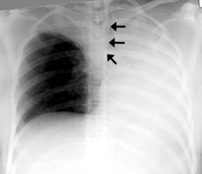
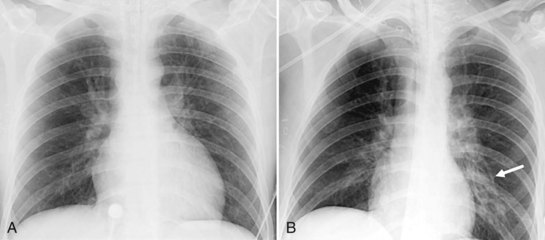
The most common complication of ETT placement is inadvertent intubation of the right main bronchus (Figure 57-2) because of its shallower angle of departure from the trachea compared to the left main bronchus. Esophageal placement of the ETT can occur, although this is usually detected on physical examination. Radiographic findings of esophageal intubation include direct visualization of the ETT lateral to the tracheal wall, gaseous distention of the stomach, and displacement of the trachea by an overdistended balloon cuff.
Tracheostomy Tubes
The tip of a tracheostomy tube should be several centimeters above the carina, and the tube’s diameter should be approximately two-thirds that of the trachea.20 Unlike ETTs, chin position does not affect tracheostomy tube position. Air is commonly seen in the subcutaneous tissue of the neck and upper mediastinum immediately after tracheostomy tube placement and should resolve over time. Pneumothorax and mediastinal hematoma, the latter manifesting as a dense mediastinum with full, convex margins, are more worrisome complications of tracheostomy tube placement that should not be overlooked.
Central Venous Catheters
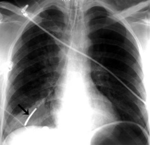
Central venous catheters are inserted from an internal jugular (IJ), subclavian (SC), or femoral approach. The optimal location of an IJ or SC catheter tip is within the superior vena cava downstream of the central venous valves. On the anteroposterior chest radiograph, the origin of the superior vena cava usually lies to the right of midline at the level of the first intercostal space (see Figure 57-1).21 The catheter tip should remain proximal to the right atrium to reduce the risk of arrhythmias, myocardial perforation, or cardiac tamponade. Portable chest radiographs should be obtained immediately after central venous catheter placement to determine catheter position and identify any complications such as pneumothorax, vessel perforation (Figure 57-3), cardiac perforation, retained or fragmented catheter, or a knotted catheter.
Peripherally Inserted Central Catheters
Peripherally inserted central catheters (PICCs) are relatively new devices gaining widespread acceptance for long-term central venous access. The catheters are small, 2 to 5 French, and are placed into the superior vena cava through a large upper-extremity vein. PICCs may be difficult to identify on bedside chest radiographs because of their small size and faint opacity. They are also more susceptible to displacement than other intravenous catheters, owing to increased flexibility of the material (see Figure 57-3).
Pulmonary Artery Catheters
Pulmonary artery catheters measure intracardiac and intrapulmonary pressures reflecting volume status, cardiac function, and vascular tone. Their use is declining in many ICUs because recent studies demonstrate limited utility in affecting patient outcomes in a variety of clinical settings.22,23 Nevertheless, when they are used, accurate placement is critical for proper interpretation. The catheters are usually introduced via an internal jugular or subclavian approach; less commonly they may be inserted through the femoral vein. They then traverse the central venous system into the right ventricle, through the pulmonic valve into the main, then right (less commonly left) pulmonary artery, then “wedge” in a proximal interlobar artery. If the tip extends beyond these larger arteries (Figure 57-4), pulmonary infarction from occlusion of the pulmonary vessel or development of a pseudoaneurysm can ensue. The balloon at the catheter tip should be inflated only during placement or when obtaining pressure measurements, so an inflated balloon should never be present on a portable chest radiograph. Complications are similar to those that occur with other central venous catheters but also include pulmonary vascular perforation and pulmonary hemorrhage.
Thoracostomy Tubes
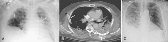
Thoracostomy tubes are placed in the pleural space to drain fluid or air. On a chest radiograph, the side port of a thoracostomy tube is marked by a disruption in the radiographically opaque line and should be located medial to the inner margin of the ribs. A malpositioned thoracostomy tube is often suspected when the tube does not drain as expected. It may not be inserted into the pleural space at all but instead tunnel through the subcutaneous soft tissues. Alternatively, the tip may lie within a pulmonary fissure, or rarely within the lung parenchyma. Subcutaneous placement can be very difficult to ascertain on chest radiograph, and an intrafissural location can only be suspected when the tube follows the course of one of the pulmonary fissures. The cross-sectional nature of CT scans provides an advantage to accurately identify the course of a thoracostomy tube and its relationship to abnormal air or fluid collections (Figure 57-5).
Enteric Tubes
Enteric tubes are placed into the stomach or proximal small bowel via a transoral or transnasal approach and come in a variety of sizes and configurations (see Figure 57-1). These tubes are frequently placed in ICU patients, especially those who are endotracheally intubated. Although the best position for feeding tubes is controversial, placement distal to the pylorus may decrease the risk of aspiration.24 Usually, enteric tube position is easily determined by a chest or abdominal radiograph, although they may occasionally be obscured by excess soft tissue in obese patients. These tubes can coil in the pharynx or esophagus, putting the patient at risk for aspiration if tube feeds are initiated. Inadvertent insertion into the tracheobronchial tree (Figure 57-6) and esophageal perforation are rare but have more serious consequences.
 Approach to ICU Chest Imaging
 Lung Abnormalities
Diffuse Lung Opacities
Cardiogenic Pulmonary Edema
Several conditions can cause the pattern of homogenous lung opacity that represents, or mimics, pulmonary edema. The classic appearance of cardiogenic pulmonary edema is that of bilateral perihilar fluffy opacities, sometimes called a butterfly or bat-wing pattern, in association with an enlarged heart, engorgement of central pulmonary veins, interstitial edema, and vascular redistribution or cephalization of vessels (Figure 57-7). Pleural effusions may also be present. The opacities associated with cardiogenic pulmonary edema can fluctuate rapidly, a clue to its diagnosis. However, this classic appearance is rare in the ICU. The bat-wing pattern is seen in few patients with pulmonary edema; opacities may be asymmetrical due to variations in patient position and underlying cardiopulmonary disease, such as emphysema or mitral valve insufficiency. In addition, cephalization of the vasculature is not a very useful marker of edema in supine ICU patients. Finally, some patients, particularly those with milder disease or chronically elevated left ventricular pressures, may only have more subtle radiographic findings, such as peribronchial cuffing and indistinct vessels.25,26 Serial measurements of vascular pedicle width may be a useful adjunct indication of intravascular volume status in these patients.27
Neurogenic Pulmonary Edema
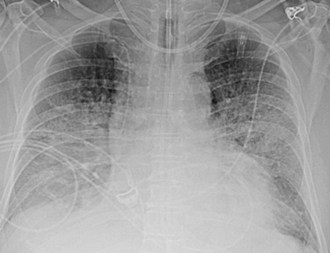
Neurogenic pulmonary edema can occur in the setting of any cerebral insult, including intracranial hemorrhage or mass, head trauma, stroke, seizures, or infection. Elevated microvascular pressure and increased vascular permeability in the lung both appear to play a role in its development.28 Neurogenic pulmonary edema can develop within hours after the neurologic insult or several days later. On the chest radiograph, neurogenic edema usually manifests as a diffuse, homogeneous pulmonary opacity similar to that of cardiogenic edema, but without an enlarged cardiac silhouette and often without the indistinct vessels that suggest engorgement. (Figure 57-8). Occasionally, opacities may have a focal distribution reflecting gravity, patient position, and heterogeneity in pulmonary venous pressure. Rapid clearing of the lungs within days of resolution of the neurologic insult is characteristic, in contrast to other forms of noncardiogenic pulmonary edema in which opacity can persist.28 It is important to note that some patients with neurologic injury are treated with large volumes of intravenous fluid, which may complicate the interpretation of pulmonary edema opacities on the chest radiograph.
Acute Lung Injury and Acute Respiratory Distress Syndrome
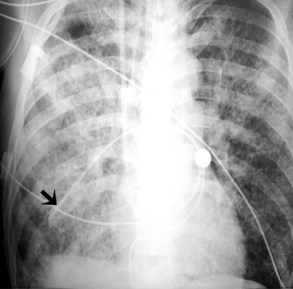
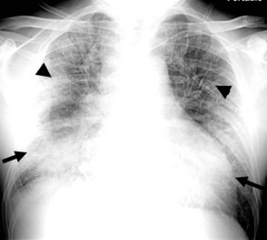
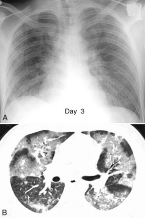
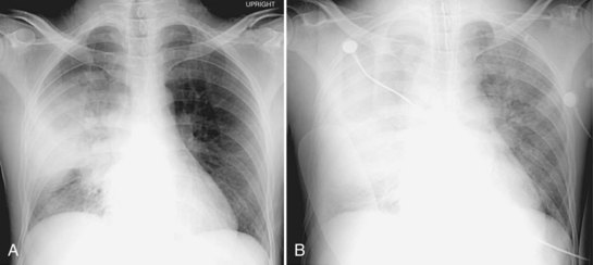
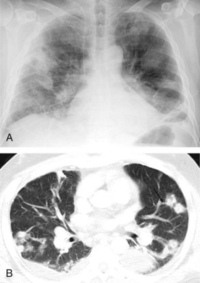
Acute lung injury (ALI) and acute respiratory distress syndrome (ARDS) are common in medical and surgical ICU patients and have a high mortality.29–31 They are clinical syndromes defined by hypoxemia and diffuse bilateral lung opacities in the absence of left atrial hypertension.32 Both result from a massive inflammatory reaction in the lungs incited by a variety of causes, and they are radiographically indistinguishable. The severity of hypoxemia alone differentiates the two, with ARDS the more severe manifestation. In the acute phase of ARDS, diffuse ill-defined opacities often predominate in the periphery of the lungs. As the disease progresses, the entire hemithorax can become opacified on chest radiographs (Figure 57-9), although CT typically demonstrates heterogeneity in lung aeration. This finding has led to much discussion regarding appropriate ventilator management of ARDS to balance alveolar recruitment while avoiding hyperinflation of spared lung tissue (see Chapter 58). During the subacute phase (5 to 10 days later), proliferation of endothelial cells and fibroblasts leads to a pattern of progressive lung destruction. Some patients recover from ARDS without any residual deficit in pulmonary function, but others progress to a chronic phase several weeks after the initial lung injury and have permanent respiratory sequelae. Fibrosis and focal emphysema are usually evident on these patients’ radiographs or CT scans.
Fat Embolism Syndrome
This syndrome is a rare but serious complication of recent severe fracture, usually of a long bone, and is characterized by pulmonary, cerebral, and cutaneous manifestations 12 to 72 hours after the injury. In mild cases, the chest radiograph often shows no abnormality. In more severe cases, the initial chest radiograph may be normal, but within 12 to 72 hours, airspace and interstitial opacities develop that resemble other causes of pulmonary edema (Figure 57-10), then resolve 10 to 14 days later in the absence of superimposed disease.33 CT scans are often not performed in these patients, but when available, variable findings including focal or diffuse areas of consolidation or “ground-glass” appearance and small nodules have all been described.34,35 Rarely, filling defects from fat emboli in pulmonary arteries are reported.36 The history of fracture, associated nonpulmonary symptoms such as a petechial rash, and delay in onset of radiographic opacities are all clues to distinguish fat embolism syndrome from other causes of a pulmonary edema pattern on chest radiographs.
Unilateral Pulmonary Edema Pattern
Postpneumonectomy pulmonary edema is described later. Reexpansion pulmonary edema (RPE) rarely follows treatment of pneumothorax or pleural effusion. It is more likely to occur if the lung has been chronically collapsed, if large volumes of air or pleural fluid (greater than 1 L) are removed rapidly, or pleural pressure drops below −20 cm H2O.37 Recent studies call these absolute numbers into question, however.38 Usually within a few hours after evacuation of air or fluid, patients develop symptoms such as cough, dyspnea, and tachypnea; hypotension due to third-spacing of edema fluid in the affected lung has been described. Chest imaging reveals diffuse homogeneous opacity on the affected side, and in rare cases, the contralateral lung may also demonstrate opacities.
Focal Lung Opacities
Aspiration
Patients with a decreased level of consciousness are at risk for aspiration. These include neurologic or neurosurgical patients who have suffered a stroke, head injury, or seizure, as well as medical or surgical patients who have esophageal disorders, altered mental status, or who have been pharmacologically sedated. The clinical severity and radiographic appearance of aspiration depend on both the amount and composition of aspirated fluid. Radiographically, aspiration can result in unilateral or bilateral lobar or multilobar opacities. Opacities tend to be in the dependent portions of the lungs, including the posterior segments of the upper lobes and the superior and posterior basilar segments of the lower lobes (Figure 57-11). Occasionally, aspirated particulate matter or foreign bodies can obstruct the airways and cause volume loss.
Pneumonia
The radiographic hallmark of community-acquired bacterial pneumonia (CAP) is lung consolidation with air bronchograms in a segmental, lobar, or (less commonly) diffuse distribution (Figure 57-12). In comparison, the majority of patients with healthcare-associated or nosocomial pneumonia (HCAP), including ventilator-associated pneumonia, are more likely to have bilateral multilobar disease.39 Radiographs typically demonstrate bronchopneumonia characterized by patchy peribronchial opacities, bronchial wall thickening, and sometimes volume loss.
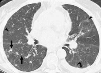
CT scanning is unnecessary in most patients with community-acquired pneumonia and a typical chest radiograph as described; in such patients, a given radiographic pattern is poorly predictive of a specific causative organism.40 CT scans may be helpful for patients whose chest radiographs are atypical or have nonresolving opacities, patients who are immunosuppressed, or patients who may require invasive procedures such as bronchoscopy. In these cases, CT can provide additional anatomic detail that may assist in identifying a pathogen or noninfectious etiology, or in guiding interventions. Ground-glass opacities are nonspecific, but airspace disease including consolidation and air bronchograms suggests bacterial, mycoplasma, or fungal pneumonia. Centrilobular nodules are infrequently found in bacterial pneumonia and instead suggest mycoplasma, fungal, or viral infection (Figure 57-13).
Chest radiography and CT may also show complications of pneumonia. Cavitation can occur in some bacterial infections, particularly in nosocomial pneumonia or immunocompromised patients, and may progress to larger abscess or pneumatocele formation. Pleural effusions are also more common in nosocomial pneumonia; a minority will become complicated and may develop into empyema (see later discussion).39
Septic Emboli
Septic emboli to the lungs come from a variety of sources, including infected right heart valves, peripheral and pelvic thrombophlebitis, and infected intravenous catheters. The usual radiographic findings of septic emboli are bilateral ill-defined nodules, predominantly in the lung periphery. These opacities classically develop at different times and show features of different stages of evolution; they often cavitate and may develop into larger abscesses. On CT, multiple lung cavitary and noncavitary nodules and wedge-shaped subpleural areas of consolidation are the usual findings (Figure 57-14).
Parenchymal Abnormalities Specific to Thoracic Surgery Patients
Pneumonectomy
Radiographs obtained immediately after pneumonectomy normally show midline position of the mediastinum and gas filling the pneumonectomy space. Over the first few days, the ipsilateral hemidiaphragm elevates, and fluid begins to accumulate within the pneumonectomy space as the gas is resorbed. In most cases, one-half to two-thirds of the hemithorax fills within the first week, and the remainder over the next several weeks to months.41 The mediastinum shifts toward the operative side as the remaining lung hyperinflates and herniates across the midline, anterior to the heart. The degree of mediastinal displacement depends primarily on the compliance and the degree of hyperinflation of the remaining lung. Appropriate mediastinal displacement is the most reliable indicator of a normal course after pneumonectomy. Failure of the mediastinum to shift to the operative side indicates an abnormality in the pneumonectomy cavity such as bronchopleural fistula, hemothorax, or empyema. Postoperative complications of pneumonectomy can occur early (within a few days of surgery) or late; in this review, we will focus on the early complications.
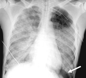
Postpneumonectomy pulmonary edema is an uncommon condition with a high mortality rate, due at least in part to an increase in pulmonary capillary permeability. Radiographic features can be mild, with peribronchial cuffing and ill-defined vascular structures. In more severe cases, the pattern is identical to that of ARDS. Bronchopleural fistula is another infrequent but life-threatening complication of pneumonectomy, which manifests with dyspnea and sometimes hemoptysis. Both pulmonary edema and bronchopleural fistula are more common after right pneumonectomy; in the latter case, the shorter length of the bronchial stump predisposes to leakage. Radiographic findings of bronchopleural fistula include persistent pneumothorax or subcutaneous and mediastinal emphysema after surgery, a decrease in height of more than 1.5 cm of the gas-fluid level in the pneumonectomy cavity, and mediastinal shift away from the operative side rather than toward it (Figure 57-15).
Parenchymal Abnormalities Specific to Trauma Patients
Pulmonary Contusion
Contusion is the most common lung injury after blunt chest trauma, occurring in up to 70% of patients.42 It is characterized by leakage of blood into the pulmonary interstitium and alveolar spaces and clinically presents with dyspnea, tachycardia, and hypoxia. On chest radiographs, the contusion manifests as pulmonary opacity in a nonanatomic distribution, in contrast to the usual segmental or lobar distribution of pneumonia or atelectasis. Contusion usually occurs in the lung periphery deep to the site of chest wall impact, although it is sometimes seen opposite the location of the injury owing to a contrecoup effect. The timing of the developing opacity on the chest radiograph suggests the diagnosis in the setting of acute trauma, presenting within the first several hours after injury and resolving within 14 days. CT is more sensitive than chest radiography for detecting pulmonary contusion as well as associated chest wall injuries.43,44 The appearance on CT of lung contusion ranges from patchy, ground-glass opacity to dense consolidation in a nonsegmental distribution, often sparing 1 to 2 mm of subpleural lung (Figure 57-16).
Pulmonary Laceration
Pulmonary laceration is characterized by frank disruption of the lung parenchyma. Radiographic features of pulmonary laceration are often masked on chest radiography by the surrounding contusion during the first few days and are better seen on CT. The appearance will change over time. In the acute phase, the hematoma within the laceration appears as a well-circumscribed, homogeneous area of soft-tissue attenuation. As the hematoma evolves, a round or elliptical gas collection called a pneumatocele becomes more obvious (see Figure 57-16). Most pneumatoceles appear within a few days, but some may develop over several weeks. They can be single or multiple and can be several centimeters in diameter. Resolution occurs over several months.
Pleural Disease
Parapneumonic Effusion and Empyema
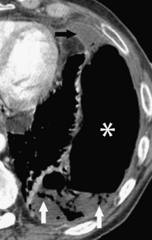
The nature of fluid within the pleural space can be difficult to determine on the chest radiograph. Pleural effusions can be transudative, exudative, purulent (empyema), bloody, or chylous. On the chest radiograph, pleural effusion causes increased opacity in the affected hemithorax, a crescentic opacity interposed between the inner margin of ribs and the lung, and an apical cap. In the setting of pneumonia, lateral decubitus films can often differentiate mobile from loculated fluid collections, with the latter suggesting active infection of the pleural space (empyema). However, loculations and gas within the pleural space, which also suggests frank empyema, are best detected on CT (Figure 57-17). Empyema can also complicate thoracic surgery, usually at least several days after the operation.
Hemothorax and Chylothorax
Hemothorax and chylothorax are most often seen in surgical patients following thoracic surgical procedures or penetrating (more common) or blunt chest trauma. Chylothorax is rare, but hemothorax occurs in up to 50% of blunt thoracic trauma.45 Either process can also complicate pneumonectomy, causing opacification of the operative hemithorax with contralateral shift of the mediastinum, in contrast to the ipsilateral shift seen with normal filling of the pneumonectomy space. Hemothorax and chylothorax are less common in the medical ICU; the former is most often an iatrogenic complication of a procedure or anticoagulation, and chylothorax usually affects oncology patients or others with thoracic duct obstruction.
Regardless of the setting, rapid opacification of the pleural space following an acute inciting event likely indicates hemorrhage, whereas chylothorax accumulates more slowly over a period of several days. CT scanning with attenuation measurement will also help differentiate hemothorax from other causes of pleural effusion: liquid blood usually measures 30 to 45 Hounsfield units (HU), and clotted blood 50 to 90 HU. The two may mix in a hemothorax, giving an inhomogeneous or layered appearance that suggests the diagnosis.43
Pneumothorax
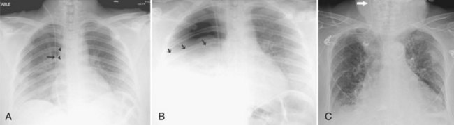
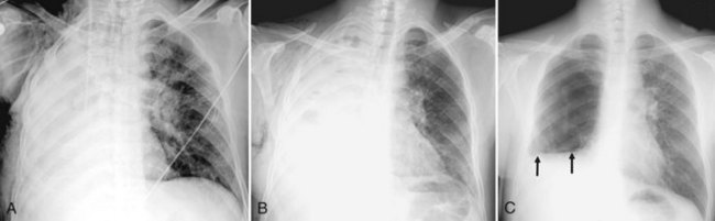
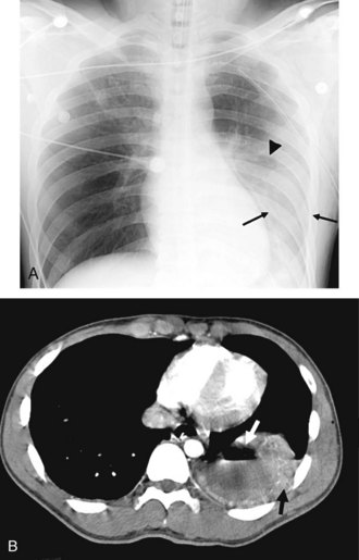
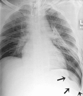
In the supine position, free gas will localize in the nondependent caudal and anteromedial aspects of the pleural space. Therefore, evidence of pneumothorax on the supine chest radiograph is often indirect and includes a low, sharp costophrenic sulcus (deep sulcus sign), relative basilar hyperlucency, increased sharpness of the ipsilateral hemidiaphragm, increased sharpness of cardiac border, presence of gas in the minor fissure, and caudal displacement of the ipsilateral hemidiaphragm (Figure 57-18). CT is more sensitive than chest radiography for detecting pneumothorax and is especially helpful in critically ill patients who cannot tolerate upright or lateral decubitus positioning. In tension pneumothorax, air enters the pleural cavity via a “ball-valve” mechanism by which it cannot escape. Chest radiographs demonstrate mediastinal shift away from the involved hemithorax, but this is infrequently captured on film owing to the clinical urgency of associated hypotension and hypoxia, mandating immediate bedside treatment.
Diaphragmatic Rupture
Rupture of the diaphragm is a rare complication in patients admitted with trauma; it is more common in penetrating trauma.46 Delay in diagnosis is common, especially in patients receiving positive-pressure ventilation, because the injury is masked by the positive-pressure gradient between the thoracic and abdominal cavities. Radiographic findings of diaphragmatic rupture include a gas-filled viscus or the tip of a properly placed enteric tube above the diaphragm, irregularity of diaphragmatic contour, elevation of the affected hemidiaphragm without atelectasis, and contralateral shift of the mediastinum without pleural effusion or pneumothorax. Diaphragmatic rupture is much more easily seen on CT, where findings include discontinuity of the diaphragm, visceral herniation, waist-like constriction of the bowel (collar sign), and layering of the herniated viscus against the posterior ribs (dependent viscera sign) (Figure 57-19).
Mediastinal Disease
Acute Traumatic Aortic Injury
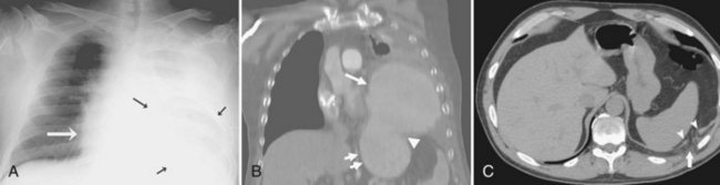
Tears of the thoracic aorta (Figure 57-20) are caused by acute deceleration injury such as occurs in a high-speed motor vehicle crash or a fall, or as a result of crush injury to the chest. A tear of the thoracic aorta almost always occurs in a transverse orientation, typically at the aortic isthmus. Tears of the ascending aorta or complete transection are nearly universally fatal, but if the adventitia remains intact, a pseudoaneurysm may form, usually with some amount of surrounding hemomediastinum. These may rupture at any time and require immediate surgical intervention.
Radiographic abnormalities that suggest aortic injury include a dense mediastinum with convex margins to the lungs, indistinct aortic contours, rightward deviation of the trachea, downward displacement of the left main bronchus, and thickening of the right paratracheal stripe Mediastinal widening is often mentioned as a sign of mediastinal hematoma, but this is an imprecise finding and not specific for aortic injury.47,48 In patients whose chest radiographs are equivocal or highly suspicious for aortic injury, contrast medium–enhanced CT is indicated. CT findings of acute aortic injury include irregularity of the aortic wall, pseudoaneurysm, abrupt change in aortic caliber, intimal flap, extravasation of contrast material, and periaortic hematoma. Evidence of hemothorax may also be seen, usually on the left, on the chest radiograph or CT.
Tracheobronchial Tree Rupture
Rupture of the tracheobronchial tree is an uncommon consequence of blunt trauma, with bronchial rupture occurring more often than rupture of the trachea.49 In bronchial rupture, the injury is usually located in the main bronchus near the carina. Disruption of the trachea typically involves the membranous portion just proximal to the carina.
Tracheobronchial disruption often causes pneumomediastinum or pneumothorax visible on chest radiographs and/or CT. The “fallen lung” sign (Figure 57-21), indicating complete bronchial disruption, describes the severed and collapsed lung lying against the posterolateral aspect of the chest wall or the diaphragm. Other findings that suggest tracheobronchial injury include a large pneumothorax not responding to percutaneous drainage, or pneumothorax and pneumomediastinum in the absence of pleural effusion. However, it should be noted that pneumomediastinum is not specific for tracheobronchial or esophageal injury after blunt trauma.50 Bronchoscopy is usually performed to confirm tracheobronchial injury, although CT with two-dimensional multiplanar reconstruction may prove a useful noninvasive alternative.51
Esophageal Rupture
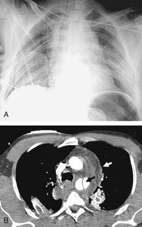
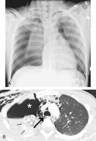
Acute rupture of the esophagus can occur by iatrogenic means, from blunt chest trauma, or in the setting of severe retching or vomiting (Boerhaave syndrome). Trauma patients are more likely to have an injury in the upper thoracic esophagus, whereas Boerhaave syndrome usually involves the lower third of the esophagus.52 Mediastinitis and septic shock rapidly follow esophageal rupture, accounting for the relatively high mortality rate. The radiographic findings of esophageal rupture include a dense mediastinum with convex margins to the lungs, pneumomediastinum, pleural effusion, pneumothorax, and hydropneumothorax. On CT, the area of greatest esophageal thickening often represents the perforation site. CT also provides more detailed information than radiography on developing complications. Contrast esophagography is the standard approach to confirm the diagnosis.
Thoracic Duct Rupture
The most common cause of thoracic duct disruption is iatrogenic injury.53 Thoracic duct injury from blunt chest injury is very rare and is thought to occur with hyperextension of the thoracic spine. Chylothorax, which usually develops several days to weeks after the trauma, is the typical radiographic finding. The delay in development of chylothorax is a clue to the diagnosis, particularly in differentiating it from traumatic hemothorax (see earlier discussion). The injury site is best identified with lymphangiography.
Vascular Disease
Pulmonary Thromboembolic Disease
Acute pulmonary embolism (PE) is a potentially lethal condition that can be difficult to diagnose clinically because of the nonspecific clinical presentation. Hospitalized patients are at increased risk of developing a PE. Although many imaging tests, including ventilation-perfusion scintigraphy and conventional pulmonary angiography, have been used to diagnose pulmonary embolism, CT pulmonary angiography (CTPA) has emerged as the initial imaging study of choice, given its high sensitivity and specificity and generally good interobserver agreement.54–57 CTPA has the additional advantage of evaluating the entire thorax for other explanations for cardiopulmonary signs and symptoms. Specifically in ICU patients, CTPA appears to be an accurate diagnostic technique; indirect CT venography (CTV) compares favorably with ultrasound in evaluating venous thrombosis and improves the diagnostic yield of CTPA alone.57–59 The addition of CTV to PE evaluation protocols is a controversial topic because it requires additional radiation and has not been conclusively demonstrated to improve patient outcomes compared to CTPA alone.59 However, this has not yet been well studied in hospitalized or critically ill patients.
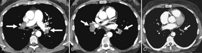
Many findings on conventional chest radiographs have been described in patients with pulmonary embolism, but they are inconsistently present and are nonspecific. Features diagnostic of acute pulmonary embolism on CTPA include a partial or complete filling defect in the pulmonary arteries (Figure 57-22). Associated lung abnormalities such as regional oligemia, volume loss, and a wedge-shaped subpleural opacity may also be present.
 Conclusion
Key Points
Hejblum G, Chalumeau-Lemoine L, Ioos V, et al. Comparison of routine and on-demand prescription of chest radiographs in mechanically ventilated adults: a multicentre, cluster-randomised, two-period crossover study. Lancet. 2009;374(9702):1687-1693.
Hill JR, Horner PE, Primack SL. ICU imaging. Clin Chest Med. 2008;29(1):59-76. vi
Rubinowitz AN, Siegel MD, Tocino I. Thoracic imaging in the ICU. Crit Care Clin. 2007;23(3):539-573.
Miller LA. Chest wall, lung, and pleural space trauma. Radiol Clin North Am. 2006;44(2):213-224. viii
Sangster GP, González-Beicos A, Carbo AI, et al. Blunt traumatic injuries of the lung parenchyma, pleura, thoracic wall, and intrathoracic airways: multidetector computer tomography imaging findings. Emerg Radiol. 2007;14(5):297-310.
Moores LK, Holley AB. Computed tomography pulmonary angiography and venography: diagnostic and prognostic properties. Semin Respir Crit Care Med. 2008;29(1):3-14.
1 Amorosa J. Appropriateness criteria: routine chest radiograph: American College of Radiology; 2006, reviewed 2008.
2 Henschke CI, Pasternack GS, Schroeder S, Hart KK, Herman PG. Bedside chest radiography: diagnostic efficacy. Radiology. 1983;149(1):23-26.
3 Bekemeyer WB, Crapo RO, Calhoon S, Cannon CY, Clayton PD. Efficacy of chest radiography in a respiratory intensive care unit. A prospective study. Chest. 1985;88:691-696.
4 Kundel HL, Seshadri SB, Langlotz CP, et al. Prospective study of a PACS: information flow and clinical action in a medical intensive care unit. Radiology. 1996;199:143-149.
5 Hejblum G, Chalumeau-Lemoine L, Ioos V, et al. Comparison of routine and on-demand prescription of chest radiographs in mechanically ventilated adults: a multicentre, cluster-randomised, two-period crossover study. Lancet. 2009;374:1687-1693.
6 Mets O, Spronk PE, Binnekade J, Stoker J, de Mol BA, Schultz MJ. Elimination of daily routine chest radiographs does not change on-demand radiography practice in post-cardiothoracic surgery patients. J Thorac Cardiovasc Surg. 2007;134:139-144.
7 Hendrikse KA, Gratama JW, Hove W, Rommes JH, Schultz MJ, Spronk PE. Low value of routine chest radiographs in a mixed medical-surgical ICU. Chest. 2007;132:823-828.
8 Krivopal M, Shlobin OA, Schwartzstein RM. Utility of daily routine portable chest radiographs in mechanically ventilated patients in the medical ICU. Chest. 2003;123:1607-1614.
9 Graat ME, Stoker J, Vroom MB, Schultz MJ. Can we abandon daily routine chest radiography in intensive care patients? J Intensive Care Med. 2005;20:238-246.
10 Clec’h C, Simon P, Hamdi A, et al. Are daily routine chest radiographs useful in critically ill, mechanically ventilated patients? A randomized study. Intensive Care Med. 2008;34:264-270.
11 McAdams HP, Samei E, Dobbins J3rd, Tourassi GD, Ravin CE. Recent advances in chest radiography. Radiology. 2006;241:663-683.
12 Kitazono MT, Lau CT, Parada AN, Renjen P, Miller WTJr. Differentiation of pleural effusions from parenchymal opacities: accuracy of bedside chest radiography. AJR Am J Roentgenol. 2010;194:407-412.
13 Gunnarsson T, Theodorsson A, Karlsson P, et al. Mobile computerized tomography scanning in the neurosurgery intensive care unit: increase in patient safety and reduction of staff workload. J Neurosurg. 2000;93:432-436.
14 Gunnarsson T, Hillman J. Clinical usefulness of bedside intracranial morphological monitoring: mobile computerized tomography in the neurosurgery intensive care unit. Report of three cases. Neurosurg Focus. 2000;9:e5.
15 Hillman J, Sturnegk P, Yonas H, et al. Bedside monitoring of CBF with xenon-CT and a mobile scanner: a novel method in neurointensive care. Br J Neurosurg. 2005;19:395-401.
16 Mayo-Smith WW, Davis LM, Clements NC, Cobb CM, Smith WJ, Tung GA. CT of the brain: a comparison of transportable and fixed-platform scanners. AJR Am J Roentgenol. 1999;173:1481-1484.
17 Teichgraber UK, Pinkernelle J, Jurgensen JS, Ricke J, Kaisers U. Portable computed tomography performed on the intensive care unit. Intensive Care Med. 2003;29:491-495.
18 Parmar HA, Lim TC, Goh JS, Tan JT, Sitoh YY, Hui F. Providing optimal radiology service in the severe acute respiratory syndrome outbreak: use of mobile CT. AJR Am J Roentgenol. 2004;182:57-60.
19 Conrardy PA, Goodman LR, Lainge F, Singer MM. Alteration of endotracheal tube position. Flexion and extension of the neck. Crit Care Med. 1976;4:7-12.
20 Zarshenas Z, Sparschu RA. Catheter placement and misplacement. Crit Care Clin. 1994;10:417-436.
21 Collins J, Stern E, editors. Chest Radiology: The Essentials. Second ed. Philadelphia: Lippincott Williams & Wilkins, 2007.
22 Greenberg SB, Murphy GS, Vender JS. Current use of the pulmonary artery catheter. Curr Opin Crit Care. 2009;15:249-253.
23 Harvey S, Young D, Brampton W, et al. Pulmonary artery catheters for adult patients in intensive care. Cochrane Database Syst Rev. 2006;3:CD003408.
24 Drover JW. Gastric versus postpyloric feeding. Gastrointest Endosc Clin N Am. 2007;17:765-775.
25 Gehlbach BK, Geppert E. The pulmonary manifestations of left heart failure. Chest. 2004;125:669-682.
26 Rubinowitz AN, Siegel MD, Tocino I. Thoracic imaging in the ICU. Crit Care Clin. 2007;23:539-573.
27 Miller RR, Ely EW. Radiographic measures of intravascular volume status: the role of vascular pedicle width. Curr Opin Crit Care. 2006;12:255-262.
28 Baumann A, Audibert G, McDonnell J, Mertes PM. Neurogenic pulmonary edema. Acta Anaesthesiol Scand. 2007;51:447-455.
29 Goss CH, Brower RG, Hudson LD, Rubenfeld GD. Incidence of acute lung injury in the United States. Crit Care Med. 2003;31:1607-1611.
30 Rubenfeld GD, Caldwell E, Peabody E, et al. Incidence and outcomes of acute lung injury. N Engl J Med. 2005;353:1685-1693.
31 Avecillas JF, Freire AX, Arroliga AC. Clinical epidemiology of acute lung injury and acute respiratory distress syndrome: incidence, diagnosis, and outcomes. Clin Chest Med. 2006;27:549-557. abstract vii
32 Bernard GR, Artigas A, Brigham KL, et al. The American-European Consensus Conference on ARDS. Definitions, mechanisms, relevant outcomes, and clinical trial coordination. Am J Respir Crit Care Med. 1994;149:818-824.
33 Muangman N, Stern EJ, Bulger EM, Jurkovich GJ, Mann FA. Chest radiographic evolution in fat embolism syndrome. J Med Assoc Thai. 2005;88:1854-1860.
34 Van den Brande FG, Hellemans S, De Schepper A, et al. Post-traumatic severe fat embolism syndrome with uncommon CT findings. Anaesth Intensive Care. 2006;34:102-106.
35 Gallardo X, Castaner E, Mata JM, Rimola J, Branera J. Nodular pattern at lung computed tomography in fat embolism syndrome: a helpful finding. J Comput Assist Tomogr. 2006;30:254-257.
36 Nucifora G, Hysko F, Vit A, Vasciaveo A. Pulmonary fat embolism: common and unusual computed tomography findings. J Comput Assist Tomogr. 2007;31:806-807.
37 Neustein SM. Reexpansion pulmonary edema. J Cardiothorac Vasc Anesth. 2007;21:887-891.
38 Feller-Kopman D, Berkowitz D, Boiselle P, Ernst A. Large-volume thoracentesis and the risk of reexpansion pulmonary edema. Ann Thorac Surg. 2007;84:1656-1661.
39 Sharma S, Maycher B, Eschun G. Radiological imaging in pneumonia: recent innovations. Curr Opin Pulm Med. 2007;13:159-169.
40 Boersma WG, Daniels JM, Lowenberg A, Boeve WJ, van de Jagt EJ. Reliability of radiographic findings and the relation to etiologic agents in community-acquired pneumonia. Respir Med. 2006;100:926-932.
41 Chae EJ, Seo JB, Kim SY, et al. Radiographic and CT findings of thoracic complications after pneumonectomy. Radiographics. 2006;26:1449-1468.
42 Peters S, Nicolas V, Heyer CM. Multidetector computed tomography-spectrum of blunt chest wall and lung injuries in polytraumatized patients. Clin Radiol. 2010;65:333-338.
43 Sangster GP, Gonzalez-Beicos A, Carbo AI, et al. Blunt traumatic injuries of the lung parenchyma, pleura, thoracic wall, and intrathoracic airways: multidetector computer tomography imaging findings. Emerg Radiol. 2007;14:297-310.
44 Miller LA. Chest wall, lung, and pleural space trauma. Radiol Clin North Am. 2006;44:213-224. viii
45 Mirvis SE. Imaging of acute thoracic injury: the advent of MDCT screening. Semin Ultrasound CT MR. 2005;26:305-331.
46 Mirvis SE, Shanmuganagthan K. Imaging hemidiaphragmatic injury. Eur Radiol. 2007;17:1411-1421.
47 Mirvis SE. Thoracic vascular injury. Radiol Clin North Am. 2006;44:181-197. vii
48 Wintermark M, Wicky S, Schnyder P. Imaging of acute traumatic injuries of the thoracic aorta. Eur Radiol. 2002;12:431-442.
49 Bertelsen S, Howitz P. Injuries of the trachea and bronchi. Thorax. 1972;27:188-194.
50 Molena D, Burr N, Zucchiatti A, et al. The incidence and clinical significance of pneumomediastinum found on computed tomography scan in blunt trauma patients. Am Surg. 2009;75:1081-1083.
51 Faure A, Floccard B, Pilleul F, et al. Multiplanar reconstruction: a new method for the diagnosis of tracheobronchial rupture? Intensive Care Med. 2007;33:2173-2178.
52 Wu JT, Mattox KL, Wall MJJr. Esophageal perforations: new perspectives and treatment paradigms. J Trauma. 2007;63:1173-1184.
53 Nair SK, Petko M, Hayward MP. Aetiology and management of chylothorax in adults. Eur J Cardiothorac Surg. 2007;32:362-369.
54 Hogg K, Brown G, Dunning J, et al. Diagnosis of pulmonary embolism with CT pulmonary angiography: a systematic review. Emerg Med J. 2006;23:172-178.
55 Quiroz R, Kucher N, Zou KH, et al. Clinical validity of a negative computed tomography scan in patients with suspected pulmonary embolism: a systematic review. JAMA. 2005;293:2012-2017.
56 Mos IC, Klok FA, Kroft LJ, DE Roos A, Dekkers OM, Huisman MV. Safety of ruling out acute pulmonary embolism by normal computed tomography pulmonary angiography in patients with an indication for computed tomography: systematic review and meta-analysis. J Thromb Haemost. 2009;7:1491-1498.
57 Stein PD, Fowler SE, Goodman LR, et al. Multidetector computed tomography for acute pulmonary embolism. N Engl J Med. 2006;354:2317-2327.
58 Ravenel JG, Northam MC, Nguyen SA. Negative predictive value of computed tomography pulmonary angiography with indirect computed tomography venography in intensive care unit patients. J Comput Assist Tomogr. 2009;33:739-742.
59 Moores LK, Holley AB. Computed tomography pulmonary angiography and venography: diagnostic and prognostic properties. Semin Respir Crit Care Med. 2008;29:3-14.
