48 Mechanical Ventilation
Positive-pressure mechanical ventilatory support provides pressure and flow to the airways to effect oxygen (O2) and carbon dioxide (CO2) transport between the environment and the pulmonary capillary bed. The goal is to maintain appropriate levels of partial pressure of O2 and CO2 in arterial blood while unloading the ventilatory muscles. Conceptually, mechanical ventilatory support can be either total or partial. With total support, the mechanical device is designed to provide virtually all the work of breathing. Although patient effort may be present and may trigger ventilator breaths or even provide a small number of spontaneous breaths, total support should provide virtually all needed minute ventilation, with minimal patient contributions. In contrast, with partial support, the mechanical device is designed to only partially unload ventilatory muscles, requiring the patient to provide the remainder of the work of breathing. In general, total support is used in acute respiratory failure when the patient’s muscles are overloaded or fatigued or when gas exchange is very unstable or unreliable. Partial support is generally used in less severe forms of respiratory failure (especially during the recovery or weaning phase). Partial support issues are discussed in Chapters 49 and 50. This chapter focuses on positive-pressure ventilation designed to provide total support.
 Device Design Features for Total Ventilatory Support
Positive-Pressure Breath Controller
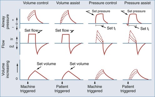
Most modern ventilators use piston-bellows systems or high-pressure gas sources to drive gas flow.1,2 Tidal breaths are generated by this gas flow and can be classified in terms of what initiates the breath (trigger variable), what controls gas delivery during the breath (target or limit variable), and what terminates the breath (cycle variable).3 During total support, breaths can be initiated (triggered) by patient effort (assisted breaths) or by the machine timer (controlled breaths). Target or limit variables are generally either a set flow or a set inspiratory pressure. With flow targeting, the ventilator adjusts pressure to maintain a clinician-determined flow pattern; with pressure targeting, the ventilator adjusts flow to maintain a clinician-determined inspiratory pressure. Cycle variables are generally a set volume or a set inspiratory time. Breaths can also be cycled if pressure limits are exceeded. The four common breath types supplied by modern mechanical ventilators to provide total support are volume control (VC), volume assist (VA), pressure control (PC), and pressure assist (PA).3 These breaths are classified by their trigger, target, and cycle features in Figure 48-1.
Mode Controller
The availability and delivery logic of different breath types define the mode of mechanical ventilatory support.3 The mode controller is an electronic, pneumatic, or microprocessor-based system designed to provide the proper combination of breaths according to set algorithms and feedback data (conditional variables). For total support, the most commonly used modes are volume assist-control and pressure assist-control. Synchronized intermittent mandatory ventilation (SIMV) can provide VA and VC or PA and PC breaths interspersed with either unsupported or partially supported spontaneous breaths (volume-targeted SIMV and pressure-targeted SIMV, respectively). When the SIMV machine breath rate is set sufficiently high, the bulk of the work required for the desired delivered minute ventilation is borne by the ventilator such that these modes can be considered to provide virtual total support. A variation on the SIMV approach is to use a pressure-targeted mode with a long inspiratory time/short expiratory time pattern and allow spontaneous breaths to occur during the long inflation phase. This approach goes by a variety of proprietary names but is most commonly referred to as airway pressure release ventilation (APRV).4 These modes are summarized according to available breath types in Table 48-1.
New ventilator designs incorporate advanced monitoring and feedback functions into these controllers to allow continuous adjustments in mode algorithms as the patient’s condition changes.5 The most common of these new feedback designs is the addition of a volume target backup to pressure assist-control, termed pressure-regulated volume control (PRVC). This feature adjusts the inspiratory pressure level above or below the clinician-set target to achieve the volume target. A more sophisticated feedback system for pressure-targeted breaths calculates a frequency–tidal volume combination that requires the least ventilator work for the desired minute ventilation. Known as adaptive support ventilation (ASV), this mode also incorporates a calculation of the expiratory time constant to assure that an expiratory time to minimize air trapping is also present.6 Finally, two new modes that are driven entirely by patient effort can be set to provide virtually all the work of breathing and thus could be considered forms of total support. One is proportional assist ventilation (PAV), which drives ventilator gas flow as a proportion of patient flow demand; the other is neurally adjusted ventilator assistance (NAVA), which drives ventilator gas flow as a proportion of the diaphragmatic electromyogram signal.6–8 These two interactive modes are discussed in more detail in Chapter 49.
Other Device Features Supporting Mechanical Ventilation
Effort sensors are pressure and/or flow transducers in the ventilator circuitry that detect patient breathing efforts and are characterized by their sensitivity and responsiveness.9 Blenders mix air and O2 to produce a delivered inspired O2 fraction (FIO2) from 0.21 to 1.0. On newer systems, blenders are also available for other gases such as heliox, nitric oxide, and anesthetic agents. Humidifiers adjust blended gas mixtures to approximate body conditions using either passive heat-moisture exchangers in the circuitry or active systems that add heat and moisture directly. Positive end-expiratory pressure (PEEP) is usually applied by regulating pressure in the expiratory valve of the ventilator system, but a continuous flow of source gas during the expiratory phase can produce a similar effect. The gas delivery circuit consists of flexible tubing that often has pressure or flow sensors and an exhalation valve. It is important to remember that this tubing has measurable compliance (generally 1–4 mL/cm H2O), and significant amounts of delivered gas may only distend this circuitry rather than enter the patient’s lungs when high airway pressures are encountered.
 Physiologic Effects of Positive-Pressure Mechanical Ventilation
Equation of Motion
Lung inflation during mechanical ventilation occurs when pressure and flow are applied at the airway opening. These applied forces interact with respiratory system compliance (both lung and chest wall components), airway resistance, and to a lesser extent, respiratory system inertance and lung tissue resistance to effect gas flow.10,11 For simplicity’s sake, because inertance and tissue resistance are relatively small, they can be ignored, and the interactions of pressure, flow, and volume with respiratory system mechanics can be expressed by the simplified equation of motion:
In a mechanically ventilated patient, this relationship is expressed as:
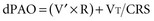
Separating chest wall and lung compliance (CCW and CL, respectively) during a passive, machine-controlled positive-pressure breath requires an esophageal pressure measurement (Pes) to approximate pleural pressure. With this measurement, the inspiratory change in Pes (dPes) can be used in the following calculations: CCW = VT/dPes, and CL = VT/(dPAO − dPes). In clinical practice, because CCW is usually quite high and dPes is thus quite low, dPAOplateau and PAOplateau are often taken as an approximation of lung distending pressure. However, in situations in which CCW is reduced (e.g., obesity, anasarca, ascites, surgical dressings), the stiff chest wall can have a significant effect on dPAOplateau and PAOplateau and must therefore be considered when using these measurements to assess lung stretch.12
Patient-Ventilator Interactions and Synchrony
During the assisted breaths of assist-control ventilation, patients interact with all three phases of breath delivery: trigger, target, and cycle.13 As noted, breath triggering occurs when patient effort is sensed by the ventilator and flow delivery is initiated. Breath triggering is characterized by sensitivity (the amount of effort required to trigger the breath) and responsiveness (the time required to have flow delivery meet the target value). Once flow delivery is initiated, ventilator flow delivery interacts with patient flow demand. Flow synchronized to demand is characterized by an airway pressure profile that is similar in shape to a controlled breath. Ventilator breath cycling that is synchronous to patient effort is characterized by a smooth transition in the airway pressure and flow graphic from inspiration to expiration.
Respiratory System Mechanics and Breath Design Features
As noted earlier, there are two basic approaches to delivering positive-pressure breaths during assist-control ventilation: pressure targeting–time cycling and flow targeting–volume cycling. Although similar ranges of tidal volume and inspiratory time are available with either strategy, these breath characteristics interact differently with changing respiratory system mechanics and patient effort.10,11 Changes in compliance or resistance cause a change in tidal volume (but not in pressure at the airway opening) with a pressure-targeted breath. In contrast, similar changes in compliance or resistance cause a change in pressure at the airway opening (but not in flow or volume) with a flow-targeted breath. Patient effort during a pressure-assist breath causes the ventilator to augment flow (and thus volume) to maintain the inspiratory pressure target; this same effort during a volume-assist breath does not affect delivered flow or volume but instead causes a fall in the measured circuit pressure. The hybrid breath design pressure-regulated volume control described earlier has basic features of pressure targeting but also has a volume feedback feature that adjusts the pressure target to maintain a clinician set volume.
Intrinsic Positive End-Expiratory Pressure and the Ventilatory Pattern
Intrinsic PEEP develops within the alveoli because of inadequate expiratory time or collapsed airways during expiration (or both). Intrinsic PEEP depends on three factors: minute ventilation, the expiratory time fraction, and the respiratory system’s expiratory time constant (the product of resistance and compliance).14 As minute ventilation increases, expiratory time fraction decreases, or time constant lengthens (i.e., higher resistance or compliance values), the potential for intrinsic PEEP to develop increases.
Distribution of Ventilation
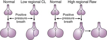
A positive-pressure tidal breath must distribute itself among the millions of alveolar units in the lung.15,16 Factors affecting this distribution include regional resistances, compliances, and functional residual capacities and the delivered flow pattern (including inspiratory pause). In general, positive-pressure breaths tend to distribute more to units with high compliance and low resistance and away from obstructed or stiff units (Figure 48-2). This creates the potential for regional overdistention of healthier lung units, even in the face of “normal-sized” tidal volumes.
 ) matching (e.g., a more uniform ventilation distribution may actually worsen (
 ) matching in a lung with inhomogeneous perfusion). Because of all these considerations, predicting which flow pattern will optimize
  matching is difficult and often an empirical trial-and-error exercise.
 Alveolar Recruitment
Infiltrative lung disease produces severe ( ) mismatching through alveolar flooding and collapse.17 In many (but not all) of these disease processes, the collapsed alveoli can be recruited during a positive-pressure ventilatory cycle.18,19 Three specific techniques to optimize recruitment are the application of PEEP, use of recruitment maneuvers, and prolongation of inspiratory time.
PEEP is defined as an elevation of transpulmonary pressures at the end of expiration.18–20 As discussed, PEEP can be produced either by expiratory circuit valves (applied PEEP) or as a consequence of ventilator settings interacting with respiratory system mechanics (intrinsic PEEP). Note that expiratory muscle contraction can also raise intrathoracic pressures at end-expiration; this should not be considered PEEP, however, because it is not a transpulmonary pressure (i.e., alveolar-pleural pressure).
Alveoli that are prevented from “derecruiting” by PEEP provide several potential benefits. First, recruited alveoli improve ( ) matching and gas exchange.18–21 Second, as discussed in more detail later, patent alveoli throughout the ventilatory cycle are not exposed to the risk of injury from the shear stress of repeated opening and closing.22 Third, PEEP prevents surfactant breakdown in collapsing alveoli and thus improves lung compliance.23
PEEP can also be detrimental. Because the tidal breath is delivered on top of the baseline PEEP, end-inspiratory pressures are raised by PEEP application.24 This must be considered if the lung is at risk for stretch injury (see Ventilator-Induced Lung Injury). Moreover, because alveolar injury is often quite heterogeneous, appropriate PEEP in one region may be suboptimal in another region and excessive in another. Optimizing PEEP is thus a balance between recruiting the recruitable alveoli in diseased regions without overdistending already recruited alveoli in healthier regions. Another potential detrimental effect of PEEP is that it raises mean intrathoracic pressure. This can compromise cardiac filling in susceptible patients (see Cardiac Effects).
Recruitment maneuvers are based on the concept that alveolar recruitment occurs throughout a positive-pressure inflation—all the way to total lung capacity.25 In practice, recruitment maneuvers are performed using sustained inflations (e.g., 30 to 40 cm H2O for up to 2 minutes).25–27 An alternative approach is to use frequent “sigh breaths” that briefly take the lung to near total capacity on a frequent basis.28 It must be pointed out that recruitment maneuvers provide only initial alveolar recruitment; the duration of recruitment almost certainly depends on an appropriate setting of PEEP to prevent subsequent derecruitment.27
Prolonging the inspiratory time (generally by adding a pause), often used in conjunction with a rapid-decelerating flow (i.e., pressure-targeted) breath, has several physiologic effects.29,30 First, the longer inflation period may lead to the opening of more slowly recruitable alveoli. Second, increased gas mixing time may improve ( ) matching in infiltrative lung disease. Third, the development of intrinsic PEEP can have similar effects to that of applied PEEP (see earlier). Indeed, much of the improvement in gas exchange associated with long inspiratory time strategies may be merely a PEEP phenomenon.30 It should be noted, however, that the distribution of intrinsic PEEP (most pronounced in lung units with long time constants) may be different from that of applied PEEP; thus, (
 ) effects may also be different.31 Fourth, because these long inspiratory times significantly increase total intrathoracic pressures, cardiac output may be affected (see Cardiac Effects). Finally, inspiratory-expiratory ratios that exceed 1 : 1 (so-called inverse ratio ventilation [IRV]) are uncomfortable, and patient sedation or paralysis is often required unless a relief mechanism allows spontaneous breathing during the inflation period (airway pressure release ventilation; see later).
 Adverse Effects of Positive-Pressure Ventilation
Ventilator-Induced Lung Injury
The lung can be injured when it is stretched excessively by positive-pressure ventilation. The most well-recognized injury is alveolar rupture, presenting as extraalveolar air in the mediastinum (pneumomediastinum), pericardium (pneumopericardium), subcutaneous tissue (subcutaneous emphysema), pleura (pneumothorax), and vasculature (air emboli).3 The risk for extraalveolar air increases as a function of the magnitude and duration of alveolar overdistention. Thus, interactions of respiratory system mechanics and mechanical ventilation strategies (high regional tidal volume and PEEP—both applied and intrinsic) that produce regions of excessive alveolar stretch (i.e., transpulmonary distending pressures in excess of 40 cm H2O) for prolonged periods create alveolar units that are at risk for rupture.
A parenchymal lung injury not associated with extraalveolar air can also be produced by mechanical ventilation strategies that stretch the lungs beyond the normal maximum (i.e., transpulmonary distending pressures > 30 to 35 cm H2O).32–35 Pathologically, this manifests as diffuse alveolar damage and is associated with cytokine release36 and bacterial translocation.37
In addition to being caused by simple overstretching of the lung, ventilator-induced lung injury (VILI) may have other determinants. Among these may be excessive tidal stretch (i.e., repetitive cycling of the lungs with tidal volumes larger than the normal 4-8 mL/kg ideal body weight)38 and a shear stress phenomenon that occurs when injured alveoli are repetitively opened and collapsed during the ventilatory cycle.22,35,39,40 VILI may also be worsened by increasing the frequency of excessive lung tidal stretch and from acceleration forces associated with rapid initial gas flow into the lung.41
VILI occurs clinically when low-resistance/high-compliance units receive a disproportionately high regional tidal volume in the setting of high alveolar distending pressures (see Figure 48-2). Concern about overdistention injury is the rationale for using “lung-protective” ventilator strategies that accept less than normal values for pH and O2 partial pressure in exchange for lower (and safer) distending pressures.
Cardiac Effects
In addition to affecting ventilation and ventilation distribution, intrathoracic pressure changes resulting from positive-pressure ventilation can affect cardiovascular function.42 In general, as mean intrathoracic pressure is increased, right ventricular filling is decreased. This is the rationale for using volume repletion to maintain cardiac output in the setting of high intrathoracic pressure. Conversely, elevations in intrathoracic pressure can actually improve left ventricular function because of an effective reduction in afterload.43 Indeed, a sudden release of intrathoracic pressure (e.g., during a ventilator disconnect or spontaneous breathing trial) can sometimes precipitate flash pulmonary edema because of the acute increase in afterload coupled with increased venous return.44
Intrathoracic pressures can influence the distribution of perfusion. The relationship of alveolar pressures to perfusion pressures in the three-zone lung model can help explain this.45 Specifically, the supine human lung is generally in a zone 3 (distention) state. As intraalveolar pressures rise, however, zone 2 and zone 1 regions can appear, creating high  units. Indeed, increases in dead space (i.e., zone 1 lung) can be a consequence of ventilatory strategies using high ventilatory pressures (e.g., IRV).
Patient-Ventilator Dyssynchrony
As mentioned, patients can interact with all three phases of an assisted breath: trigger, target, and cycle. Patients dyssynchronous with any of these phases will have unnecessary loads placed on their respiratory muscles, thereby increasing the risk of muscle fatigue. Moreover, dyssynchronous interactions produce discomfort and a sense of dyspnea. When severe, patients are often noted to be “fighting the ventilator.” This leads to unnecessary sedation and a consequent prolongation of the need for ventilatory support.46
Intrinsic Peep/Air Trapping
The development of intrinsic PEEP can produce significant adverse events. In flow- and volume-targeted ventilation, all intrathoracic pressures are increased, which can lead to risk of VILI and reduction in cardiac filling. In pressure-targeted ventilation, buildup of intrinsic PEEP results in loss of tidal volume and minute ventilation. Intrinsic PEEP can also create a significant triggering load in patients, since inspiratory muscles must first overcome intrinsic PEEP before airway and circuit pressures and flows change sufficiently to initiate the assisted breath.47
Other Adverse Effects
Oxygen concentrations approaching 100% are known to cause oxidant injury to airways and lung parenchyma.48 Many of the data supporting this concept, however, have come from animal studies, and animals and humans often have different O2 tolerances. It is unclear what the “safe” O2 concentration or duration of exposure is in sick humans. Most consensus groups have argued that FIO2 values less than 0.4 are safe for prolonged periods, and FIO2 values greater than 0.8 should be avoided if possible.
Mechanically ventilated patients are at risk for pulmonary infections for several reasons.49,50 First, the natural protective mechanism of glottic closure is compromised by an endotracheal tube. This permits continuous seepage of oropharyngeal material into the airways. Second, the endotracheal tube itself impairs the cough reflex and serves as a potential portal for pathogens to enter the lungs. This is particularly important if the circuit is contaminated. Third, airway and parenchymal injury from both the underlying disease and management complications make the lung prone to infections. Fourth, the intensive care unit (ICU) environment itself, with its heavy antibiotic use and the presence of very sick patients in close proximity, poses a risk for a variety of infections.
Preventing ventilator-associated pneumonias is critical because length of stay and mortality are heavily influenced by their development.49,50 Handwashing and carefully chosen antibiotic regimens for other infections can have important beneficial effects. Management strategies that avoid breaking the integrity of the circuit (e.g., circuit changes only when visibly contaminated) also appear to be helpful. Finally, continuous drainage of subglottic secretions may be a simple way of reducing lung contamination with oropharyngeal material.
 Applying Assist-Control Mechanical Ventilation
Tradeoffs
To provide adequate support but minimize VILI, mechanical ventilation goals must involve tradeoffs. Specifically, the need for potentially injurious pressures, volumes, and supplemental O2 must be weighed against the benefits of gas exchange support. To this end, a rethinking of gas exchange goals has occurred over the last decade; pH goals as low as 7.15 to 7.20, and O2 partial-pressure goals as low as 55 mm Hg, are now considered acceptable if the lung can be protected from VILI.51,52 Ventilator settings are thus selected to provide at least this level of gas exchange support while at the same time meeting two mechanical goals: (1) provision of enough PEEP to enlist the recruitable alveoli and (2) avoidance of a PEEP–tidal volume combination that unnecessarily overdistends lung regions at end-inspiration. These goals embody the concept of a “lung-protective” mechanical ventilatory strategy, and these principles guide current recommendations for the specific management of parenchymal and obstructive lung disease.
Managing Parenchymal Lung Injury
Parenchymal lung injury describes disease processes that involve the air spaces and interstitium of the lung. In general, parenchymal injury produces stiff lungs and reduced lung volumes.17 Functional residual capacity is thus reduced, and the compliance curve is shifted to the right. It is important to realize, however, that in all but the most diffuse diseases (e.g., diffuse cardiogenic edema), there are often marked regional differences in the degree of inflammation present and thus the degree of mechanical abnormalities that exist. This heterogeneity can have a significant impact on the effects of a particular mechanical ventilation strategy. This is because delivered gases will preferentially go to the regions with the highest compliance and lowest resistance (i.e., the more normal regions) rather than to sicker regions with low compliance (see Figure 48-2). A “normal-sized” tidal volume may thus be distributed preferentially to the healthier regions, resulting in a much higher regional tidal volume and the potential for regional overdistention injury.
Parenchymal injury can also affect the airways, especially the bronchioles and alveolar ducts.17 These narrowed and collapsible small airways can contribute to reduced regional ventilation to injured lung units. This can also lead to air trapping, and it may be a factor in subsequent cyst formation during the healing phase after lung injury.
 mismatching and shunts. Because dead space (
 = ∞) is not a major manifestation of parenchymal lung disease unless there is severe or end-stage injury, hypoxemia tends to be a greater problem than CO2 clearance.
Frequency–tidal volume settings for supporting a patient with parenchymal lung injury must focus on limiting end-inspiratory stretch. The importance of this limitation in improving outcome has been suggested by several recent clinical trials,53,54 but it was most convincingly demonstrated by the NIH ARDS Network trial, which showed a 10% absolute reduction in mortality with a ventilator strategy using a tidal volume calculated on ideal body weight of 6 mL/kg compared with 12 mL/kg.55 Because of this, initial tidal volume settings should start at 6 mL/kg ideal body weight. Moreover, strong consideration should be given to further reducing this setting if end-inspiratory plateau pressures, adjusted for any effects of excessive chest wall stiffness, exceed 30 cm H2O. Increases in tidal volume settings might be considered if there is marked patient discomfort or suboptimal gas exchange, provided the subsequent plateau pressures do not exceed 30 cm H2O. Respiratory rate settings are then adjusted to control pH. Unlike in obstructive diseases (see later), the potential for air trapping in parenchymal lung injury is low if the breathing frequency is less than 35 breaths per minute and may not develop even at frequencies exceeding 50 breaths per minute.
Setting the inspiratory time and the inspiratory-expiratory ratio in parenchymal injury involves several considerations. The normal ratio is roughly 1 : 2 to 1 : 4; such ratios produce the most comfort and are the usual initial ventilator setting. Assessment of the flow graphic should also be done to ensure that an adequate expiratory time is present to avoid air trapping. As noted earlier, inspiratory-expiratory prolongation beyond the physiologic range of 1 : 1 (IRV) can be used as an alternative to increasing PEEP to improve  matching in severe respiratory failure.29,30 A variation on IRV is airway pressure release ventilation (also known as biphasic or bilevel ventilation).4 Airway pressure release ventilation incorporates the ability to spontaneously breathe during the long inflation period of a pressure-controlled breath—a feature that may enhance recruitment and comfort.4,56
There are both mechanical and gas exchange approaches to setting the PEEP-FIO2 combination to support oxygenation. Mechanical approaches often use either a static pressure-volume plot to set the PEEP–tidal volume combination between the upper and lower inflection points57 or step increases in PEEP to determine the PEEP level that gives the best compliance.58,59 A simpler mechanical approach involves analyzing the airway pressure waveform during a set constant flow breath (the “stress index”).60 If the pressure waveform shows a steady rise, this implies that no derecruitment or overdistension is occurring during the breath. In contrast, if the pressure waveform is concave upward, it suggests overdistension is occurring; if the pressure waveform is concave downward, it implies derecruitment occurred during the previous exhalation. With any of these approaches, a recruitment maneuver could be used to recruit the maximal number of recruitable alveoli before setting the PEEP. FIO2 adjustments are then set as low as clinically acceptable.
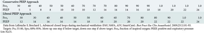
Because these mechanical approaches are time consuming and technically challenging, gas exchange criteria are often used to guide PEEP and FIO2 settings. These generally involve algorithms designed to provide adequate values for arterial partial pressure of O2 while minimizing FIO2 (see Table 48-1).61,62 Note that constructing a PEEP- FIO2 algorithm is usually an empirical exercise in balancing arterial O2 saturation with FIO2 and depends on the clinician’s perception of the relative “toxicities” of high thoracic pressures, high FIO2, and low arterial O2 saturation. Of note, however, is that recent meta-analyses of three large trials comparing conservative versus aggressive PEEP-FIO2 tables (mean PEEP of 7–9 cm H2O versus mean PEEP of 14–16 cm H2O) suggested benefit to the more aggressive strategies in patients with more severe lung injury.62
Obstructive Airway Disease
Respiratory failure from airflow obstruction is a direct consequence of increases in airway resistance. Airway narrowing and increased resistance lead to two important mechanical changes. First, the increased pressures required for airflow may overload ventilatory muscles, producing a “ventilatory pump failure,” with spontaneous minute ventilation inadequate for gas exchange. Second, the narrowed airways create regions in the lungs that cannot properly empty and return to their normal resting volume, and intrinsic PEEP is produced.14 These regions of overinflation create dead space and put inspiratory muscles at a substantial mechanical disadvantage, which further worsens muscle function. Overinflated regions may also compress healthier regions of the lung, impairing  matching. Regions of air trapping and intrinsic PEEP also function as a threshold load to trigger mechanical breaths.47,63
 mismatch, which results in progressive hypoxemia. Alveolar inflammation and flooding, however, are not characteristic features of respiratory failure due to pure airflow obstruction; thus, shunts are less of an issue than in parenchymal lung injury. Third, overdistended regions of the lungs, coupled with underlying emphysematous changes in some patients, result in capillary loss and increasing dead space. This wasted ventilation further compromises the inspiratory muscles’ ability to supply adequate ventilation for alveolar gas exchange. Emphysematous regions also have reduced recoil properties that can worsen air trapping. Fourth, hypoxemic pulmonary vasoconstriction, coupled with chronic pulmonary vascular changes in some airway diseases, overloads the right ventricle, further decreasing blood flow to the lung and making dead space worse.
Setting the frequency–tidal volume pattern in obstructive lung disease involves many considerations that are similar to those in parenchymal lung injury. Specifically, tidal volumes should be sufficiently low (e.g., 6 mL/kg ideal body weight) to ensure that plateau pressure is less than 30 cm H2O. In obstructive disease, however, clinicians should be aware that high peak airway pressures, even in the presence of acceptable values for plateau pressure, may transiently subject regions of the lung to overdistention injury due to a pendelluft effect (see Figure 48-2). As with parenchymal lung injury, tidal volume reductions should be considered to meet plateau pressure goals. Tidal volume increases can be considered for comfort or gas exchange, provided plateau pressure values do not exceed 30 cm H2O. The set rate is used to control pH. Unlike parenchymal disease, however, the elevated airway resistance and often low recoil pressures of emphysema greatly increase the potential for air trapping, and this limits the range of breath rates available.
Because alveolar recruitment is less of an issue in obstructive lung disease than in parenchymal lung injury, the PEEP-FIO2 steps in Table 48-1 should probably be shifted to emphasize FIO2 for oxygenation support. A specific role for PEEP in an obstructed patient occurs when intrinsic PEEP serves as an inspiratory threshold load on the patient’s attempting to trigger a breath. Under these conditions, judicious application of circuit PEEP (up to 75% to 85% of intrinsic PEEP) can “balance” expiratory pressure throughout the ventilator circuitry to reduce this triggering load and facilitate the triggering process.47,63
In severe airflow obstruction, use of low-density helium can facilitate ventilator settings. Helium is available as 80 : 20, 70 : 30, or 60 : 40 helium-oxygen breathing gas mixtures and can both reduce patient inspiratory work and facilitate lung emptying (recall that driving pressure decreases and flow increases through a tube as gas density decreases).64 If using a helium-oxygen gas mixture, it must be remembered that many flow sensors must be recalibrated to account for the change in gas density.
Recovering Respiratory Failure–The Ventilator Withdrawal Process
Once the cause of respiratory failure stabilizes and begins to reverse, attention turns to the ventilator withdrawal process. Numerous evidence-based guidelines have focused on the pivotal role of spontaneous breathing trials (SBTs) in determining the need for continued mechanical ventilatory support.65 In patients failing SBTs, comfortable forms of interactive ventilatory support should be provided until the next attempt at an SBT. Although the pressure-support mode is often used for this purpose, pressure assist-control can also fill this role. When using pressure assist-control, the control rate is generally set quite low (or even to zero), and the inspiratory pressure is titrated to comfort. Like pressure support, this approach is patient triggered and pressure targeted but is time cycled as opposed to the flow cycling of pressure support. Weaning and the use of partial support modes are discussed in more detail in Chapters 49 and 50.
 Conclusion
Key Points
Tremblay LN, Slutsky AS. Ventilator-induced lung injury: from the bench to the bedside. Intensive Care Med. 2006;32(1):24-33.
NIH ARDS Network. Ventilation with lower tidal volumes as compared with traditional tidal volumes for acute lung injury and the acute respiratory distress syndrome. N Engl J Med. 2000;342(18):1301-1308.
Pinsky MR, Guimond JG. The effects of positive end-expiratory pressure on heart-lung interactions. J Crit Care. 1991;6(1):1-15.
Slutsky AS. ACCP consensus conference: mechanical ventilation. Chest. 1993;104:1833-1859.
Truwit JD, Marini JJ. Evaluation of thoracic mechanics in the ventilated patient. Part I. Primary measurements. J Crit Care. 1988;3:133-150. Part II. Applied mechanics. J Crit Care. 1988;3:192-213
Briel M, Meade M, Mercat A, et al. Higher vs lower positive end-expiratory pressure in patients with acute lung injury and acute respiratory distress syndrome: systematic review and meta-analysis. JAMA. 2010;303(9):865-873.
1 Mushin M, Rendell-Baker W, Thompson PW, Mapleson WW. Automatic Ventilation of the Lungs. Oxford: Blackwell; 1980. p. 62-160
2 American Society for Testing and Materials. Standards specifications for ventilators intended for use in critical care. ASTM Standards. 1991;36:1123-1155.
3 MacIntyre NR. Principles of mechanical ventilation. Mason R, Broaddus V, editors. Murray Nadel Textbook of Respiratory Medicine, 5th edition, Philadelphia: Elsevier, 2010.
4 Habashi NM. Other approaches to open-lung ventilation: airway pressure release ventilation. Crit Care Med. 2005;33(3 Suppl):S228-S240.
5 Branson RD, MacIntyre NR. Dual control modes of mechanical ventilation. Respir Care. 1996;41:294-305.
6 Lellouche F, Brochard L. Advanced closed loops during mechanical ventilation (PAV, NAVA, ASV, SmartCare). Clinical Anaesthesiol. 2009;23:81-93.
7 Mitrouska J, Xirouchaki N, Patakas D, Siafakas N, Georgopoulos D. Effects of chemical feedback on respiratory motor and ventilatory output during different modes of assisted mechanical ventilation. Eur Respir J. 1999;13:873-882.
8 Sinderby C, Navalesi P, Beck J, et al. Neural control of mechanical ventilation in respiratory failure. Nature Med. 1999;5:1433-1436.
9 Sassoon CSH. Mechanical ventilator design and function: The trigger variable. Respir Care. 1992;37:1056-1069.
10 Truwit JD, Marini JJ. Evaluation of thoracic mechanics in the ventilated patient. Part I. Primary measurements. J Crit Care. 1988;3:133-150.
11 Truwit JD, Marini JJ. Evaluation of thoracic mechanics in the ventilated patient. Part II. Applied mechanics. J Crit Care. 1988;3:192-213.
12 Ranieri VM, Brienza N, Santostasi S, et al. Impairment of lung and chest wall mechanics in patients with acute respiratory distress syndrome: role of abdominal distension. Am J Respir Crit Care Med. 1997;156:1082-1091.
13 Prinianakis G, Kondili E, Georgopoulos D. Patient-ventilator interaction: An overview. Respir Care Clin N Am. 2005;11:201-224.
14 Marini JJ, Crooke PS. A general mathematical model for respiratory dynamics relevant to the clinical setting. Am Rev Respir Dis. 1993;147:14-24.
15 Macklen PT. Relationship between lung mechanics and ventilation distribution. Physiology. 1973;16:580-588.
16 Milic-Emili J, Henderson JAN, Dolovich MB, et al. Regional distribution of inhaled gas in the lung. J Appl Physiol. 1966;21:749-759.
17 Pratt PC. Pathology of the adult respiratory distress syndrome. In: Thurlbeck WM, Ael MR, editors. The Lung: Structure, Function and Disease. Baltimore: Williams & Wilkins; 1978:43-57.
18 Caironi P, Cressoni M, Chiumello D, et al. Lung opening and closing during ventilation of acute respiratory distress syndrome. Am J Respir Crit Care Med. 2010;181:578-586.
19 Gattinoni L, Caironi P, Cressoni M, et al. Lung recruitment in patients with the acute respiratory distress syndrome. New Engl J Med. 2006;354:1775-1786.
20 Kacmarek RM, Pierson DJ. AARC conference on positive end expiratory pressure. editors. Respir Care. 1988;33:419-527.
21 Gattinoni L, Pelosi P, Crotti S, et al. Effects of positive end expiratory pressure on regional distribution of tidal volume and recruitment in adult respiratory distress syndrome. Am J Respir Crit Care Med. 1995;151:1807-1814.
22 Webb HH, Tierney DF. Experimental pulmonary edema due to intermittent positive pressure ventilation with high inflation pressures: Protection by positive end-expiratory pressure. Am Rev Respir Dis. 1974;110:556-565.
23 Wyszogrodski I, Kyei-Aboagye K, Taaeusch HWJr, Avery ME. Surfactant inactivation by hyper ventilation: Conservation by end-expiratory pressure. J Appl Physiol. 1975;38:461-466.
24 Grasso S, Stripoli T, De Michele M, et al. ARDSNet ventilatory protocol and alveolar hyperinflation: role of positive end-expiratory pressure. Am J Resp Crit Care Med. 2007;176:761-767.
25 Crotti S, Mascheroni D, Caironi P, et al. Recruitment and derecruitment during acute respiratory failure. Am J Respir Crit Care Med. 2001;164:131-140.
26 Rimensberger PC, Prisine G, Mullen BM, et al. Lung recruitment during small tidal volume ventilation allows minimal positive end expiratory pressure without augmenting lung injury. Crit Care Med. 1999;27:1940-1945.
27 Lim SC, Adams AB, Simonson DA, et al. Intercomparison of recruitment maneuver efficacy in three models of acute lung injury. Crit Care Med. 2004;32:2371-2377.
28 Pelosi P, Cadringher P, Bottino N, et al. Sigh in acute respiratory distress syndrome. Am J Respir Crit Care Med. 1999;159:872-880.
29 Armstrong BW, MacIntyre NR. Pressure controlled inverse ratio ventilation that avoids air trapping in ARDS. Crit Care Med. 1995;23:279-285.
30 Cole AGH, Weller SF, Sykes MD. Inverse ratio ventilation compared with PEEP in adult respiratory failure. Intensive Care Med. 1984;10:227-232.
31 Kacmarek RM, Kirmse M, Nishimura M, Mang H, Kimball WR. The effects of applied vs auto-PEEP on local lung unit pressure and volume in a four-unit lung model. Chest. 1995;108:1073-1079.
32 Dreyfuss D, Saumon G. Ventilator induced lung injury: Lessons from experimental studies. Am J Respir Crit Care Med. 1998;157:294-323.
33 Dreyfuss D, Soler P, Bassett G, et al. High inflation pressure pulmonary edema. Am Rev Respir Dis. 1988;137:1159-1164.
34 Muscedere JG, Mullen JB, Gan K, Slutsky AS. Tidal ventilation at low airway pressures can augment lung injury. Am J Respir Crit Care Med. 1994;149:1327-1334.
35 Plotz FB, Slutsky AS, van Vught AJ, Heijnen CJ. Ventilator-induced lung injury and multiple system organ failure: a critical review of facts and hypotheses. Intensive Care Med. 2004;30:1865-1872.
36 Ranieri VM, Suter PM, Totorella C, et al. Effect of mechanical ventilation on inflammatory mediators in patients with acute respiratory distress syndrome. JAMA. 1999;282:54-61.
37 Nahum A, Hoyt J, Schmitz L, et al. Effect of mechanical ventilation strategy on dissemination of intertracheally instilled E. coli in dogs. Crit Care Med. 1997;25:1733-1743.
38 Hager DN, Krishnan JA, Hayden DL, Brower RG. Tidal volume reduction in patients with acute lung injury when plateau pressures are not high. Am J Respir Crit Care Med. 2005;172:1241-1245.
39 Benito S, Lemaire F. Pulmonary pressure-volume relationship in acute respiratory distress syndrome in adults: Role of positive and expiratory pressure. J Crit Care. 1990;5:27-34.
40 Gajic O, Lee J, Doerr CH, et al. Ventilator-induced cell wounding and repair in the intact lung. Am J Respir Crit Care Med. 2003;167:1057-1063.
41 Rich BR, Reickert CA, Sawada S, et al. Effect of rate and inspiratory flow on ventilator induced lung injury. J Trauma. 2000;49:903-911.
42 Pinsky MR, Guimond JG. The effects of positive end-expiratory pressure on heart-lung interactions. J Crit Care. 1991;6:1-15.
43 Marini JJ, Culver BH, Butler J. Mechanical effect of lung inflation with positive pressure on cardiac function. Am Rev Respir Dis. 1979;124:382-386.
44 Lemaire F, Teboul JL, Cinotti L, et al. Acute left ventricular dysfunction during unsuccessful weaning from mechanical ventilation. Anesthesiology. 1988;69:171-179.
45 Hughes JM, Glazier JB, Maloney JE, West JB. Effect of lung volume on the distribution of pulmonary blood flow in man. Respir Physiol. 1968;4:58-72.
46 Thille AW, Rodriguez P, Cabello B, Lellouche F, Brochard L. Patient-ventilator asynchrony during assisted mechanical ventilation. Int Care Med. 2006;32:1515-1522.
47 MacIntyre NR, McConnell R, Cheng KC. Applied PEEP reduces the inspiratory load of intrinsic PEEP during pressure support. Chest. 1997;1111:188-193.
48 Jenkinson SG. Oxygen toxicity. New Horiz. 1993;1:504-511.
49 Fagon J, Chastre J, Domart Y, et al. Nosocomial pneumonia in patients receiving continuous mechanical ventilation. Am Rev Respir Dis. 1989;139:877-884.
50 Collard HR, Saint S, Matthay MA. Prevention of ventilator-associated pneumonia: an evidence-based systematic review. Ann Intern Med. 2003;138:494-501.
51 Hager DN, Brower RG. Customizing lung-protective mechanical ventilation strategies. Crit Care Med. 2006;34:1554-1555.
52 Slutsky AS. ACCP consensus conference: Mechanical ventilation. Chest. 1993;104:1833-1859.
53 Amato MB, Barbas CSV, Medievos DM, et al. Effect of a protective ventilation strategy on mortality in ARDS. N Engl J Med. 1998;338:347-354.
54 Villar J, Kacmarek R, Peres-Mendez L, et al. A high positive end expiratory pressure low tidal volume strategy improves outcome in persistent ARDS. Crit Care Med. 2006;34:1311-1318.
55 NIH ARDS Network. Ventilation with lower tidal volumes as compared with traditional tidal volumes for acute lung injury and the acute respiratory distress syndrome. N Engl J Med. 2000;342:1301-1308.
56 Myers T, MacIntyre NR. Does airway pressure release ventilation offer important new advantages in mechanical ventilatory support? Resp Care. 2007;52:452-460.
57 Putensen C, Bain M, Hormann C. Selecting ventilator settings according to the variables derived from the quasi static pressure volume relationship in patients with acute lung injury. Anesth Analg. 1993;77:436-447.
58 Suter PM, Fairley HB, Isenberg MD. Optimal end expiratory pressure in patients with acute pulmonary failure. N Engl J Med. 1975;292:284-289.
59 Caramez MP, Kacmarek RM, Helmy M, et al. A comparison of methods to identify open-lung PEEP. Intensive Care Med. 2009;35:740-747.
60 Grasso S, Terragni P, Mascia L, et al. Ranieri VM. Airway pressure-time curve profile (stress index) detects tidal recruitment/hyperinflation in experimental acute lung injury. Crit Care Med. 2004;32:1018-1027.
61 Phoenix SI, Paravastu S, Columb M, Vincent JL, Nirmalan M. Does a higher positive end expiratory pressure decrease mortality in acute respiratory distress syndrome? A systematic review and meta-analysis. Anesthesiology. 2009;110:1098-2005.
62 Briel M, Meade M, Mercat A, et al. Higher vs lower positive end-expiratory pressure in patients with acute lung injury and acute respiratory distress syndrome: systematic review and meta-analysis. JAMA. 2010;303:865-873.
63 Reissmann HK, Ranieri VM, Goldberg P, Gottfried SB. Continuous positive airway pressure facilitates spontaneous breathing in weaning chronic obstructive pulmonary disease patients by improving breathing pattern and gas exchange. Intensive Care Med. 2000;26:1764-1772.
64 McConnell RR. Adjuncts to mechanical ventilation. In: MacIntyre NR, Branson RD, editors. Mechanical Ventilation. Philadelphia: WB Saunders; 2001:400-414.
65 ACCP/AARC/SCCM Task Force. Evidence based guidelines for weaning and discontinuing mechanical ventilatory support. Chest 2001; 120: suppl 6. Also in Resp Care. 2002;47:20-35.
